italiano impianto green lift fluitronic ... - local gmv · apparecchiature fluidodinamiche e...
TRANSCRIPT

APPARECCHIATURE FLUIDODINAMICHE E COMPONENTI PER ASCENSORI
Azienda Certificata UNI EN ISO 9001
GMV SpA Via Don Gnocchi, 10 - 20016 PERO – Milano (Italy) TEL. +39 02 33930.1 - FAX +39 02 3390379 - http://www.gmv.it - e-mail: [email protected]
EN Doc. n° - 23.07.2009 File: NGV-MI-02-10991447EN-11405P.doc
Italiano IMPIANTO GREEN LIFT FLUITRONIC
EN INSTALLATION MANUAL
NGV VALVE
AVAILABLE WITH
TANK TYPE
q GL q F1 q T2 q MRL-T q MRL-H
COD. 1 0991 447/B

INDEX
COD 1 0991 447 -Index-
INDEX 1 HYDRAULIC CIRCUIT ..................................................................................................... 1
2 OVERPRESSURE VALVE (VS) ADJUSTMENT.............................................................. 2
3 RAM PRESSURE ON THE VSMA ADJUSTMENT (2:1 INSTALLATIONS) ..................... 3
4 PIPE RUPTURE VALVE (VC) TEST................................................................................ 4
5 DECELERATION DISTANCES ........................................................................................ 5
6 ELECTRICAL PART......................................................................................................... 6 6.1 NGV01 control board features ................................................................................... 6 6.2 Wiring specifics .......................................................................................................... 7
6.2.1 Controller interface .............................................................................................. 7 6.2.2 Valve interface .................................................................................................... 8
6.3 Controller wiring schemas.......................................................................................... 9 6.3.1 Optimal configuration ........................................................................................ 10
6.3.1.1 Schema 1.................................................................................................... 10 6.3.1.2 Schema 2.................................................................................................... 11
6.3.2 Adapting of existing controllers ......................................................................... 12 6.3.2.1 Schema 1 – Modernization with supply up to 60Vdc .................................. 12 6.3.2.2 Schema 2 – Modernization with supply grater than 60V............................. 13
6.4 Signals sequence and timing ................................................................................... 14 6.4.1 Upward.............................................................................................................. 14 6.4.2 Downward ......................................................................................................... 15
7 PROGRAMMING ........................................................................................................... 17
8 OUTPUT PROGRAMMABLE FUNCTIONS CHART...................................................... 28
9 FAILURE CHART........................................................................................................... 29

HYDRAULIC CIRCUIT
COD 10991 447 - 1 -
1 HYDRAULIC CIRCUIT
K Check valve ML Manual lowering button
ISP Inspection gauge fitting VS Overpressure valve MAN Manometer VSMA Manual lowering valve
PT Pressure transducer VC Pipe rupture valve VB Flow control valve SM Stepping motor
VMD Down solenoid valve VRP Pilot operated check valve VR1 Check valve (inlet) VS1 Overpressure valve (hand pump) VR2 Check valve (outlet) VR Check valve
PAM Hand pump TT Temperature transducer 1 VS valve adjustment 4 Manometer shut-off valve 2 VS1 valve adjustment (hand pump) 5 Shut-off valve for rupture valve test 3 Ram pressure adjustment (only for indirect acting jacks 2:1)
OVERPRESSURE VALVE (VS) ADJUSTMENT
COD 10991 447 - 2 -
2 OVERPRESSURE VALVE (VS) ADJUSTMENT
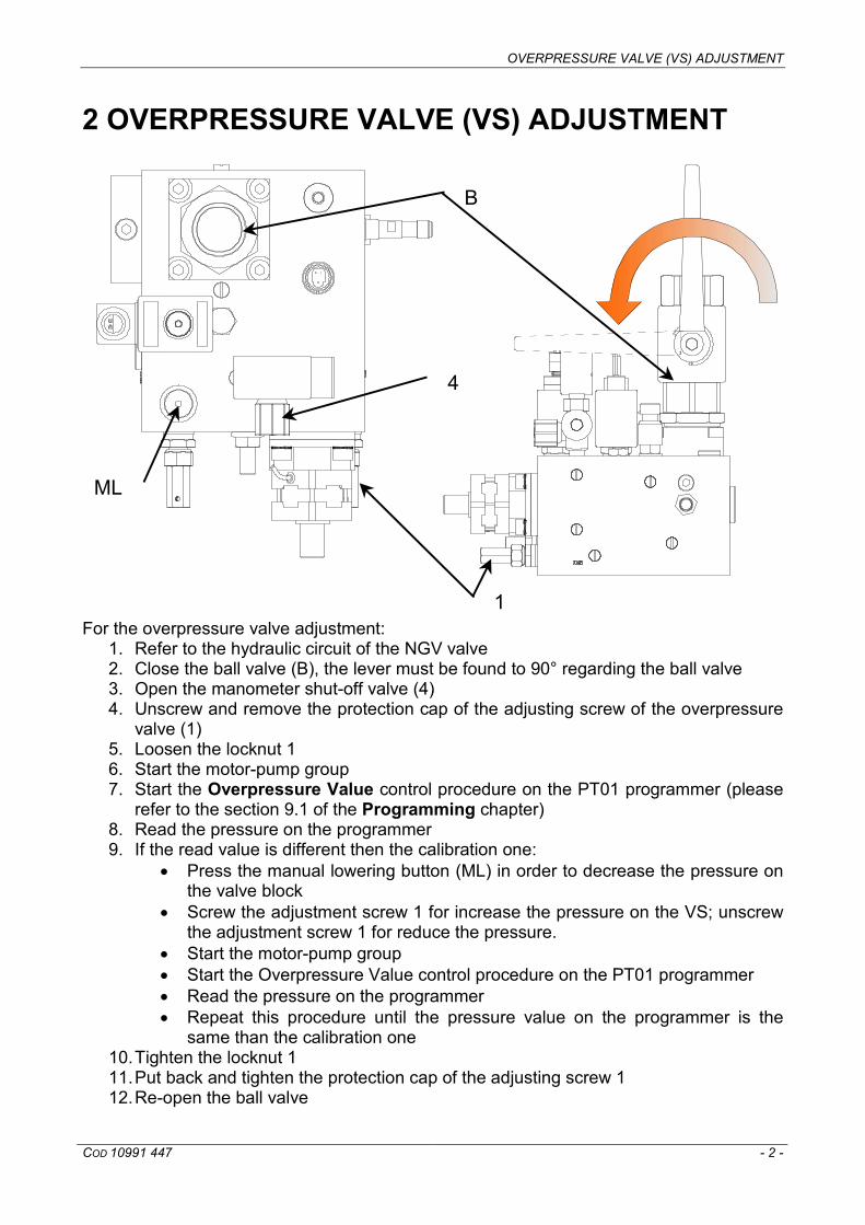
For the overpressure valve adjustment:
1. Refer to the hydraulic circuit of the NGV valve 2. Close the ball valve (B), the lever must be found to 90° regarding the ball valve 3. Open the manometer shut-off valve (4) 4. Unscrew and remove the protection cap of the adjusting screw of the overpressure
valve (1) 5. Loosen the locknut 1 6. Start the motor-pump group 7. Start the Overpressure Value control procedure on the PT01 programmer (please
refer to the section 9.1 of the Programming chapter) 8. Read the pressure on the programmer 9. If the read value is different then the calibration one:
• Press the manual lowering button (ML) in order to decrease the pressure on the valve block
• Screw the adjustment screw 1 for increase the pressure on the VS; unscrew the adjustment screw 1 for reduce the pressure.
• Start the motor-pump group • Start the Overpressure Value control procedure on the PT01 programmer • Read the pressure on the programmer • Repeat this procedure until the pressure value on the programmer is the
same than the calibration one 10. Tighten the locknut 1 11. Put back and tighten the protection cap of the adjusting screw 1 12. Re-open the ball valve
4
B
ML
1

DECELERATION DISTANCES
COD 10991 447 - 3 -
3 RAM PRESSURE ON THE VSMA ADJUSTMENT (2:1 INSTALLATIONS)
For the ram pressure on the VSMA adjustment:
1. Close the ball valve (B), the lever must be found to 90° regarding the ball valve 2. Unscrew and remove the protection cap of the adjusting screw of the VSMA valve
(3) 3. Press the manual lowering button (ML) 4. Check the pressure gauge on the manometer (MAN) is around 5 bar. If it is 5 bar go
to point 6, if it is less then 5 bar go to point 5 5.
a) Re-open the ball valve B b) Loosen the locknut 3 c) Tighten the screw 3 – one turn d) Tighten the locknut 3 e) Close the ball valve B f) Press the manual lowering button ML g) Repeat this procedure until the pressure is close to 5 bar h) Go to point 6
6. Put back and tighten the protection cap of the adjusting screw 3 7. Re-open the ball valve B
4
MAN
B
3
ML

PIPE RUPTURE VALVE (VC) TEST
COD 10991 447 - 4 -
4 PIPE RUPTURE VALVE (VC) TEST
CAUTION! GENERAL DANDER: Before testing the pipe rupture valve, adjust this valve on the cylinder (refer to the technical data on the plant) To test the pipe rupture valve follow the next procedure:
1. Move the elevator to the highest floor at full load (refer to plant operation manual) 2. After the car comes to a full stop loosen the locknut 5 and unscrew the screw 5 – 3
turns 3. Start the Pipe Rupture test procedure on the PT01 programmer (please refer to the
section 9.2 of the Programming chapter) 4. At the end of the test fully tighten the screw 5 and tighten the locknut 5
5

DECELERATION DISTANCES
COD 10991 447 - 5 -
5 DECELERATION DISTANCES
VN [m/s] DRAL, D [m] 0,20 0,18 0,25 0,24 0,30 0,29 0,35 0,36 0,40 0,43 0,45 0,50 0,50 0,58 0,55 0,66 0,60 0,76 0,65 0,85 0,70 0,95 0,75 1,06 0,80 1,17 0,85 1,29 0,90 1,42 0,95 1,54 1,00 1,68
VN [m/s] DRAL,S [m] 0,20 0,18 0,25 0,24 0,30 0,29 0,35 0,36 0,40 0,43 0,45 0,50 0,50 0,58 0,55 0,66 0,60 0,76 0,65 0,85 0,70 0,95 0,75 1,06 0,80 1,17 0,85 1,29 0,90 1,42 0,95 1,54 1,00 1,68
The distance between the deceleration sensor and the floor must be regulated according to the chart above. If the levelling space is greater is possible to make an adjustment using the programmer as shown in the chapter Programming.

ELECTRICAL PART
COD 10991 447 - 6 -
6 ELECTRICAL PART
6.1 NGV01 control board features
The hardware features of the NGV01 control board are:
• Supply: 40Vdc not stabilized, obtained from a 30Vac ±15% source rectified. For different supplies refer to the wiring schemas section
• Signals from controller interface: o 24...50Vdc isolated, Upward signal (VS), Nominal speed signal (V0),
Intermediate speed signal (V1), Inspection speed signal (V2). For grater voltages refer to the wirings with existing controllers section
o 24...100Vdc, 110...180Vdc selected by a jumper (J2) for Downward signal/command (VMD)
• N° 4 output relè without voltage and programmable for monitoring and fault check (refer to the Output Programmable Functions Chart)
• Pressure transducer interface 4...20mA, supply 12Vdc • PTC temperature transducer interface (1000Ω 25°C) • Inductive sensor for VRP position check (IND) interface, supply 12Vdc, signal
12Vdc max • Stepping motor driver: 52Vdc max @2A RMS • VMD command, in series with D signal, max. 2A, EN81.2 surface isolation
distances and in air compliant • RS232 interface by RJ45 connector, suitable both for PT01 programmer and for PC
connection
ELECTRICAL PART
COD 10991 447 - 7 -
• N°2 diagnostic led: o supply state, GREEN led:
§ SWITCHED OFF: no supply voltage § BLINKING: supply voltage out of the ranges § ON (FIXED): correct supply voltage
o alarm state, RED led: § SWITCHED OFF: no alarm § BLINKING: alarm that blocks the lift § ON (FIXED): alarm that doesn’t block the lift
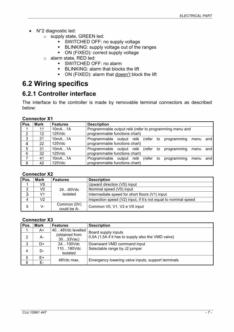
6.2 Wiring specifics 6.2.1 Controller interface The interface to the controller is made by removable terminal connectors as described below: Connector X1 Pos. Mark Features Description
1 11 2 12
10mA…1A 125Vdc
Programmable output relè (refer to programming menu and programmable functions chart)
3 21 4 22
10mA…1A 125Vdc
Programmable output relè (refer to programming menu and programmable functions chart)
5 31 6 32
10mA…1A 125Vdc
Programmable output relè (refer to programming menu and programmable functions chart)
7 41 8 42
10mA…1A 125Vdc
Programmable output relè (refer to programming menu and programmable functions chart)
Connector X2 Pos. Mark Features Description
1 VS Upward direction (VS) input 2 V0 Nominal speed (V0) input 3 V1 Intermediate speed for short floors (V1) input 4 V2
24…60Vdc isolated
Inspection speed (V2) input, if it’s not equal to nominal speed
5 V- Common (0V) could be A- Common V0, V1, V2 e VS input
Connector X3 Pos. Mark Features Description
1 A+
2 A-
40…48Vdc levelled (obtained from
30…33Vac)
Board supply inputs 0,5A (1,5A if it has to supply also the VMD valve)
3 D+
4 D-
24…100Vdc 110…180Vdc
isolated
Downward VMD command input Selectable range by J2 jumper
5 E+ 6 E- 48Vdc max. Emergency lowering valve inputs, support terminals

ELECTRICAL PART
COD 10991 447 - 8 -
The input circuits are divided into two groups, both isolated from the board supply: • V0,V1,V2,VS in common with V- • D+ in common with D-
Jumper J2
Pos. Description
VMD downward input and command 24…100Vdc
VMD downward input and command 110…180Vdc
6.2.2 Valve interface The interface to the valve is described below: Connector X4 Pos. Mark Description
1 E- 2 E+ Emergency lowering valve outputs
3 D- 4 VMD VMD downward command outputs
Connector X5 Stepping motor connector made by a pre-assembled AMP terminal Connector X6 Pos. Mark Features Description
1 TS1 +Ref 2 TS2 2KΩ max.
Temperature transducer inputs
3 TP1 +12Vdc 4 TP2 4…20mA return Pressure transducer inputs
Connettore X7 Pos. Mark Features Description
1 TP4 +12Vdc Inductive sensor power supply 2 TP5 0…12Vdc Inductive sensor input signal (IND) 3 TP6 0V Inductive sensor common
ELECTRICAL PART
COD 10991 447 - 9 -
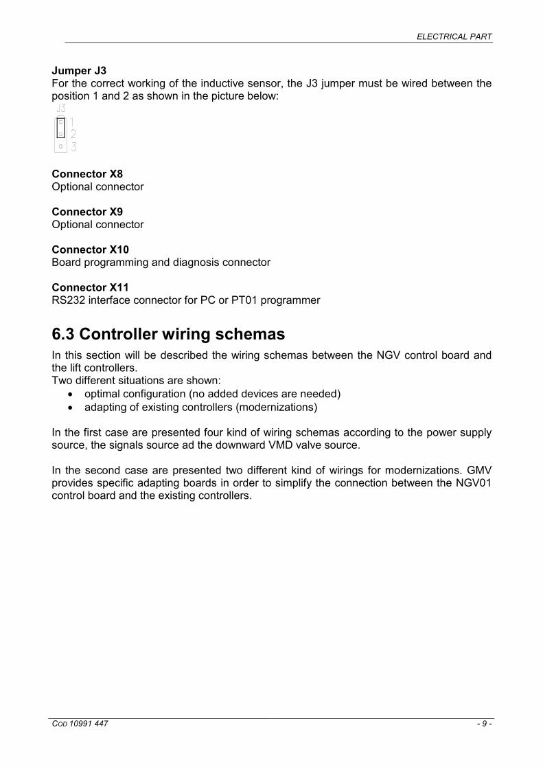
Jumper J3 For the correct working of the inductive sensor, the J3 jumper must be wired between the position 1 and 2 as shown in the picture below:
Connector X8 Optional connector Connector X9 Optional connector Connector X10 Board programming and diagnosis connector Connector X11 RS232 interface connector for PC or PT01 programmer
6.3 Controller wiring schemas In this section will be described the wiring schemas between the NGV control board and the lift controllers. Two different situations are shown:
• optimal configuration (no added devices are needed) • adapting of existing controllers (modernizations)
In the first case are presented four kind of wiring schemas according to the power supply source, the signals source ad the downward VMD valve source. In the second case are presented two different kind of wirings for modernizations. GMV provides specific adapting boards in order to simplify the connection between the NGV01 control board and the existing controllers.

ELECTRICAL PART
COD 10991 447 - 10 -
6.3.1 Optimal configuration 6.3.1.1 Schema 1 Features:
• VMD voltage independent from the board supply voltage • Signals voltage in common with the board supply voltage

ELECTRICAL PART
COD 10991 447 - 11 -
6.3.1.2 Schema 2 Features:
• Independent board supply voltage • Independent signals voltage (PLC, custom board, etc.) • Independent VMD voltage

ELECTRICAL PART
COD 10991 447 - 12 -
6.3.2 Adapting of existing controllers 6.3.2.1 Schema 1 – Modernization with supply up to 60Vdc

ELECTRICAL PART
COD 10991 447 - 13 -
6.3.2.2 Schema 2 – Modernization with supply grater than 60V

ELECTRICAL PART
COD 10991 447 - 14 -
6.4 Signals sequence and timing NGV01 input signals sequence and timing both for upward and for downward lift runs are shown below:
6.4.1 Upward
Time T* depends on motor starting. VS signal must be switched ON when the motor is completely started. The chart below shows the meaning of the various combinations of the input signals: VS V0 V1 V2 1 1 0 0 High Speed 1 X 1 0 Intermediate Speed 1 X X 1 Inspection Speed 1 0 0 0 Levelling/Re-levelling Speed Where: 1 Energized 0 Not Energized X Anything N.B. It is necessary to have 2,5 ” sec. delay before changing direction of travel.

ELECTRICAL PART
COD 10991 447 - 15 -
6.4.2 Downward
The chart below shows the meaning of the various combinations of the input signals: D V0 V1 V2 1 1 0 0 High Speed 1 X 1 0 Intermediate Speed 1 X X 1 Inspection Speed 1 0 0 0 Levelling/Re-levelling Speed Where: 1 Energized 0 Not Energized X Anything N.B. It is necessary to have 2,5 ” sec. delay before changing direction of travel.

ELECTRICAL PART
COD 10991 447 - 16 -

PROGRAMMING
COD 10991 447 - 17 -
7 PROGRAMMING
It is possible to dialog with the NGV01 control board by the programmer PT01. The connection between the programmer and the board is made by a network UTP RJ45 straight cable. The programmer power supply comes from the control board through the connection cable. It is possible to navigate into the menus and change the numeric values using the arrow keys Ý Þ, it is possible to enter into the sub-menus and confirm the input data by the ENT key and finally it’s possible exit and move the cursor left side by the ESC key.
Network UTP RJ45 straight cable
PT01

PROGRAMMING
COD 10991 447 - 18 -
DIAGNOSTICS NGV VER XX.XXX 1 DIAGNOSTICS
Ý Þ 1.1 PRESSURE XX.X bar Pressure gauge [bar] read by the pressure transducer
Ý Þ 1.2 TEMPERATURE XX.X °C Temperature gauge [°C] read by the temperature
transducer Ý Þ 1.3 REF. SPEED X.XXX m/s Set point speed [m/s]
Ý Þ State of the input signals 1.4 INPUT S012DI
000000 S012DI S012DI
100000=VS 010000=V0 001000=V1
000010=D 000100=V2 000001=IND
Ý Þ State of the output signals 1.5 OUTPUT 1234D
00000 1234D 1234D
10000=OUTPUT #1 01000=OUTPUT #2 00100=OUTPUT #3
00010=OUTPUT #4 00001=VMD
Ý Þ 1.6 SUPPLY XX.X V Supply voltage [V] of the control board
Ý Þ 1.7 FLY TIME Fly time of the lift
ENT 1.7.1 TOTAL XXX.X s Total time of the lift trip [s]
Ý Þ 1.7.2 START->DEC XXX.X s Time between the start of the lift end the start of the
deceleration phase [s] Ý Þ

PROGRAMMING
COD 10991 447 - 19 -
Ý Þ 1.7.3 DEC->STOP XXX.X s Time between the start of the deceleration phase and the
stop of the lift [s]
ALARM NGV VER XX.XXX 2-ALARM
Ý Þ 2.1 ALARM 00:No Alarm
Active alarms. Each alarm is identified by a code explained in the Failure Chart. Last 8 alarms are stored in memory
ALARM AND FAULT RESET NGV VER XX.XXX 3-AL/FLT RESET
Ý Þ 3.1 FAULT RESET Pressing the ENT key on the programmer all the faults and
the alarms are deleted

PROGRAMMING
COD 10991 447 - 20 -
ADJUSTMENTS NGV VER XX.XXX 4-ADJUSTMENTS
+Ý -Þ 4.1 START UP MIN ±XX.X
UPWARD start adjustment (-99 ÷ +99)
ÝÞ
+Ý -Þ 4.2 SLOW. UP MIN ±XX.X
UPWARD levelling speed adjustment (-99 ÷ +99)
Ý
Þ
+Ý -Þ 4.3 HIGH DN MIN ±XX.X
DOWNWARD high speed adjustment (-99 ÷ +99)
Ý
Þ
+Ý -Þ 4.4 SLOW. DN MIN ±XX.X
DOWNWARD levelling speed adjustment (-99 ÷ +99)
Ý
Þ

PROGRAMMING
COD 10991 447 - 21 -
+Ý -Þ 4.5 START. UP MAX ±XX.X
UPWARD start adjustment (-99 ÷ +99)
ÝÞ
+Ý -Þ 4.6 SLOW. UP MAX ±XX.X
UPWARD levelling speed adjustment (-99 ÷ +99)
Ý
Þ
+Ý -Þ 4.7 HIGH DN MAX ±XX.X mm
DOWNWARD high speed adjustment (-99 ÷ +99)
Ý
Þ
+Ý -Þ 4.8 SLOW DN MAX ±XX.X mm
DOWNWARD levelling speed adjustment (-99 ÷ +99)
Ý
Þ

PROGRAMMING
COD 10991 447 - 22 -
Ý Þ 4.9 OFFSET V0 UP XXX mm
UPWARD levelling space adjustment in NOMINAL speed (0 ÷ 600 mm)
Ý Þ 4.10 OFFSET V0 DN XXX mm
DOWNWARD levelling space adjustment in NOMINAL speed (0 ÷ 600 mm)
Ý Þ 4.11 OFFSET V1 UP XXX mm
UPWARD levelling space adjustment in INTERMEDIATE speed (0 ÷ 600 mm)
Ý Þ 4.12 OFFSET V1 DN XXX mm
DOWNWARD levelling space adjustment in INTERMEDIATE speed (0 ÷ 600 mm)

PROGRAMMING
COD 10991 447 - 23 -
SETTINGS Data inserted by GMV robe checked during the installation of the unit. NGV VER XX.XXX 5-SETTINGS
Ý Þ 5.1 LIFT RATIO X:X Ratio of the lift system (1:1; 2:1; 3:1)
Ý Þ 5.2 JACK DIAM. XXX mm Equivalent piston diameter (SEE TABLE). [mm]
Ý Þ 5.3 PUMP FLOW XXX l/min Flow rate of the pump [l/min]
Ý Þ 5.4 MAP XXXX Map code of the power unit
Ý Þ 5.5 PSTAT MIN. XX.X bar Minimum static pressure (5.0 ÷ 45.0 bar)
Ý Þ 5.6 Pstat Max. XX.X bar Maximum static pressure
(Pstat Min. ÷ 45.0 bar) Ý Þ 5.7 P MIN. XX.X bar Minimum pressure (1.0 ÷ 10.0 bar)
Ý Þ 5.8 P FULL LOAD XX.X bar Full load pressure, 80% of nominal load (12.0 ÷ 45.0 bar)*
Ý Þ 5.9 P OVERLOAD XX.X bar Overload pressure, 110% of nominal load (12.0 ÷ 45.0
bar)* Ý Þ 5.10 P MAX XX.X bar Maximum pressure, 140% of nominal load (15.0 ÷ 70.0
bar)* * Re-calculated value when the Pstat,MIN value (parameter 5.5) or the Pstat,MAX value (parameter 5.6) are modified
Ý Þ 5.11 COOL TEMP. XX °C Maximum fluid temperature
(5.0 ÷ 70.0 °C)

PROGRAMMING
COD 10991 447 - 24 -
UPWARD PARAMETERS NGV VER XX.XXX 6-UP PARAMETERS
Ý Þ 6.1 NOM.SPEED V0 X.XX m/s Nominal speed [m/s] referred to the nominal pump flow,
piston diameter and size, value not modifiable. Ý Þ 6.2 INT.SPEED V1 X.XX m/s Intermediate speed [m/s]
(15 ÷ 75 % x Nominal Speed) Ý Þ 6.3 INS.SPEED V2 X.XX m/s Inspection speed (0.15 ÷ 0.63 m/s)

PROGRAMMING
COD 10991 447 - 25 -
DOWNWARD PARAMETERS NGV VER XX.XXX 7-DN PARAMETERS
Ý Þ 7.1 NOM.SPEED V0 X.XX m/s Enter required nominal downward speed (m/s…) . es: 0,63
Ý Þ 7.2 INT.SPEED V1 X.XX m/s Indicates the Intermediate speed [m/s]
(15 ÷ 75 % x Nominal Speed) Ý Þ 7.3 RELEV. SPEED X.XXX m/s Re-levelling speed (0.010 ÷ 0.150 m/s))

PROGRAMMING
COD 10991 447 - 26 -
OUTPUT FUNCTIONS NGV VER XX.XXX 8-OUTPUT FUNC.
Ý Þ 8.1 OUTPUT 11-12 FUNXXXX
Active function on output 11-12. Every function is identified by a code described into Output Programmable Functions Chart
Ý Þ 8.2 OUTPUT 21-22 FUNXXXX
Active function on output 21-22. Every function is identified by a code described into Output Programmable Functions Chart
Ý Þ 8.3 OUTPUT 31-32 FUNXXXX
Active function on output 31-32. Every function is identified by a code described into Output Programmable Functions Chart
Ý Þ 8.4 OUTPUT 41-42 FUNXXXX
Active function on output 41-42. Every function is identified by a code described into Output Programmable Functions Chart
As default the output are set up with this functions:
• Output 11-12: Maximum pressure or minimum pressure (03NC) • Output 21-22: Overload (08NO) • Output 31-32: Maximum temperature oil (05NC) • Output 41-42: Fault (09NO)

PROGRAMMING
COD 10991 447 - 27 -
CALIBRATION NGV VER XX.XXX 9-CALIBRATION
Ý Þ 9.1 OVERP. VALUE ENT=Start
Starts the routine for the control of the adjusted pressure on the overpressure valve. For the overpressure value test please refer to the Overpressure Valve (VS) Adjustment chapter. This routine needs VS and V0 input signals for working. Press ENT to start the routine. The display blinks while the routine is working, at the end of the routine the fixed value is the adjustment value of the overpressure valve. Press ESC to exit and ENT to start again.
Ý Þ 9.2 PIPE RUPTURE ENT=Start
Starts the routine for the test of the pipe rupture valve. For the pipe rupture valve test please refer to the Pipe Rupture (VC) Test chapter. This routine needs D and V0 input signals for working. Press ENT to start the routine. The routine is ended when the D signal falls down. Press ESC to exit and ENT to start again.
ADVANCED PROGRAMMING NGV VER XX.XXX 10-ADVANCED
Ý Þ 10.1 PASSWORD 00000
Entering the password it’s possible to read and modify the entire parameters of the NGV valve

OUTPUT PROGRAMMABLE FUNCTIONS CHART
COD 10991 447 - 28 -
8 OUTPUT PROGRAMMABLE FUNCTIONS CHART The outputs 11-12; 21-22; 31-32; 41-42 are programmable with a specific function. Each function could be used as NO or as NC. The available functions are: Function Description PT01 Code
0 No function, output OFF FUN00
1 Minimum pressure (see parameter 5.7 into the Programming section)
FUN01NC FUN01NO
2 Maximum pressure (see parameter 5.10 into the Programming section)
FUN02NC FUN02NO
3 Maximum pressure or minimum pressure FUN03NC FUN03NO
4 Minimum temperature (<5°C) FUN04NC FUN04NO
5 Maximum temperature (see parameter 5.11 into the Programming section)
FUN05NC FUN05NO
6 Maximum temperature or minimum temperature FUN06NC FUN06NO
7 Full load (see parameter 5.8 into the Programming section)
FUN07NC FUN07NO
8 Overload (see parameter 5.9 into the Programming section)
FUN08NC FUN08NO
9 Fault: High/Low supply; DriverSM; VRP Check; contemporaneous Upward and Downward commands
FUN09NC FUN09NO
10 Fault or minimum pressure FUN010NC FUN010NO
11 Fault or maximum pressure FUN011NC FUN011NO
12 Fault or minimum pressure or maximum pressure FUN012NC FUN012NO
13 Busy (VS signal must be forbidden) FUN013NC FUN013NO
14 Busy or Fault FUN014NC FUN014NO
15 Busy or Overload FUN015NC FUN015NO
16 Busy or Fault or Overload FUN016NC FUN016NO

FAILURE CHART
COD 10991 447 - 29 -
9 FAILURE CHART The failure list is: Failure Description
01 Low supply 02 High supply 03 Downward start/run dynamic pressure 04 Downward stop dynamic pressure 05 Driver stepping motor 06 Inductive sensor opened when the lift is stopped 07 Inductive sensor opened at the end of downward run 08 Contemporaneous upward and downward commands 09 Minimum pressure 10 Maximum pressure 11 Minimum fluid temperature 12 Maximum fluid temperature