jason staggs - can clock - tu-crrc - university of tulsa
TRANSCRIPT

From Research Wiki
1 CAN Clock1.1 Introduction
1.1.1 Motivation1.1.2 Objective
1.2 Procedure1.2.1 Reverse Engineering CAN IDs
1.2.1.1 Unique Messages on CAN bus1.2.1.2 Examining the CAN Capture
1.2.2 CAN Clock Proof of Concept1.2.2.1 Hardware Supplies1.2.2.2 Tools1.2.2.3 Software1.2.2.4 Tutorial1.2.2.5 Wires associated with power1.2.2.6 CAN data lines
1.3 Code1.4 Resources
This page serves as the documentation for the CAN Clock research project that was conducted as a result of theVehicle Communication Systems class that was led by Dr. Jeremy Daily, and Dr. Mauricio Papa during thespring of 2013 at The University of Tulsa. This article assumes the user has a general understanding ofconventional networking, along with a basic understanding of Controller Area Networks (CAN). This researchdescribes a method for reverse engineering CAN messages on passenger automobiles by visually correlatingphysical system interactions with identifiable patterns. The methods used for identifying these messages wereused to construct a fully functional CAN based clock. The clock was composed of an instrument cluster from a2003 MINI Cooper S where the speedometer and tachometer were leveraged. The clock is controlled by CANmessages sent over a CAN network. The Speedometer is used as the hour hand of the clock, with the range of10-120 MPH used as 1:00-12:00. Similarly, the tachometer range of 0-6000 RPM is used for the 0-60 minuterange of the minute hand. Note: The instrument cluster used in this project was from a wrecked MINI Cooperthat was involved in a staged auto collision with a GMC Envoy.
Jason Staggs - CAN Clock - Research Wiki http://wiki.tucrrc.utulsa.edu/index.php/Jason_Staggs_-_CAN_Clock
1 of 27 8/8/2013 10:49 AM

Jason Staggs - CAN Clock - Research Wiki http://wiki.tucrrc.utulsa.edu/index.php/Jason_Staggs_-_CAN_Clock
2 of 27 8/8/2013 10:49 AM

Motivation
Designed as a multimaster broadcast serial bus to interconnect embedded systems within automobiles, such asElectronic Control Units (ECUs), CAN is the defacto standard for communication among devices within avehicle network. The CAN protocol stack and subsequent devices that reside on CAN networks have beendesigned with safety, and reliability being the utmost priority. However, little efforts have been put into thesecurity of such networks. This is especially alarming if a CAN node becomes under adversarial control, placingthe rest of the components on the network at risk. The CAN Clock proof of concept demonstrates the ease inwhich an attacker could take control of other, more serious components, such as safety critical devices.
Objective
The primary objective for this project is to convert the instrument cluster pack of the MINI Cooper into a
Jason Staggs - CAN Clock - Research Wiki http://wiki.tucrrc.utulsa.edu/index.php/Jason_Staggs_-_CAN_Clock
3 of 27 8/8/2013 10:49 AM

functional clock. In order to meet this primary objective, several secondary objectives had to be met. Theyinclude the following:
Identify CAN message IDs that are associated with controlling the speedometer and tachometer on theinstrument cluster.Identify which byte/s offsets are responsible for vehicle and engine speed.Build CAN network from scratchProgram Arduino Microcontroller
Reverse Engineering CAN IDs
This section describes a methodology for reverse engineering proprietary CAN message IDs on passengervehicles. Since BMW does not publicly disclose CAN message IDs for ECUs used in their vehicles, a method isneeded for reverse engineering these IDs. Several methods can be used for reverse engineering proprietary CANIDs, they include:
Visually identifying physical automotive events by plotting message data versus timeFuzzing data fields of known message IDs (*DANGER WILL ROBINSON!)Static analysis (identifying the actual source of a message by removing individual fuses)
The first method can be used to help identify messages that are reporting physical events of the vehicle, such asvehicle/engine speed. Messages can be plotted with either individual bytes, or a combination of bytes from amessage versus time stamps. This would allow subjects analyzing the graphs to visually recognize any sort ofobvious plotting trends that were representative of the pattern expected. External measurement devices, such asthe VBOX (Velocity Box), can be used to cross reference actual measurements such as speed, to the actualCAN traffic that was recorded on the CAN bus. The VBOX is a high accuracy GPS data logging device. This isan excellent way to verify messages related to speed coming off of the CAN bus.
The second method is an excellent way of identifying byte/s offsets of individual CAN messages that aredesigned to control CAN components. If a CAN message has been narrowed down or isolated but the data fieldsof interest are still in question, fuzzing these fields can help determine the physical significance of the messageand data field combination. Note: This method can be EXTREMELY DANGEROUS, especially if attemptedduring the live operation of a vehicle.
Alternatively, the third method can be used to identify the source component of a CAN message. By monitoringCAN traffic with something like the Vector CANAlayzer, one can manually begin to individually remove fusesfrom the automobiles fuse box to help isolate/determine the likely actual source of the CAN message. Anexample of such a case could include hypothesizing the ECU source of a CAN message. By individuallyremoving fuses and simultaneously watching the CAN traffic to see which messages disappear, one can thenbegin to determine the likely source of a CAN message.
Unique Messages on CAN bus
To passively capture the traffic coming off of the CAN bus, a Gryphon S3 data logging device was used tocapture all the traffic. The table below shows all of the messages that were broadcast over the MINI CooperCAN bus during the staged auto collision.
Jason Staggs - CAN Clock - Research Wiki http://wiki.tucrrc.utulsa.edu/index.php/Jason_Staggs_-_CAN_Clock
4 of 27 8/8/2013 10:49 AM
MINI Cooper CAN Messages
CAN ID (Decimal) CAN ID (HEX)
339 0x153
496 0x1F0
499 0x1F3
501 0x1F5
504 0x1F8
790 0x316
809 0x329
822 0x336
1349 0x545
235 0x565
1555 0x613
1557 0x615
1560 0x618
1562 0x61A
1567 0x61F
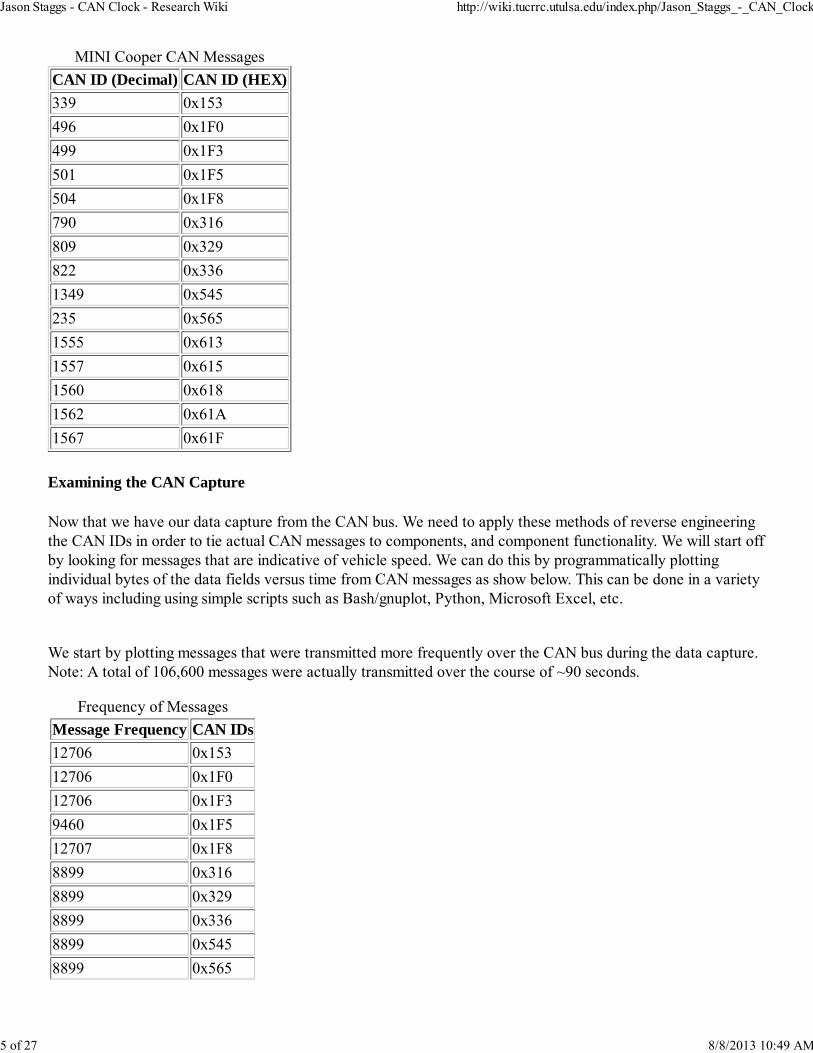
Examining the CAN Capture
Now that we have our data capture from the CAN bus. We need to apply these methods of reverse engineeringthe CAN IDs in order to tie actual CAN messages to components, and component functionality. We will start offby looking for messages that are indicative of vehicle speed. We can do this by programmatically plottingindividual bytes of the data fields versus time from CAN messages as show below. This can be done in a varietyof ways including using simple scripts such as Bash/gnuplot, Python, Microsoft Excel, etc.
We start by plotting messages that were transmitted more frequently over the CAN bus during the data capture.Note: A total of 106,600 messages were actually transmitted over the course of ~90 seconds.
Frequency of Messages
Message Frequency CAN IDs
12706 0x153
12706 0x1F0
12706 0x1F3
9460 0x1F5
12707 0x1F8
8899 0x316
8899 0x329
8899 0x336
8899 0x545
8899 0x565
Jason Staggs - CAN Clock - Research Wiki http://wiki.tucrrc.utulsa.edu/index.php/Jason_Staggs_-_CAN_Clock
5 of 27 8/8/2013 10:49 AM

433 0x613
433 0x615
433 0x618
434 0x61A
87 0x61F
*Message ID 0x153 The images below were produced using a Python script(link to Dr. Daily's script) that isdesigned to parse the CAN data log produced by the Gryphon S3.
Jason Staggs - CAN Clock - Research Wiki http://wiki.tucrrc.utulsa.edu/index.php/Jason_Staggs_-_CAN_Clock
6 of 27 8/8/2013 10:49 AM

Jason Staggs - CAN Clock - Research Wiki http://wiki.tucrrc.utulsa.edu/index.php/Jason_Staggs_-_CAN_Clock
7 of 27 8/8/2013 10:49 AM

As we can see, message ID 0x153 byte 2 of the data field shows a consistent increase over the duration of thecapture during the staged auto collision which lasted roughly 90 seconds. This increase is most indicative of
Jason Staggs - CAN Clock - Research Wiki http://wiki.tucrrc.utulsa.edu/index.php/Jason_Staggs_-_CAN_Clock
8 of 27 8/8/2013 10:49 AM

vehicle speed, as we know with external instrument measurements that the speed of the MINI Cooper justbefore impact was nearing 30 MPH. Note: Other messages were also found to be indicative of vehicle speed,these messages were likely from individual wheel sensors. However, these messages were not responsible forcontrolling the speedometer directly.
*CAN message used to manipulate
speedometer.
Now that we have identified the message ID and byte offset for vehicle speed, we need to isolate the ID anddata fields for engine speed. Because the MINI Cooper was propelled with a pulley system in the staged crash inwhich the data log was recorded, the actual engine speed was at a constant idle speed throughout the capture.Because of the engine speed being idle during the experiment, our previous method of visually identifyingmessage IDs based on data value against timestamps will be ineffective for identifying this message ID with thisdata set. Instead, we will use a data log capture from a previous test run of the MINI Cooper. In this test thedriver performed a variety of skid tests within the confines of a controlled environment. Below are the results ofthat data run in which we were able to visually identify engine like speed.
*Message ID 0x316
Jason Staggs - CAN Clock - Research Wiki http://wiki.tucrrc.utulsa.edu/index.php/Jason_Staggs_-_CAN_Clock
9 of 27 8/8/2013 10:49 AM

Jason Staggs - CAN Clock - Research Wiki http://wiki.tucrrc.utulsa.edu/index.php/Jason_Staggs_-_CAN_Clock
10 of 27 8/8/2013 10:49 AM

Jason Staggs - CAN Clock - Research Wiki http://wiki.tucrrc.utulsa.edu/index.php/Jason_Staggs_-_CAN_Clock
11 of 27 8/8/2013 10:49 AM
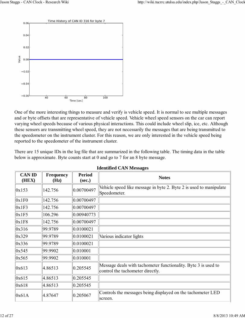
One of the more interesting things to measure and verify is vehicle speed. It is normal to see multiple messagesand or byte offsets that are representative of vehicle speed. Vehicle wheel speed sensors on the car can reportvarying wheel speeds because of various physical interactions. This could include wheel slip, ice, etc. Althoughthese sensors are transmitting wheel speed, they are not necessarily the messages that are being transmitted tothe speedometer on the instrument cluster. For this reason, we are only interested in the vehicle speed beingreported to the speedometer of the instrument cluster.
There are 15 unique IDs in the log file that are summarized in the following table. The timing data in the tablebelow is approximate. Byte counts start at 0 and go to 7 for an 8 byte message.
Identified CAN Messages
CAN ID(HEX)
Frequency(Hz)
Period(sec.)
Notes
0x153 142.756 0.00700497Vehicle speed like message in byte 2. Byte 2 is used to manipulateSpeedometer.
0x1F0 142.756 0.00700497
0x1F3 142.756 0.00700497
0x1F5 106.296 0.00940773
0x1F8 142.756 0.00700497
0x316 99.9789 0.0100021
0x329 99.9789 0.0100021 Various indicator lights
0x336 99.9789 0.0100021
0x545 99.9902 0.010001
0x565 99.9902 0.010001
0x613 4.86513 0.205545Message deals with tachometer functionality. Byte 3 is used tocontrol the tachometer directly.
0x615 4.86513 0.205545
0x618 4.86513 0.205545
0x61A 4.87647 0.205067Controls the messages being displayed on the tachometer LEDscreen.
Jason Staggs - CAN Clock - Research Wiki http://wiki.tucrrc.utulsa.edu/index.php/Jason_Staggs_-_CAN_Clock
12 of 27 8/8/2013 10:49 AM

0x61F 0.975293 1.02533 Tachometer along with various indicator lights.
CAN Clock Proof of Concept
In this section we describe the steps in creating/building the CAN Clock proof of concept that simulates theeffect an attacker could have on a vehicle, assuming she has physical access. In this demonstration we transformthe speedometer and a tachometer from a wrecked 2003 MINI Cooper S into a literal clock, where the hourswill be represented by the speedometer (0-120 MPH) and the minutes will be represented by the tachometer(0-6000 RPM). We build a CAN network with three physical CAN nodes. We generate CAN traffic by buildinga CAN ECU using an Arduino microcontroller, MCP1215 CAN controller, and MCP2551 CAN transceiver.
The following hardware, software, and tools were used to construct the CAN Clock:
Hardware Supplies
2003 Mini Cooper S instrument cluster module(IKE)"This is actually the unit housing the speedometer"2003 Mini Cooper S tachometerArduino Uno "Using REV 3 in this tutorial"CAN-BUS Shield for Arduino Uno "Available from sparkfun.com"2 x 120 ohms resistor18 gauge twisted pair wire "For CAN bus backbone"Wire nutsTie wraps12V DC power source2 x 1.5" x 1.625" x 1.25" brackets with bolts
Tools
Wire strippersSolderSoldering iron
Software
Python/BashMicrosoft Excel
Tutorial
Initially the hardware was mounted onto a self-contained board. For prototyping purposes a 18” x 14” woodboard was used to house the platform of the CAN Clock. Next, the MINI Cooper gauges were mounted usingbrackets, screws, and bolts.
Jason Staggs - CAN Clock - Research Wiki http://wiki.tucrrc.utulsa.edu/index.php/Jason_Staggs_-_CAN_Clock
13 of 27 8/8/2013 10:49 AM

Since BMW does not publicly disclose CAN message IDs for their various ECU devices on passenger vehicles,we applied our reverse engineering methodology described above. Using this methodology, we now have apretty solid idea of what message IDs and byte offsets are needed to control the display of the speedometer andtachometer on the instrument cluster. The next step is building a small CAN network and a CAN node capableof introducing messages onto the data bus. The first thing we need to do is build the CAN bus infrastructure. Inadhering to the CAN standard, we used about 18 inches of 18 gauge twisted pair wire for the actual CAN busbackbone.
Jason Staggs - CAN Clock - Research Wiki http://wiki.tucrrc.utulsa.edu/index.php/Jason_Staggs_-_CAN_Clock
14 of 27 8/8/2013 10:49 AM

We also terminate both ends of the twisted pair wire by using 120 Ω terminating resistors at each end to reducereflection.
We now have the CAN bus backbone built and ready to add nodes onto it. Next we attach the MINI Cooperinstrument cluster (which includes both the speedometer and tachometer) onto the network via its CAN datalines. When attempting to modify hardware that is either unfamiliar or unknown, the first thing that should bedone is referencing the electrical schematics, if they are available. In this case we were able to utilize the MINICooper electrical schematics from Mitchell (www.prodemand.com). Mitchell maintains an enormous repositoryfull of vehicle service manuals, diagnostic codes, and wiring schematics for a majority of passenger vehicles.Leveraging this information was necessary for identifying the wires coming off of the instrument cluster units.
Jason Staggs - CAN Clock - Research Wiki http://wiki.tucrrc.utulsa.edu/index.php/Jason_Staggs_-_CAN_Clock
15 of 27 8/8/2013 10:49 AM

Instrument Cluster Circuit
The wires of interest have been highlighted in the image below.
Wires associated with power
Wire 1 BRN/BLK = GroundWire 2 VIO/BLK = 12V powersource(HOT IN ACCY, RUN ANDSTARTWire 3 BLK/VIO = 12V powersource(HOT IN START)Wire 15 RED/YEL = 12V powersource(HOT AT ALL TIMES)Wire 16 GRN/BLU = 12V powersource(HOT IN ON OR START)
CAN data lines
Wire 13 YEL/BRN = CAN-LWire 26 YEL/BLK = CAN-H
Once these wires were individuallyidentified, we striped the wires, spliced, andsoldered them together accordingly. Westriped the ends off of the 12V DC powersource and tied wires 2, 3, 15, and 16 of theinstrument cluster unit to the positive lead ofour power source (See images below). Wealso tied Wire 1 (ground) to the negativelead on our power supply. Next we connected the CAN high and low data lines to the network. We splice wires
Jason Staggs - CAN Clock - Research Wiki http://wiki.tucrrc.utulsa.edu/index.php/Jason_Staggs_-_CAN_Clock
16 of 27 8/8/2013 10:49 AM

13 and 26 from our instrument cluster into the CAN bus. Notice in the images below, CAN low is the blue wireof the CAN bus, and CAN high is the tan. After capping our wire leads to both power source and splicing CANnode entry points, we can plug in the power source to test that the instrument cluster powers on and worksproperly. If all goes correctly, a chime can be heard as soon as power is applied.
Jason Staggs - CAN Clock - Research Wiki http://wiki.tucrrc.utulsa.edu/index.php/Jason_Staggs_-_CAN_Clock
17 of 27 8/8/2013 10:49 AM

Now that the instrument cluster has successfully been connected to the CAN bus, we can configure the nodethat will be responsible for transmitting data to the instrument cluster unit. This node will be acting as a roguedevice that an attacker could use to interact with other components on the CAN bus in nefarious ways. We willbe using an Arduino Uno Rev 3 and a CAN-Shield to achieve this.
Jason Staggs - CAN Clock - Research Wiki http://wiki.tucrrc.utulsa.edu/index.php/Jason_Staggs_-_CAN_Clock
18 of 27 8/8/2013 10:49 AM

To interface the CAN shield with the data bus, we splice the 18 gauge twisted pair wire from the CAN bus andsolder CAN-H and CAN-L wires coming into the pins on the CAN shield.
Jason Staggs - CAN Clock - Research Wiki http://wiki.tucrrc.utulsa.edu/index.php/Jason_Staggs_-_CAN_Clock
19 of 27 8/8/2013 10:49 AM

The Arduino will be powered from the same 12V DC power source that powers the instrument cluster. TheArduino Uno features a built in voltage regulator at the power port. Considering the safety benefit of the voltageregulator, applying 12V of power to the Arduino was not an issue as the Arduino Uno specifications explicitlystate that the microcontroller can handle a recommended 7 - 12 volts.
Jason Staggs - CAN Clock - Research Wiki http://wiki.tucrrc.utulsa.edu/index.php/Jason_Staggs_-_CAN_Clock
20 of 27 8/8/2013 10:49 AM
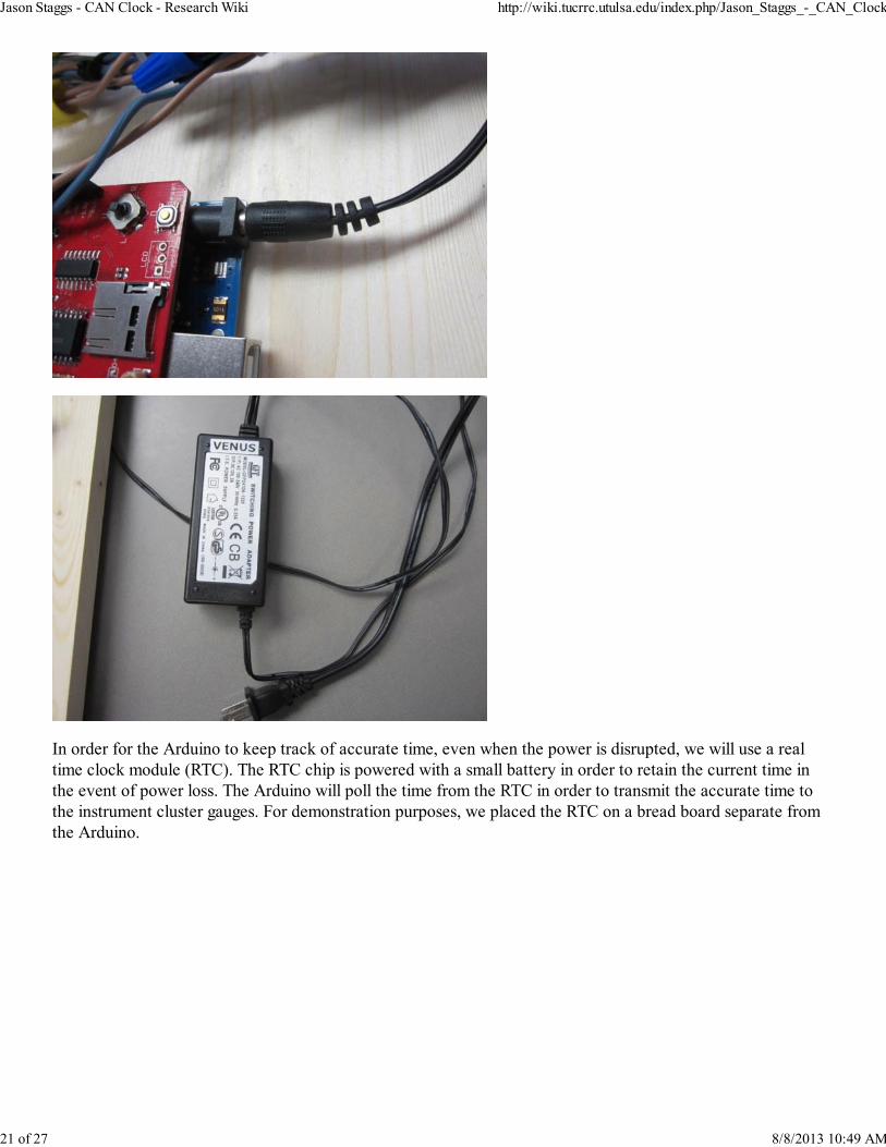
In order for the Arduino to keep track of accurate time, even when the power is disrupted, we will use a realtime clock module (RTC). The RTC chip is powered with a small battery in order to retain the current time inthe event of power loss. The Arduino will poll the time from the RTC in order to transmit the accurate time tothe instrument cluster gauges. For demonstration purposes, we placed the RTC on a bread board separate fromthe Arduino.
Jason Staggs - CAN Clock - Research Wiki http://wiki.tucrrc.utulsa.edu/index.php/Jason_Staggs_-_CAN_Clock
21 of 27 8/8/2013 10:49 AM

Everything up to this point should be connected, and all that should be left is to program the microcontroller.Other than the standard Arduino libraries, we will primarily be using the MCP2515 library to communicate withthe CAN controller, and SPI library to communicate with the CAN shield using the serial peripheral interface.The MCP2515 library allows us to construct our own CAN Frame objects that can be injected onto the CANbus. We will also be using the Wire.h and RTClib.h libraries to communicate with the RTC module.
For purposes of demonstration, the microcontroller was configured to work in two modes of operation that caneasily be toggled by using the joystick click button on the CAN-Shield; Clock Mode, and Demo Mode (Seeimages below). Clock mode obviously polls the time from the RTC to display the current time on the instrumentcluster gauges via the CAN bus, and demo mode is used to increment the needles on the gauges arbitrarily todemonstrate the dynamic manipulation of CAN traffic. The final product (CAN Clock) is shown below showinga time of 2:47 p.m.
Jason Staggs - CAN Clock - Research Wiki http://wiki.tucrrc.utulsa.edu/index.php/Jason_Staggs_-_CAN_Clock
22 of 27 8/8/2013 10:49 AM

Jason Staggs - CAN Clock - Research Wiki http://wiki.tucrrc.utulsa.edu/index.php/Jason_Staggs_-_CAN_Clock
23 of 27 8/8/2013 10:49 AM
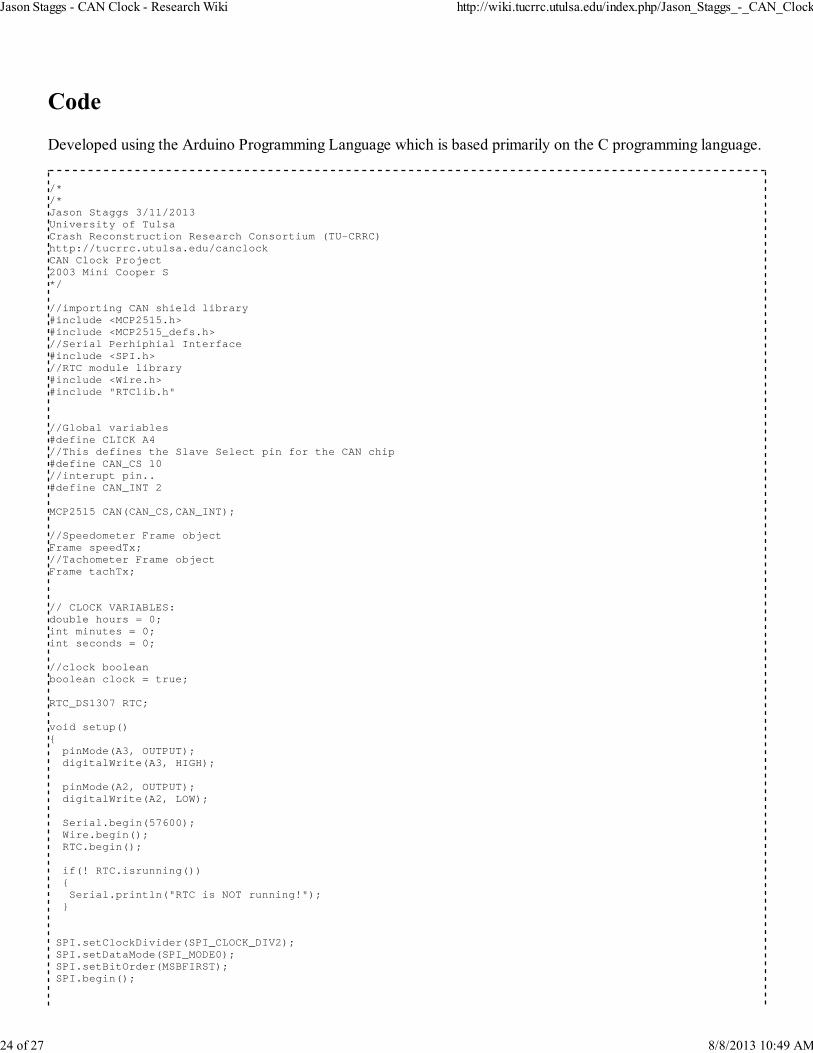
Developed using the Arduino Programming Language which is based primarily on the C programming language.
/*/*Jason Staggs 3/11/2013University of TulsaCrash Reconstruction Research Consortium (TU-CRRC)http://tucrrc.utulsa.edu/canclockCAN Clock Project2003 Mini Cooper S*/
//importing CAN shield library#include <MCP2515.h> #include <MCP2515_defs.h>//Serial Perhiphial Interface#include <SPI.h>//RTC module library#include <Wire.h>#include "RTClib.h"
//Global variables#define CLICK A4//This defines the Slave Select pin for the CAN chip#define CAN_CS 10//interupt pin..#define CAN_INT 2
MCP2515 CAN(CAN_CS,CAN_INT);
//Speedometer Frame objectFrame speedTx;//Tachometer Frame objectFrame tachTx;
// CLOCK VARIABLES:double hours = 0;int minutes = 0;int seconds = 0;
//clock booleanboolean clock = true;
RTC_DS1307 RTC;
void setup() pinMode(A3, OUTPUT); digitalWrite(A3, HIGH); pinMode(A2, OUTPUT); digitalWrite(A2, LOW); Serial.begin(57600); Wire.begin(); RTC.begin();
if(! RTC.isrunning()) Serial.println("RTC is NOT running!"); SPI.setClockDivider(SPI_CLOCK_DIV2); SPI.setDataMode(SPI_MODE0); SPI.setBitOrder(MSBFIRST); SPI.begin();
Jason Staggs - CAN Clock - Research Wiki http://wiki.tucrrc.utulsa.edu/index.php/Jason_Staggs_-_CAN_Clock
24 of 27 8/8/2013 10:49 AM

int baudRate=CAN.Init(500,16); if(baudRate>0) Serial.println("MCP2515 Init OK ..."); Serial.print("Baud Rate (kbps): "); Serial.println(baudRate,DEC); else Serial.println("MCP2515 Init Failed ..."); Serial.println("Initialization Complete."); //enable rollover...? CAN.BitModify(RXB0CTRL,0x04,0x04);
pinMode(CLICK,INPUT); digitalWrite(CLICK, HIGH);
void loop() //runTest(); if(clock) clockMode(); if(digitalRead(CLICK) == 0 || clock == false) clock = false; demoMode(); if(clock == false && digitalRead(CLICK) == 0) clock = true;
void clockMode() DateTime now = RTC.now(); hours = now.hour(); minutes = now.minute(); seconds = now.second(); if(hours > 12) hours = hours - 12; if(hours == 0) hours = 12; //fun action for hours if(minutes == 00 && seconds < 3) hours = 15; //Scale from program value to dial value hours = (hours + ((double)minutes / 60)) * 7.9; //fun action for minutes //scale minutes if(seconds < 3) minutes = 80; minutes = minutes *2.5; speedTx.id = 0x153; speedTx.srr = 0x0; speedTx.rtr = 0x0; speedTx.dlc = 0x8; speedTx.data[2] = hours; //Sending the frame on its way
Jason Staggs - CAN Clock - Research Wiki http://wiki.tucrrc.utulsa.edu/index.php/Jason_Staggs_-_CAN_Clock
25 of 27 8/8/2013 10:49 AM

CAN.LoadBuffer(TXB0,speedTx); CAN.SendBuffer(TXB0); delay(5); tachTx.id = 0x316; tachTx.srr = 0x0; tachTx.rtr = 0x0; tachTx.dlc = 0x8; tachTx.data[3] = minutes; //Sending the frame on its way CAN.LoadBuffer(TXB0,tachTx); CAN.SendBuffer(TXB0); delay(80);
void demoMode() speedTx.id = 0x153; speedTx.srr = 0x0; speedTx.rtr = 0x0; speedTx.dlc = 0x8; speedTx.data[2] = hours; //Sending the frame on its way CAN.LoadBuffer(TXB0,speedTx); CAN.SendBuffer(TXB0); hours++; if(hours > 95) hours = 0; delay(5); tachTx.id = 0x316; tachTx.srr = 0x0; tachTx.rtr = 0x0; tachTx.dlc = 0x8; tachTx.data[3] = minutes; //Sending the frame on its way CAN.LoadBuffer(TXB0,tachTx); CAN.SendBuffer(TXB0); minutes++; delay(5); if(minutes > 150) minutes = 0; delay(80);
ProDemand (Mitchell Repair Information Company): https://www.prodemand.com/Arduino API documentation: http://arduino.cc/en/Reference/HomePage/Python API documentation: http://www.python.org/doc/Good introductory book to CAN: http://www.amazon.com/Comprehensible-Guide-Controller-Area-Network/dp/0976511606/ref=sr_1_2?ie=UTF8&qid=1362956577&sr=8-2&keywords=CAN+busEasy to read/comprehend intro to the CAN standard: http://www.ti.com/lit/an/sloa101a/sloa101a.pdfGNU Plot: http://www.gnuplot.info/
Retrieved from "http://wiki.tucrrc.utulsa.edu/index.php?title=Jason_Staggs_-_CAN_Clock&oldid=2937"
Jason Staggs - CAN Clock - Research Wiki http://wiki.tucrrc.utulsa.edu/index.php/Jason_Staggs_-_CAN_Clock
26 of 27 8/8/2013 10:49 AM

This page was last modified on 29 July 2013, at 12:58.This page has been accessed 181 times.
Jason Staggs - CAN Clock - Research Wiki http://wiki.tucrrc.utulsa.edu/index.php/Jason_Staggs_-_CAN_Clock
27 of 27 8/8/2013 10:49 AM