jci paper #32012 seismic design specifications for seismic retrofit has been firstly targeted to...
TRANSCRIPT

Evaluation of Limit States of RC Columns in Performance-Based
Seismic Design of Bridges
Jun-ichi Hoshikuma
Center for Advanced Engineering StructuralAssessment and Research (CAESAR)
Public Works Research Institute
What’ is the Public Works Research Institute
Public Works Research Institute is one of Japanese representative research institutes under MLIT (Ministry of Land, Infrastructure, Transport and Tourism) jurisdiction.
PWRI’s mission is to develop public works technologies including prevention/mitigation of natural disasters, improvement of living environment, new materials/construction methods etc.
・ Collection of Data of Design, Construction, Maintenance of Bridges and Damage/Trouble Experiences
・ Technical Counsel for Bridge Administrators・ Technical Emergency Assistance for Bridge Administrators after
Disaster and Accidents
Advanced Researches for On-site Technical Needs of Bridges
Researches for Development of Design Criteria・ Investigation of Cause of Damage and Trouble with Bridges・ Clarification of Lessons Learned form Damage and Trouble Experiences ・ Study of Prevention or Mitigation of Damage and Development of
Design Criteria, Construction Manual for Bridges ・ Clinical Research Approach with Decommissioned Bridge Elements
Center for Advanced Engineering StructuralAssessment and Research
Center for Advanced Engineering StructuralAssessment and Research
Earthquake Engineering Research Team Development of Seismic Design Methods for Bridges Assessment of Seismic Performance of Existing Bridges Development of Seismic Retrofit Technique for Existing Bridges
Seismic Performance for Bridges in Japan
Type of Ground Motion
Level 1 EQHigh Probability to Occur
SPL 1: Undamaged to befully operational
Type-I EQInterplate
(Kanto EQ)Level 2 EQLow Probability to Occur
Type-II EQNear-fault(Kobe EQ)
Class-A(Standard Br.)
Class-B(Important Br.)
SPL 3:Prevent critical damage
SPL 2:Retain limited damage to recover ope-ration soon
Importance
Required seismic performance for bridges specified by MLIT 2012 Interplate EQ(cIz=1.0)2012 Interplate EQ(cIz=1.2)
.1 10.2 0.5 2 530
0
0.1 10.2 0.5 2 5300
00
0.1 10.2 0.5 2 53Natural Period T (s)
Standard Design Response Spectra (m/s2)
Soil Profile Type I Soil Profile Type II Soil Profile Type III
2002 Interplate EQNear-Fault EQ
50
30
20
10
75
3
2
10.1
Standard Design Response Spectra
JCI Paper #3

Design earthquake ground motion (Type-I) corresponding to interplate earthquakes zones was revised with consideration of the 2011 great east Japan earthquake & the anticipated great earthquake along the Nankai Trough.
Structural planning for bridges with the risk of tsunami inundation
Clarification of Requirements for seismic structural elementsof bridges
Recent research accomplishments on seismic design limit state of structural elements
Revised in 2012 based on knowledge derived from recent extreme earthquakes and research accomplishments
Latest Revision of Seismic Design Criteria
2011 Great East Japan EQ
M9 EQs were taken into account for revision of Cz.
Major Interplate Earthquakes near Japan
9
cIz cIIz1.2 1.0
1.0 1.0
1.2 0.85
1.0 0.85
0.8 0.7
cIz : Interplate EQ.cIIz : Near fault EQ.
Seismic Risk Hazard Map (Zone Factor Cz)
SPL Safety ServiceabilityRepairability
Short Term Long TermSPL 1: Prevent Damage
Prevent Unseating of Superstructure
Same Function as before Earthquake
Needless of Repair for Function Recovery
Simple Repair Work
SPL 2: Limited Damage for Function Recovery
Prevent Unseating of Superstructure
Possible Early Function Recovery
Function Recovery by Temporary Repair
Possible Permanent Repair Work
SPL 3:Prevent Critical Damage
Prevent Unseating of Superstructure
Seismic Performance Level for Bridges
11
Rubber Bearing
Bearing: Elastic Limit
Columns: RepairableLimit
Abutment: Elastic Limit
Foundation: Limited Nonlinear Behavior
Footing: Elastic Limit
General Continuous Multi-Span Bridge
Engineering Limit States of Bridge System to Satisfy Requirement of SPL2
12
Superstructure: Limited Nonlinear BehaviorAbutment:
Elastic Limit
Column: Repairable Limit
→ Support Live Load Directly / Difficult to repair
Foundation: Limited Nonlinear Behavior
Engineering Limit States of Bridge System to Satisfy Requirement of SPL2
Frame-type PC Bridge
JCI Paper #3

Cyclic Loading Test for Full Scale Model
1/2 Scale Model
1/4 Scale Model
Experimental Verification for RC Columns
水 平 力
水 平 変 位
耐 震 性 能 1耐 震 性 能 2 耐 震 性 能 3
耐 震 性 能 1に 対 す る限 界 状 態
耐 震 性 能 2に 対 す る限 界 状 態
耐 震 性 能 3に 対 す る限 界 状 態
SPL3SPL2SPL1
Lateral displacement
Late
ral F
orce
Limit state for SPL1
Limit state for SPL2
Limit state for SPL3
Engineering Limit States for RC Columns
水平力
水平変位
1) 2) 3)4)
1) Flexural cracksYielding of rebar
2) Residual cracksStable hysteresis loop
3) Onset of Buckling of rebarDegradation of lateralforce during cyclic loading
4) Onset of Fracture of rebar
LateralDisplacement
Lateral force
Damage Observation of RC Bridge Column
Limit State for SP2
Limit State for SP3
Tension
Compression
Strain
Stress
Limit State of RC columns for SP2 is represented by tensile strain of longitudinal rebars.
Strain distributionStrain distribution
Lateral Displacement
Late
ral
Forc
e
Stress-strain of rebar
Compression Tension Tension
Compression
Rebar buckling occurs in compressive loading step after tensile loading
Buckling Behavior in Plastic Hinge
Ultimate Strength
Allowable Displacement
ls:Curvature at design limit state at base sectiony:Yield curvature at base sectionLp:Plastic hinge length
hMP ls
u
2/ppylsyls LhL
Plastic Deformation
Evaluation of Limit State for SP2 & SP3
Section Size:2.4×2.4 m
600m
m
Lp= 0.5D
ConventionalEquation
1.2
m
Buckling Behavior of Longitudinal RebarProperties of rebar
・ Resistance of hoops・ Resistance of cover concrete
3/16/15.9 nsypL
in which Lp ≦ 0.15h
n
sy ’
ProposedEquation
779
mm
Evaluation of Plastic Hinge Length
JCI Paper #3
sy
s=Ess
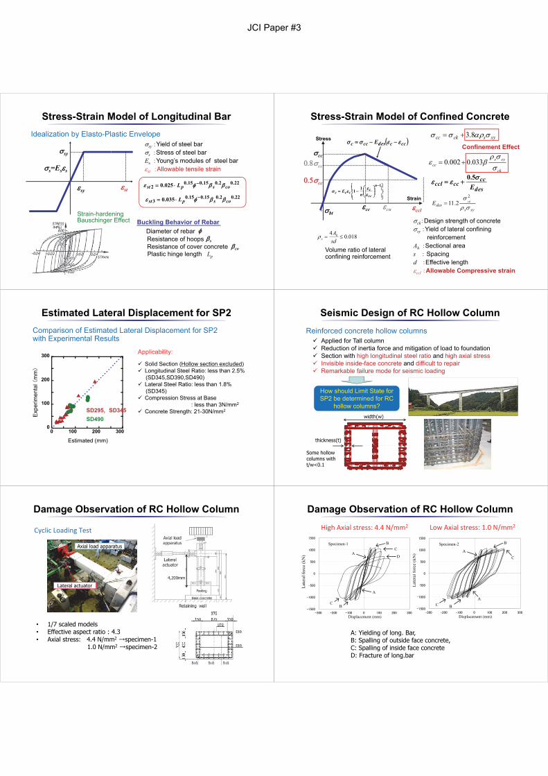
sy :Yield of steel bars :Stress of steel barEs :Young’s modules of steel barst :Allowable tensile strain
Idealization by Elasto-Plastic Envelope
Strain-hardeningBauschinger Effect
sy st22.02.015.015.0
2 025.0 cospst L
22.02.015.015.03 035.0 cospst L
Buckling Behavior of RebarDiameter of rebarResistance of hoopsResistance of cover concretePlastic hinge length Lp
s
co
Stress-Strain Model of Longitudinal Bar
Confinement Effectsysckcc 8.3
ck
syscc
033.0002.0
018.04
sdAh
s
Volume ratio of lateral confining reinforcement
ck:Design strength of concretesy :Yield of lateral confining
reinforcementAh :Sectional area s : Spacing d :Effective length ccl :Allowable Compressive strain
sysdes
ckE 2
2.11
cc
ccbt
cc
cccdesccc E
111
n
ccc
ccc nE
cu
cc
ccl
Stress
Strain
descc
ccccl E
5.0
Stress-Strain Model of Confined Concrete
0
100
200
300
0 100 200 300
Exp
erim
enta
l (m
m)
Estimated (mm)
SD490 SD295, SD345
Estimated Lateral Displacement for SP2Comparison of Estimated Lateral Displacement for SP2 with Experimental Results
Applicability:
Solid Section (Hollow section excluded) Longitudinal Steel Ratio: less than 2.5%
(SD345,SD390,SD490) Lateral Steel Ratio: less than 1.8%
(SD345) Compression Stress at Base
: less than 3N/mm2
Concrete Strength: 21-30N/mm2
Reinforced concrete hollow columns
Seismic Design of RC Hollow Column
Applied for Tall column Reduction of inertia force and mitigation of load to foundation Section with high longitudinal steel ratio and high axial stress Invisible inside-face concrete and difficult to repair Remarkable failure mode for seismic loading
How should Limit State for SP2 be determined for RC
hollow columns?width(w)
thickness(t)
Some hollow columns with t/w<0.1
Lateral actuator
Axial load apparatus
• 1/7 scaled models• Effective aspect ratio : 4.3• Axial stress: 4.4 N/mm2 →specimen-1
1.0 N/mm2 →specimen-2
Damage Observation of RC Hollow Column
Cyclic Loading Test
-1500
-1000
-500
0
500
1000
1500
-300 -200 -100 0 100 200 300
Late
ral f
orce
(kN
)
Displacement (mm)
Specimen-2
A
B
C
A C B
-1500
-1000
-500
0
500
1000
1500
-300 -200 -100 0 100 200 300Displacement (mm)
Late
ral f
orce
(kN
)
Specimen-1
A
B
A
B C
C
D
A: Yielding of long. Bar,B: Spalling of outside face concrete,C: Spalling of inside face concreteD: Fracture of long.bar
Damage Observation of RC Hollow ColumnHigh Axial stress: 4.4 N/mm2 Low Axial stress: 1.0 N/mm2
JCI Paper #3

• 3δ0 : No damage at inside, spalling of cover concrete at outside• 4δ0 : Buckling of long. steel bar arranged at both sides faces.
90 degree hook of cross-ties for inside face was unhooked, while135 degree hook for outside face was still hooked effectively.
Damage Observation of RC Hollow ColumnHigh Axial stress: 4.4 N/mm2
Damage Observation of RC Hollow ColumnHigh Axial stress: 1.0 N/mm2
• 4δ0 : No damage at inside, spalling of outside face cover concrete• 5δ0 : Onset of spalling of inside face cover concrete• 6δ0 : Buckling of long. steel bar arranged at both sides faces
90 degree hook of cross-ties for inside face was unhooked, while135 degree hook for outside face was still hooked effectively.
Structural Details of RC Hollow Column
Details of Reinforcement for Hollow Section
Solid Section
Haunch Section
Solid Section
Potential Plastic Hinge Region
Hoop for Corner Confinement
2012 Seismic Design Specifications for Highway Bridges Seismic Retrofit has been firstly targeted to prevent following failure modes observed during 1995 Kobe Earthquake.
Seismic Retrofit for RC Columns at Section of Cut-off of Longitudinal Rebars
Seismic Retrofit for Unseating Prevention System at Deck-end
Failure Modes Resulted in Fatal Damage
有効高さd 有効高さd
計算上不要となる部材断面
「十分な定着長」慣用的に重ね継ぎ手長la(軸方向鉄筋径φの30~35倍程度)
柱とフーチングの接合部や軸方向鉄筋量が大きく変化する位置(段落とし部など)では15cm程度
(一般の位置における規定量の2倍程度)
30cm程度(全高)
水平力
・d+20φ(折り曲げる時)
・鉄筋の引張応力度が 許容応力度の1/2以下 となる断面(下限値はla)
(伸ばす時)
水平力
30cm程度(一般部)
有効高さd 有効高さd
計算上不要となる部材断面
「十分な定着長」慣用的に重ね継ぎ手長la(軸方向鉄筋径φの30~35倍程度)
柱とフーチングの接合部や軸方向鉄筋量が大きく変化する位置(段落とし部など)では15cm程度
(一般の位置における規定量の2倍程度)
30cm程度(全高)
水平力
・d+20φ(折り曲げる時)
・鉄筋の引張応力度が 許容応力度の1/2以下 となる断面(下限値はla)
(伸ばす時)
水平力
30cm程度(一般部)
Before 1980 Design Code
1980 Design Code
300 mm Spacing
150 mm Spacing
150 mm spacingaround cut-offpoint
Development Length
Develop-ment
Length
300 mmSpacing
Revision of Reinforcement Details in 1980
Steel Jacketing for Pier Body and Unseating Prevention Devices
Seismic Retrofit for RC Columns at Section of Cut-off of Longitudinal Rebars
Seismic Retrofit for Unseating Prevention System at Deck-end
Concrete Jacketing for Pier Body and Unseating Prevention Devices
Damage experiences indicated the most vulnerable section in existing bridges designed in old Japanese codes.
Seismic Retrofit Strategy for Existing Bridges
JCI Paper #3

Retrofitted(Designated, Route 4)(3 3-span cont. girders)(Designed in 1974)
Damage at Cut-off Section Caused Bridge Close for about 3 Months.
Oshu city, IWATE
Trace of Seismic Behavior in Movable Bearing
Seismic Retrofit by RC Jacketing
Shear Crack
Retrofitted/Unretrofitted Bridge Piers Located Close Unretrofitted(Local Route)(9-span cont. girders)(Designed in 1972)
(Photo Provided from Tohoku Regional Development Bureau)
(Photo Provided from Tohoku Regional Development Bureau)
1995 Kobe EQ 2011 Great East Japan EQ
Research Projects in PWRIExperimental Researches for Seismic Retrofit
1982 Urakawa‐oki EQ
Seismic Retrofit Improved Seismic Performance Well
Retrofit
LESSONS
・Increase of Design Acceleration・ Improvement of Ductility
Revision
of
Design
Code
Unretrofitted
Unretrofitted Bridges Repeated Similar Damage Observed in Past EQs
Retrofitted Bridges Suffered Minor Damage except a Few Bridges
写真提供:茨城県
写真提供:茨城県
Extension of Seat Length Successfully Prevented Superstructure from Unseating!
2011 Great East Japan Earthquake
Reference: Ogasawara et., 67th JSCE Annual Meeting, VI-572, 2012.9
Released by Tohoku Regional Development Bureau, MLIT
Operation“TEETH OF COMB”
Route 4 and 11 east-west routes to coast area were serviceable to emergency vehicle up to March 12.Seismic retrofit for bridges in these important routes contributed to the quick recovery of highway network.
Resilient Design for Extreme Seismic Events
Seismic Assessment of Existing Foundation
Seismic Behavior of Foundation in Liquifiable Soil Based on Large-scale Shake Table Tests
Seismic Retrofit Technique with reducing post-anchored bars
Tsunami Effect on Bridges
Ongoing Seismic Research Project for Bridge
・ Damage-control approach to minimize the function damage
・ Capacity of Existing Piles and Evaluation of Limit State of Foundation
・ Seismic Retroifit of Foundation in Liquifiable Soil
・ Connection between Existing Section and Post-anchored Devices
・ Assessment of Existing Bridges for Tsunami-induced Force・Structural Planning for Mitigating Tsunami Effect on Bridges
JCI Paper #3