jennifer young gaudet - connecticut. the changes to the ... existing modcell 4.0 compact bts cabinet...
TRANSCRIPT
May 9, 2014 VIA OVERNIGHT DELIVERY
Ms. Melanie A. Bachman Acting Executive Director Connecticut Siting Council Ten Franklin Square New Britain, CT 06051 RE: Sprint Spectrum, L.P. – Notice of Exempt Modification 35 Old Route 44 (aka 34 Old Route 44), Eastford, CT Dear Ms. Bachman:
This letter and attachments are submitted on behalf of Sprint Spectrum, L.P. (“Sprint”). Sprint is undertaking modifications to certain existing sites in its Connecticut network in order to implement updated technology. In order to do so, Sprint will modify antenna and equipment configurations at a number of existing sites. Please accept this letter and attachments as notification, pursuant to R.C.S.A. Section 16-50j-73, of construction which constitutes an exempt modification pursuant to R.C.S.A Section 16-50j-72(b)(2). In compliance with R.C.S.A. Section 16-50j-73, a copy of this letter and attachments is being sent to the First Selectman of the Town of Eastford.
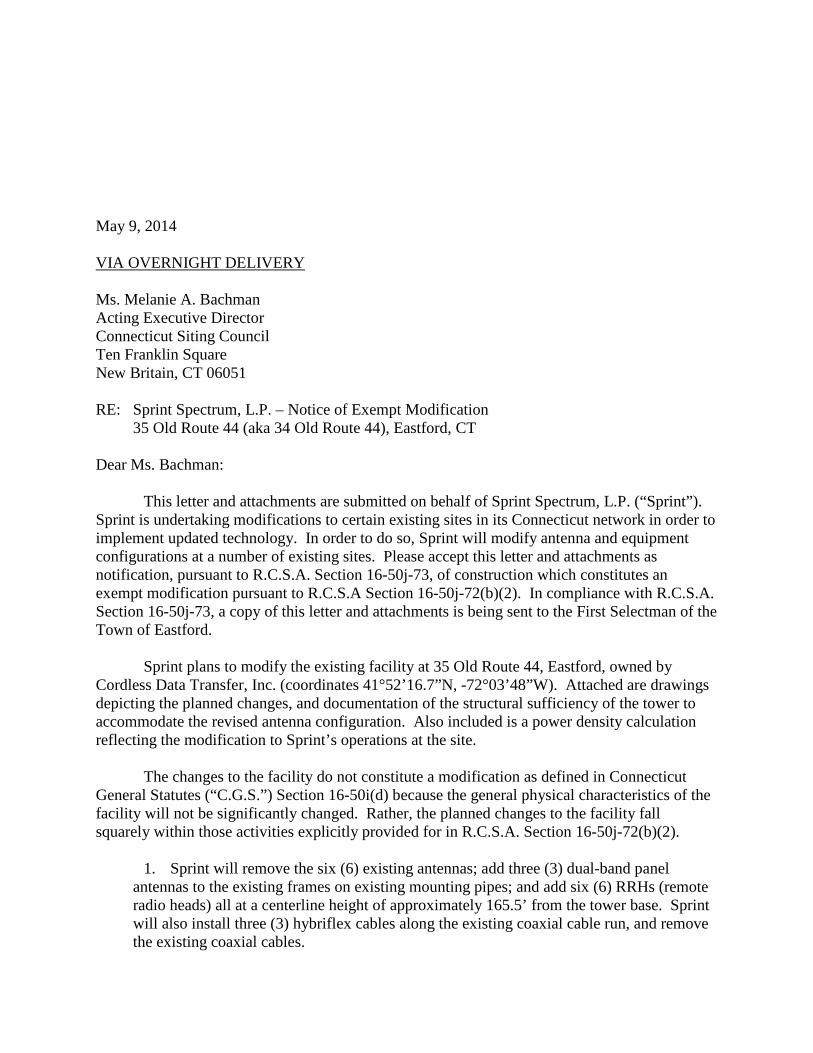
Sprint plans to modify the existing facility at 35 Old Route 44, Eastford, owned by Cordless Data Transfer, Inc. (coordinates 41°52’16.7”N, -72°03’48”W). Attached are drawings depicting the planned changes, and documentation of the structural sufficiency of the tower to accommodate the revised antenna configuration. Also included is a power density calculation reflecting the modification to Sprint’s operations at the site.
The changes to the facility do not constitute a modification as defined in Connecticut
General Statutes (“C.G.S.”) Section 16-50i(d) because the general physical characteristics of the facility will not be significantly changed. Rather, the planned changes to the facility fall squarely within those activities explicitly provided for in R.C.S.A. Section 16-50j-72(b)(2).
1. Sprint will remove the six (6) existing antennas; add three (3) dual-band panel
antennas to the existing frames on existing mounting pipes; and add six (6) RRHs (remote radio heads) all at a centerline height of approximately 165.5’ from the tower base. Sprint will also install three (3) hybriflex cables along the existing coaxial cable run, and remove the existing coaxial cables.
Ms. Melanie Bachman May 9, 2014 Page 2
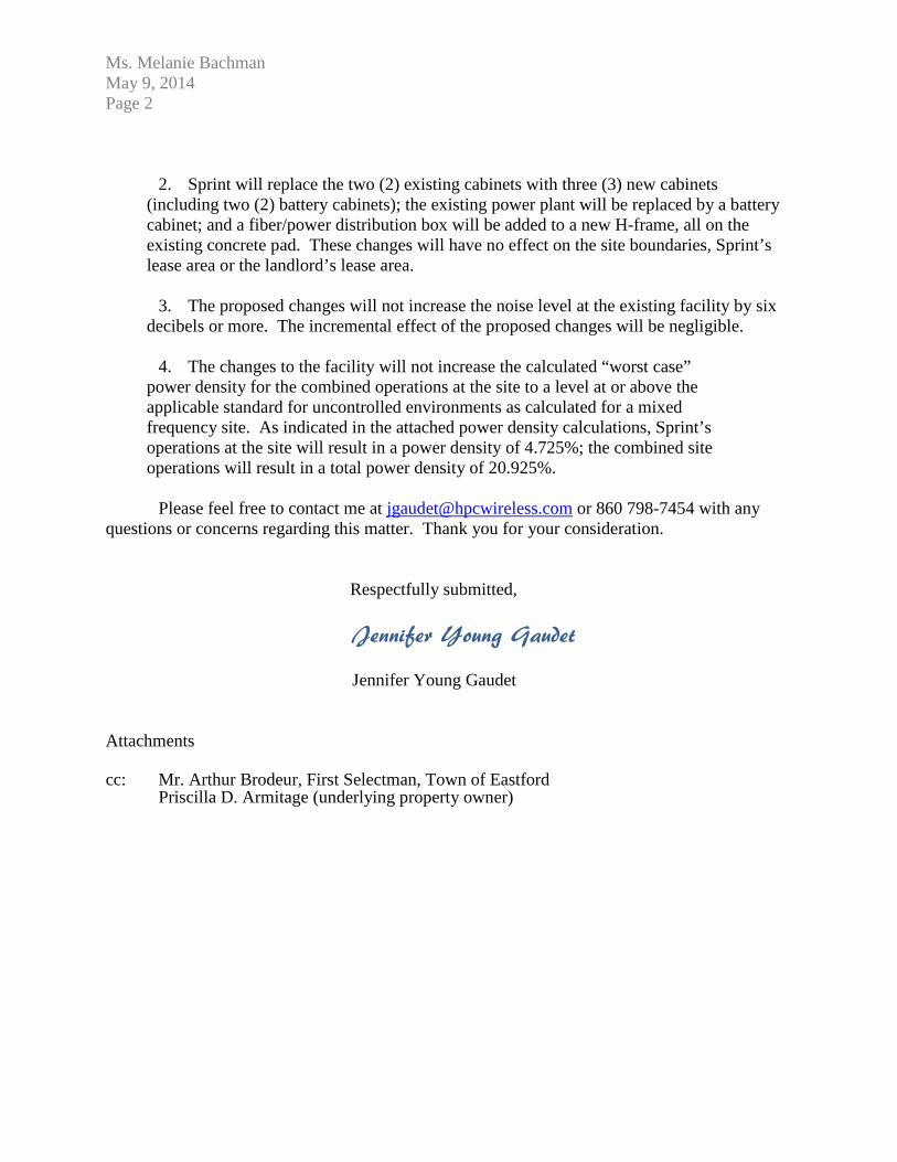
2. Sprint will replace the two (2) existing cabinets with three (3) new cabinets
(including two (2) battery cabinets); the existing power plant will be replaced by a battery cabinet; and a fiber/power distribution box will be added to a new H-frame, all on the existing concrete pad. These changes will have no effect on the site boundaries, Sprint’s lease area or the landlord’s lease area.
3. The proposed changes will not increase the noise level at the existing facility by six
decibels or more. The incremental effect of the proposed changes will be negligible. 4. The changes to the facility will not increase the calculated “worst case”
power density for the combined operations at the site to a level at or above the applicable standard for uncontrolled environments as calculated for a mixed frequency site. As indicated in the attached power density calculations, Sprint’s operations at the site will result in a power density of 4.725%; the combined site operations will result in a total power density of 20.925%.
Please feel free to contact me at [email protected] or 860 798-7454 with any
questions or concerns regarding this matter. Thank you for your consideration.
Respectfully submitted,
Jennifer Young Gaudet Jennifer Young Gaudet Attachments cc: Mr. Arthur Brodeur, First Selectman, Town of Eastford Priscilla D. Armitage (underlying property owner)

Ms. Melanie Bachman May 9, 2014 Page 2
16'-1
1"
EXISTIN
G 1
83'-0
"G
UYED
TOW
ER
EXISTIN
GSPR
INT
IDEN
SHELTER
EXISTIN
GVER
IZON
SHELTER
EXISTIN
GAT&T
SHELTER
EXISTIN
G S
PRIN
TIC
E BRID
GE
EXISTIN
G S
PRIN
TCO
NCRETE EQ
UIPM
ENT
PAD
WITH
ICE
CANO
PY ABO
VE
EXISTIN
G S
PRIN
TPPC
CABIN
ET
EXISTIN
G M
ETER B
ANK
GRAVEL
CO
MPO
UND
EXISTIN
G A
CCES
SG
ATE
EXISTIN
G FIB
ER TER
MIN
ATIO
NCABIN
ET ON H
-FRAM
E
EXISTIN
G C
HAIN
LINK FEN
CE
25'-8
"
14'-6"
EXISTIN
G S
PRIN
T OUTD
OO
R C
ABIN
ETSO
N S
TEEL PLINTH
MO
UNTED
ON
CO
NCRETE PA
D. S
EE SHEET A
-1 FO
RD
ETAILS
EXISTIN
G S
PRIN
T GPS
ANTEN
NA
GAMMAAZ 270°
BETAAZ 120°
ALPHA
AZ 340°
C-1
OVER
ALL S
ITE PLAN
SCALE: 1
" =
SITE PLA
N1
NO
RTH
CI:\22900\22974\CAD\Telecom\22974 Network Vision Project.dwg Printed by: cfoley on Feb 25, 2014 - 8:21am
SHEET
NUM
BER
PRO
JECT
NUM
BER
ISSUE
PHASE
DATE
ISSUED
MARK D
ATE D
ESCRIP
TIO
N
030'
15'
7.5
'
SHEET T
ITLE
:
PRO
JECT T
ITLE
:
PRO
JECT IN
FO
RM
ATIO
N:
NE
TWO
RK
VIS
ION
MM
BTS
LAU
NC
HN
OR
THE
RN
CT M
AR
KE
T
6391 Sprint P
arkway
Overland P
ark, KS
66251
A08.2
3PR
ELIM C
ONSTR
UCTIO
N D
RAW
ING
S
22974
EASTFO
RD
-CD
TSITE #: C
T33
XC0
16
34
OLD
RO
UTE 4
4EA
STFO
RD
, CT 0
62
42
FINAL PR
ELIMIN
ARY
02/2
4/2
014
A9/0
6/1
290%
CD
REVIE
W
B11/0
8/1
2FIN
AL P
RELIM
INARY C
D'S
C11/1
8/1
3G
M2 R
EVIS
IONS
D2/2
4/1
4RFD
S &
SCENARIO
124 R
EVs
VIC
INIT
Y M
AP
NO
RTH
GENERAL N
OTES:
1.
THE C
ONTR
ACTO
R S
HALL C
OM
PLY WITH
ALL A
PPLICABLE C
OD
ES O
RD
INANCES
, LAW
S,
AND
REG
ULA
TIONS O
F ALL M
UNIC
IPALITIES
, UTILITIES
CO
MPA
NY, O
R O
THER
PUBLIC
AUTH
ORITIES
.
2.
THE C
ONTR
ACTO
R S
HALL B
E RES
PONSIB
LE FOR O
BTA
ININ
G A
LL PERM
ITS A
ND
INSPEC
TIONS TH
AT M
AY B
E REQ
UIR
ED B
Y ANY FED
ERAL, S
TATE, C
OUNTY, O
RM
UNIC
IPAL A
UTH
ORITIES
.
3.
THE C
ONTR
ACTO
R S
HALL N
OTIFY TH
E CO
NSTR
UCTIO
N M
ANAG
ER, IN
WRITIN
G, O
F ANY
CO
NFLIC
TS, ER
RO
RS O
R O
MIS
SIO
NS PR
IOR TO
THE S
UBM
ISSIO
N O
F BID
S O
RPER
FORM
ANCE O
F WO
RK. M
INO
R O
MIS
SIO
NS O
R ER
RO
RS IN
THE B
ID D
OCUM
ENTS
SHALL N
OT R
ELIEVE TH
E CO
NTR
ACTO
R FR
OM
RES
PONSIB
ILITY FOR TH
E OVER
ALL
INTEN
T OF TH
ESE D
RAW
ING
S.
4.
THE C
ONTR
ACTO
R S
HALL B
E RES
PONSIB
LE FOR PR
OTEC
TING
ALL EXIS
TING
SITE
IMPR
OVEM
ENTS
PRIO
R TO
CO
MM
ENCIN
G C
ONSTR
UCTIO
N. TH
E CO
NTR
ACTO
R S
HALL
REPA
IR A
NY D
AM
AG
E CAUSED
AS A
RES
ULT O
F CO
NSTR
UCTIO
N O
F THE FA
CILITY.
5.
THE S
CO
PE OF W
ORK FO
R TH
IS PR
OJEC
T SHALL IN
CLU
DE PR
OVID
ING
ALL M
ATER
IALS
,EQ
UIPM
ENT, A
ND
LABO
R R
EQUIR
ED TO
CO
MPLETE TH
IS PR
OJEC
T. ALL EQ
UIPM
ENT
SHALL B
E INSTA
LLED IN
ACCO
RD
ANCE W
ITH TH
E MANUFA
CTU
RER
'SREC
OM
MEN
DATIO
NS.
6.
THE C
ONTR
ACTO
R S
HALL V
ISIT TH
E PRO
JECT S
ITE PRIO
R TO
SUBM
ITTING
A B
ID TO
VER
IFY THAT TH
E PRO
JECT C
AN B
E CO
NSTR
UCTED
IN A
CCO
RD
ANCE W
ITH TH
ECO
NTR
ACT D
OCUM
ENTS
.
7.
CO
NTR
ACTO
R S
HALL V
ERIFY A
NTEN
NA ELEV
ATIO
N A
ND
AZIM
UTH
WITH
RF EN
GIN
EERIN
GPR
IOR TO
INSTA
LLATIO
N.
8.
TRANSM
ITTER EQ
UIPM
ENT A
ND
ANTEN
NAS A
RE D
ESIG
NED
TO M
EET ANSI/EIA
/TIA 2
22-G
REQ
UIR
EMEN
TS.
9.
ALL S
TRUCTU
RAL ELEM
ENTS
SHALL B
E HO
T DIPPED
GALV
ANIZED
STEEL.
10.
CO
NTR
ACTO
R S
HALL M
AKE A
UTILITY "O
NE-C
ALL" TO
LOCATE A
LL UTILITIES
PRIO
R TO
EXCAVATIN
G.
11.
IF ANY U
ND
ERG
RO
UND
UTILITIES
OR S
TRUCTU
RES
EXIST B
ENEA
TH TH
E PRO
JECT A
REA
,CO
NTR
ACTO
R M
UST LO
CATE IT A
ND
CO
NTA
CT TH
E APPLIC
ANT & TH
E OW
NER
'SREPR
ESEN
TATIV
E.
12.
OCCUPA
NCY IS
LIMITED
TO PER
IOD
IC M
AIN
TENANCE A
ND
INSPEC
TION B
Y TECHNIC
IANS
APPR
OXIM
ATELY 2
TIMES
PER M
ONTH
.
13.
RAM
AKER
& ASSO
CIA
TES H
AS N
OT PER
FORM
ED A
STR
UCTU
RAL A
NALYS
IS FO
R TH
ISPR
OJEC
T. PRIO
R TO
THE IN
STA
LLATIO
N O
F THE PR
OPO
SED
EQUIPM
ENT O
RM
OD
IFICATIO
N O
F THE EXIS
TING
STR
UCTU
RE, A
STR
UCTU
RAL A
NALYS
IS S
HALL B
EPER
FORM
ED B
Y SPR
INT'S
AG
ENT TO
CER
TIFY THAT TH
E EXISTIN
G/PR
OPO
SED
CO
MM
UNIC
ATIO
N S
TRUCTU
RE A
ND
CO
MPO
NEN
TS A
RE S
TRUCTU
RALLY A
DEQ
UATE TO
SUPPO
RT A
LL EXISTIN
G A
ND
PRO
POSED
ANTEN
NAS, C
OAXIA
L CABLES
, AND
OTH
ERAPPU
RTEN
ANCES
.
14.
PRO
PERTY LIN
E INFO
RM
ATIO
N W
AS PR
EPARED
USIN
G D
EEDS, TA
X MAPS
, AND
PLANS
OF R
ECO
RD
AND
SHO
ULD
NO
T BE C
ONSTR
UED
AS A
N A
CCURATE B
OUND
ARY S
URVEY.
15.
THIS
PLAN IS
SUBJEC
T TO A
LL EASEM
ENTS
AND
RES
TRIC
TIONS O
F REC
ORD
.
16.
THE PR
OPO
SED
FACILITY W
ILL CAUSE O
NLY A
"DE M
INIM
IS" IN
CREA
SE IN
STO
RM
WATER
RUNO
FF; THER
EFORE, N
O D
RAIN
AG
E STR
UCTU
RES
ARE PR
OPO
SED
.
17.
NO
SIG
NIFIC
ANT N
OIS
E, SM
OKE, D
UST, O
R O
DO
R W
ILL RES
ULT FR
OM
THIS
FACILITY.
18.
THE FA
CILITY IS
UNM
ANNED
AND
NO
T INTEN
DED
FOR H
UM
AN H
ABITA
TION (N
OHAND
ICAP A
CCES
S R
EQUIR
ED).
19.
POW
ER TO
THE FA
CILITY W
ILL BE M
ONITO
RED
BY A
SEPA
RATE M
ETER.
WO
RK A
REA
EXISTIN
G A
CCES
SG
ATE
EXISTIN
G C
HAIN
LINK
FENCE
EXISTIN
G S
PRIN
T OUTD
OO
RCABIN
ETS O
N S
TEEL PLINTH
MO
UNTED
ON C
ONCRETE PA
D.
EXISTIN
G S
PRIN
T GPS
ANTEN
NA
EXISTIN
G S
PRIN
T CO
NCRETE
EQUIPM
ENT PA
D W
ITH IC
ECANO
PY ABO
VE
EXISTIN
G S
PRIN
TPPC
CABIN
ET
EXISTIN
G IC
E CANO
PY POST,(TYP).
EXISTIN
G M
OD
CELL 4
.0CO
MPA
CT B
TS C
ABIN
ET
EXISTIN
G D
C PO
WER
PLANT
4'-2
"
5'-4
"2'-7
"
6"2'-7
"
6'-4
"
2'-2
"
25'-8
"
2'-6"2'-11"
3'-0"
8'-5"
EXISTIN
GAT&T S
HELTER
EXISTIN
GAT&T S
HELTER
EXISTIN
G S
PRIN
TCO
NCRETE
EQUIPM
ENT
PAD
WITH
ICE
CANO
PY ABO
VE
EXISTIN
GACCES
S G
ATE
EXISTIN
G C
HAIN
LINK
FENCE
PRO
POSED
SPR
INT 9
928 M
M-B
TSCABIN
ET
EXISTIN
G S
PRIN
TPPC
CABIN
ET
EXISTIN
G S
PRIN
TIC
E BRID
GE
4'-2
"
4'-1
1"
3'-0
"
6"2'-7
"
6"
2'-2
"
25'-8
"
2'-7"
8'-5"
EXISTIN
G B
ASE S
TATIO
N TO
BE
"HO
T SW
APPED
" WITH
PRO
POSED
9928 M
M-B
TS C
ABIN
ET
PRO
POSED
39"x3
9"x1
2" N
EMA
3R FIB
ER/PO
WER
DIS
TRIB
UTIO
NBO
X MO
UNTED
TO N
EW PO
STS
.SEE D
ETAIL 3
/S-1
(2) PR
OPO
SED
60EC
v2 B
ATTER
YBACKUP C
ABIN
ETS2'-7
"3'-3
"
3'-2"2'-8"
(1) EXIS
TING
SPR
INT C
DM
A G
PSANTEN
NA TO
BE
REM
OVED
AND
REPLA
CED
WITH
(1)
PRO
POSED
PCTEL
GPS
ANTEN
NA
A-1
EQUIPM
ENT PLA
N
SCALE: 1
" = 7
.5'
EXISTIN
G EQ
UIPM
ENT PLA
N1
NO
RTH
SCALE: 1
" = 7
.5'
PRO
POSED
EQUIPM
ENT PLA
N2
NO
RTH
CI:\22900\22974\CAD\Telecom\22974 Network Vision Project.dwg Printed by: cfoley on Feb 25, 2014 - 8:21am
SHEET
NUM
BER
PRO
JECT
NUM
BER
ISSUE
PHASE
DATE
ISSUED
MARK D
ATE D
ESCRIP
TIO
N
015'
7.5
'3.7
5'
SHEET T
ITLE
:
PRO
JECT T
ITLE
:
PRO
JECT IN
FO
RM
ATIO
N:
NE
TWO
RK
VIS
ION
MM
BTS
LAU
NC
HN
OR
THE
RN
CT M
AR
KE
T
6391 Sprint P
arkway
Overland P
ark, KS
66251
A08.2
3PR
ELIM C
ONSTR
UCTIO
N D
RAW
ING
S
22974
EASTFO
RD
-CD
TSITE #: C
T33
XC0
16
34
OLD
RO
UTE 4
4EA
STFO
RD
, CT 0
62
42
FINAL PR
ELIMIN
ARY
02/2
4/2
014
A9/0
6/1
290%
CD
REVIE
W
B11/0
8/1
2FIN
AL P
RELIM
INARY C
D'S
C11/1
8/1
3G
M2 R
EVIS
IONS
D2/2
4/1
4RFD
S &
SCENARIO
124 R
EVs
EXISTIN
G ±
183
GUYED
TOW
ER
GRAD
E
EXISTIN
G S
PRIN
TEQ
UIPM
ENT PA
D
EXISTIN
G S
PRIN
T/NEXTEL
IDEN
SHELTER
EXISTIN
G V
ERIZO
NSHELTER EXIS
TING
VER
IZON A
NTEN
NAS
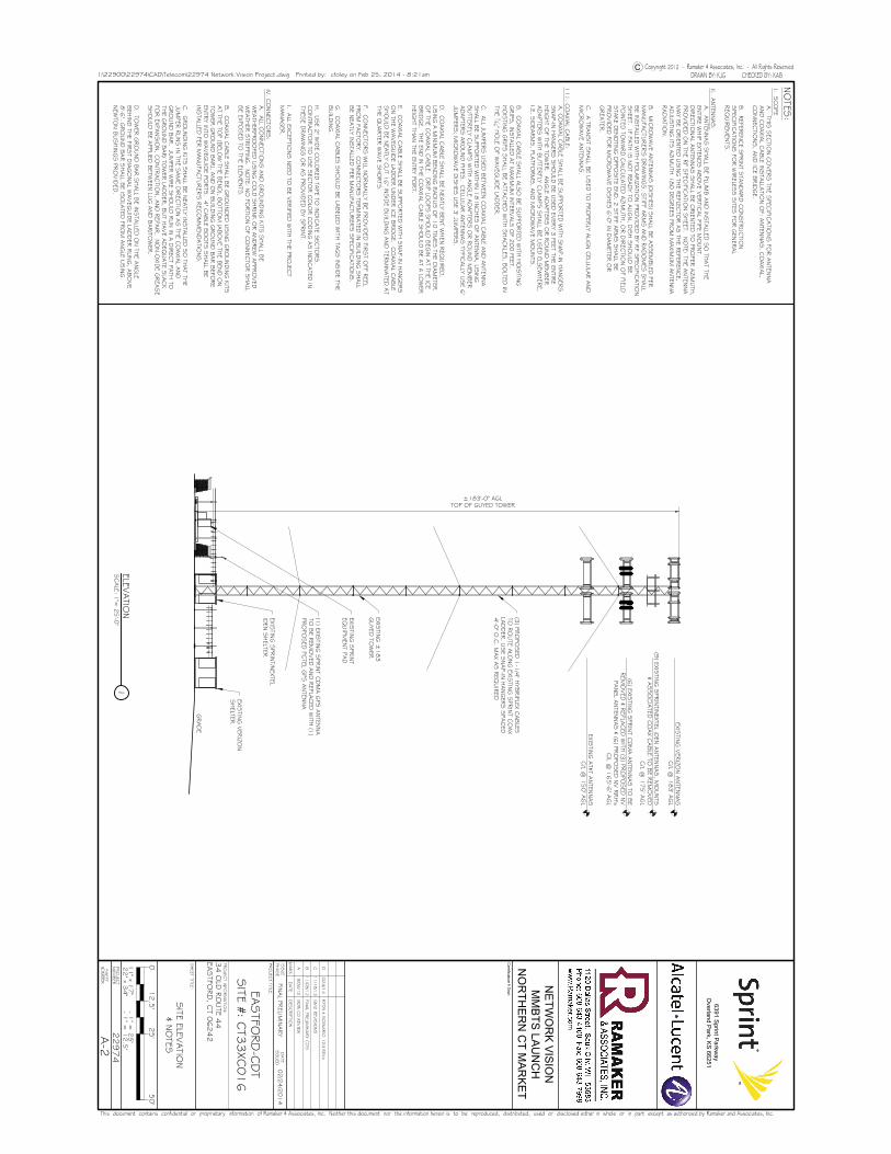
C/L @
183' A
GL
(9) EXIS
TING
SPR
INT/N
EXTEL iDEN
ANTEN
NAS, M
OUNTS
& ASSO
CIA
TED C
OAX C
ABLE TO
BE R
EMO
VED
C/L @
175' A
GL
(6) EXIS
TING
SPR
INT C
DM
A A
NTEN
NAS TO
BE
REM
OVED
& REPLA
CED
WITH
(3) PR
OPO
SED
NV
PANEL A
NTEN
NAS & (6
) PRO
POSED
NV R
RH's
C/L @
165'-6
" AG
L
±183'-0" AGLTOP OF GUYED TOWER
EXISTIN
G A
T&T ANTEN
NAS
C/L @
150' A
GL
(1) EXIS
TING
SPR
INT C
DM
A G
PS A
NTEN
NA
TO B
E REM
OVED
AND
REPLA
CED
WITH
(1)
PRO
POSED
PCTEL G
PS A
NTEN
NA
(3) PR
OPO
SED
1-1
/4" H
YBRIFLEX C
ABLES
TO R
OUTE A
LONG
EXISTIN
G S
PRIN
T CO
AX
LAD
DER
. USE S
NAP-IN
HANG
ERS S
PACED
4'-0
" O.C
. MAX A
S R
EQUIR
ED
A-2
SITE ELEV
ATIO
N& N
OTES
SCALE: 1
"= 2
5'-0
"ELEV
ATIO
N1
CI:\22900\22974\CAD\Telecom\22974 Network Vision Project.dwg Printed by: cfoley on Feb 25, 2014 - 8:21am
SHEET
NUM
BER
PRO
JECT
NUM
BER
ISSUE
PHASE
DATE
ISSUED
MARK D
ATE D
ESCRIP
TIO
N
050'
12.5
'25'
SHEET T
ITLE
:
PRO
JECT T
ITLE
:
PRO
JECT IN
FO
RM
ATIO
N:
NE
TWO
RK
VIS
ION
MM
BTS
LAU
NC
HN
OR
THE
RN
CT M
AR
KE
T
6391 Sprint P
arkway
Overland P
ark, KS
66251
A08.2
3PR
ELIM C
ONSTR
UCTIO
N D
RAW
ING
S
22974
EASTFO
RD
-CD
TSITE #: C
T33
XC0
16
34
OLD
RO
UTE 4
4EA
STFO
RD
, CT 0
62
42
FINAL PR
ELIMIN
ARY
02/2
4/2
014
A9/0
6/1
290%
CD
REVIE
W
B11/0
8/1
2FIN
AL P
RELIM
INARY C
D'S
C11/1
8/1
3G
M2 R
EVIS
IONS
D2/2
4/1
4RFD
S &
SCENARIO
124 R
EVs
I. SC
OPE
A. TH
IS S
ECTIO
N C
OVER
S TH
E SPEC
IFICATIO
NS FO
R A
NTEN
NA
AND
CO
AXIA
L CABLE IN
STA
LLATIO
N O
F: ANTEN
NAS, C
OAXIA
L,CO
NNEC
TIONS, A
ND
ICE B
RID
GE.
B. R
EFEREN
CE S
PRIN
T STA
ND
ARD
CO
NSTR
UCTIO
NSPEC
IFICATIO
NS FO
R W
IRELES
S S
ITES FO
R G
ENER
AL
REQ
UIR
EMEN
TS.
II. ANTENNAS:
A. A
NTEN
NAS S
HALL B
E PLUM
B A
ND
INSTA
LLED S
O TH
AT TH
EEN
TIRE W
HIP EXTEN
DS A
BO
VE V
ERTIC
AL PIPE M
OUNT.
DIR
ECTIO
NAL A
NTEN
NAS S
HALL B
E ORIEN
TED TO
PRO
PER A
ZIMUTH
,PR
OVID
ED O
N TH
E RF S
PECIFIC
ATIO
N S
HEET. N
OTE: TH
E ANTEN
NA
MAY B
E ORIEN
TED U
SIN
G TH
E REFLEC
TOR A
S TH
E REFER
ENCE,
AD
JUSTIN
G ITS
AZIM
UTH
180 D
EGREES
FRO
M M
AXIM
UM
ANTEN
NA
RAD
IATIO
N.
B. M
ICRO
WAVE A
NTEN
NAS (D
ISHES
) SHALL B
E ASSEM
BLED
PERM
ANUFA
CTU
RER
'S D
RAW
ING
S. S
TIFF ARM
S A
ND
RAD
OM
ES S
HALL
BE IN
STA
LLED W
ITH PO
LARIZA
TION PR
OVID
ED B
Y RF S
PECIFIC
ATIO
NSHEET. IF PA
TH IS
NO
T REA
DY TO
ALIG
N, D
ISH S
HO
ULD
BE
POIN
TED TO
WARD
CALC
ULA
TED A
ZIMUTH
, OR D
IREC
TION O
F FIELDSTA
KE D
ENO
TING
OPPO
SITE EN
D. 2
STIFF A
RM
S S
HALL B
EPR
OVID
ED FO
R M
ICRO
WAVE D
ISHES
6'-0
" IN D
IAM
ETER O
RG
REA
TER.
C. A
TRANSIT S
HALL B
E USED
TO PR
OPER
LY ALIG
N C
ELLULA
R A
ND
MIC
RO
WAVE A
NTEN
NAS.
11
1. C
OAXIA
L CABLE
:
A. C
OAXIA
L CABLE S
HALL B
E SUPPO
RTED
WITH
SNAP-IN
HANG
ERS.
SNAP-IN
HANG
ERS S
HO
ULD
BE U
SED
EVER
Y 3 FEET TH
E ENTIR
EHEIG
HT O
F THE TO
WER
. ANG
LE AD
APTER
S O
R R
OUND
MEM
BER
AD
APTER
S W
ITH B
UTTER
FLY CLA
MPS
SHALL B
E USED
ELSEW
HER
E,I.E. S
IDEA
RM
S, PLA
TFORM
S, A
ND
MIC
RO
WAVE M
OUNTS
.
B. C
OAXIA
L CABLE S
HALL A
LSO
BE S
UPPO
RTED
WITH
HO
ISTIN
GG
RIPS
, INSTA
LLED A
T MAXIM
UM
INTER
VALS
OF 2
00 FEET.
HO
ISTIN
G G
RIPS
SHALL B
E ATTA
CHED
WITH
SHACKLES
, BO
LTED IN
THE 71
6 " HO
LE OF W
AVEG
UID
E LAD
DER
.
C. A
LL JUM
PERS U
SED
BETW
EEN C
OAXIA
L CABLE A
ND
ANTEN
NA
SHALL B
E SUPPO
RTED
WITH
IN 1
8 IN
CHES
OF A
NTEN
NA, U
SIN
GBUTTER
FLY CLA
MPS
WITH
ANG
LE AD
APTER
S O
R R
OUND
MEM
BER
AD
APTER
S A
RO
UND
PIPES. C
ELLULA
R A
NTEN
NAS TYPIC
ALLY U
SE 6
'JU
MPER
S; M
ICRO
WAVE D
ISHES
USE 3
' JUM
PERS.
D. C
OAXIA
L CABLE S
HALL B
E NEA
TLY BEN
T WHEN
REQ
UIR
ED,
USIN
G A
MIN
IMUM
BEN
DIN
G R
AD
IUS O
F 10 TIM
ES TH
E DIA
METER
OF TH
E CO
AXIA
L CABLE. D
RIP LO
OPS
SHO
ULD
BEG
IN A
T THE IC
EBRID
GE. TH
E END
IN TH
E CO
AXIA
L CABLE S
HO
ULD
BE A
T A LO
WER
HEIG
HT TH
AN TH
E ENTR
Y PORT.
E. CO
AXIA
L CABLE S
HALL B
E SUPPO
RTED
WITH
SNAP-IN
HANG
ERS
ON TH
E WAVEG
UID
E LAD
DER
UND
ER IC
E BRID
GE. C
OAXIA
L CABLE
SHO
ULD
BE N
EATLY C
UT 1
6" IN
SID
E BUILD
ING
AND
TERM
INATED
AT
THE Q
UARTER
WAVE S
HO
RTS
.
F. CO
NNEC
TORS W
ILL NO
RM
ALLY B
E PRO
VID
ED FIR
ST O
FF REEL
FRO
M FA
CTO
RY. C
ONNEC
TORS TER
MIN
ATED
IN B
UILD
ING
SHALL
BE N
EATLY IN
STA
LLED PER
MANUFA
CTU
RER
'S S
PECIFIC
ATIO
NS.
G. C
OAXIA
L CABLES
SHO
ULD
BE LA
BELED
WITH
TAG
S IN
SID
E THE
BUILD
ING
.
H. U
SE 2
" WID
E CO
LORED
TAPE TO
IND
ICATE S
ECTO
RS.
CO
NTR
ACTO
R TO
USE S
ECTO
R C
OLO
R C
OD
ING
AS IN
DIC
ATED
INTH
ESE D
RAW
ING
S O
R A
S PR
OVID
ED B
Y SPR
INT.
I. ALL EXC
EPTIONS N
EED TO
BE V
ERIFIED
WITH
THE PR
OJEC
TM
ANAG
ER.
IV. C
ONNEC
TO
RS:
A. A
LL CO
NNEC
TIONS A
ND
GRO
UND
ING
KITS
SHALL B
EW
EATH
ERPR
OO
FED U
SIN
G C
OLD
SHRIN
K O
R A
ND
REW
APPR
OVED
WEA
THER
STR
IPPING
. NO
TE: NO
PORTIO
N O
F CO
NNEC
TOR S
HALL
BE EXPO
SED
TO TH
E ELEMEN
TS.
B. C
OAXIA
L CABLE S
HALL B
E GRO
UND
ED U
SIN
G G
RO
UND
ING
KITS
AT TH
E TOP (B
ELOW
THE B
END
), BO
TTOM
(ABO
VE TH
E BEN
D O
NTO
WER
GRO
UND
BAR), A
ND
ON B
UILD
ING
GRO
UND
BAR B
EFORE
ENTR
Y INTO
WAVEG
UID
E PORTS
. 4" C
ABLE B
OO
TS S
HALL B
EIN
STA
LLED PER
MANUFA
CTU
RER
'S R
ECO
MM
END
ATIO
NS.
C. G
RO
UND
ING
KITS
SHALL B
E NEA
TLY INSTA
LLED S
O TH
AT TH
EJU
MPER
RUNS IN
THE S
AM
E DIR
ECTIO
N A
S TH
E CO
AXIA
L AND
GRO
UND
BAR. JU
MPER
WIR
E SHO
ULD
RUN IN
A D
IREC
T PATH
TOTH
E GRO
UND
BAR/ TO
WER
LAD
DER
, BUT H
AVE A
DEQ
UATE S
LACK
FOR EXPA
NSIO
N, C
ONTR
ACTIO
N, A
ND
REPA
IR. N
ON-O
XIDE G
REA
SE
SHO
ULD
BE A
PPLIED B
ETWEEN
LUG
AND
BAR/TO
WER
.
D. TO
WER
GRO
UND
BAR S
HALL B
E INSTA
LLED O
N TH
E ANG
LEBEH
IND
THE FIR
ST D
IAG
ONAL W
AVEG
UID
E LAD
DER
RUNG
, ABO
VE
8'-6
". GRO
UND
BAR S
HALL B
E ISO
LATED
FRO
M A
NG
LE USIN
GNEW
TON B
USHIN
GS PR
OVID
ED.
NO
TES:
FRED A. NUDD CORPORATION 1743 ROUTE 104, BOX 577
ONTARIO, NY 14519 (315) 524-2531 FAX (315) 524-4249
www.nuddtowers.com
___________________________________________________________________________________________________________________ Mark�LeGault�Cordless�Data�Transfer,�Inc.�600�Old�Hartford�Road�Colchester,�CT�06415�March�29,�2014��Nudd�Job�Number:��114Ͳ13067��Site�Location:��35�Old�Route�44,�Eastford,�CT�06242,�Windham�County��Subject:��Structural�Analysis�of�an�existing�190�ft�Guyed�Tower��Fred�A.�Nudd�Corporation�has�completed�a�structural�analysis�of�an�existing�190�ft�guyed�tower.� �The�tower�was�originally�designed�by�Fred�A.�Nudd�Corporation�in�March�of�1998.��The�tower�analysis�was�completed�considering�TIAͲ222ͲF�design� standards,�which� is� the�enforced�design� standard�of� the�2003� International�Building�Code�and�2005� State� Building� Code� of� Connecticut�with� 2009� Amendments.� � Additional� standards� used� in� this� analysis�include� AISC� Allowable� Stress� Design� Manual,� 9th� Edition,� and� ACI318Ͳ05,� Building� Code� Requirements� for�Structural�Concrete�and�Commentary.��Tower�and�foundation�dimensions�have�been�taken�from�drawings�by�Fred�A.�Nudd,�project�number�98Ͳ5874,�dated�March�1998.� �The� tower�was� later�extended�and� reͲguyed�by�Fred�A.�Nudd�Corporation,�drawing�number�00Ͳ5874AͲ1,�dated�July�31,�2000.��Geotechnical�information�was�taken�from�a�subsurface� exploration� report� by� Tower� Engineering� Professionals,� Inc.,� project� number� 090004.14,� dated�September�22,�2009.��Design�criteria�per�each�analysis�are�noted�on�the�following�page.��The�tower�is�assumed�to�be�in�good,�undamaged�and�equivalent�as�new�condition�and�has�been�maintained�/�inspected�per�criteria�by�TIAͲ222.������The�purpose�of�this�analysis�is�to�determine�the�structure’s�ability�to�support�new�Sprint�equipment�installed�at�a�rad�center�of�165.5� ft�above�ground� level� (AGL).� �The�new�equipment� to�be� installed,�which� includes�antennas,�diplexers,�and�associated�hardware�are�listed�on�the�following�page�in�the�appurtenance�loading�table.����Results�of�the�analysis�indicate�the�tower�will�be�able�to�the�support�the�design�loads�noted�in�the�appurtenance�loading�table�on�the�following�page.��Specific�section�design�loads,�capacities�and�stress�ratios�are�provided�on�the�following�pages.��Maximum�member�usage�was�found�to�be�99%.����The� tower� base� foundation� and� anchors� were� analyzed� considering� onsite� soil� information� from� the�aforementioned�geotechnical�report.��Based�on�this�analysis,�the�foundation�and�anchors�will�be�able�support�the�proposed�appurtenance�loading,�in�addition�to�the�existing�wireless�equipment�and�tower�superstructure.��Specific�design�loads,�capacities�and�stress�ratios�are�provided�on�the�following�pages.����In� conclusion,� the� tower� superstructure� and� substructure� can� support� the� listed� existing� and� proposed�appurtenance�loading.���
�We�trust�this�report�satisfies�your�needs.��Please�contact�us�with�any�questions�or�concerns�regarding�this�report.����Best�Regards,�������Fred.�A.�Nudd�Corporation�� ��
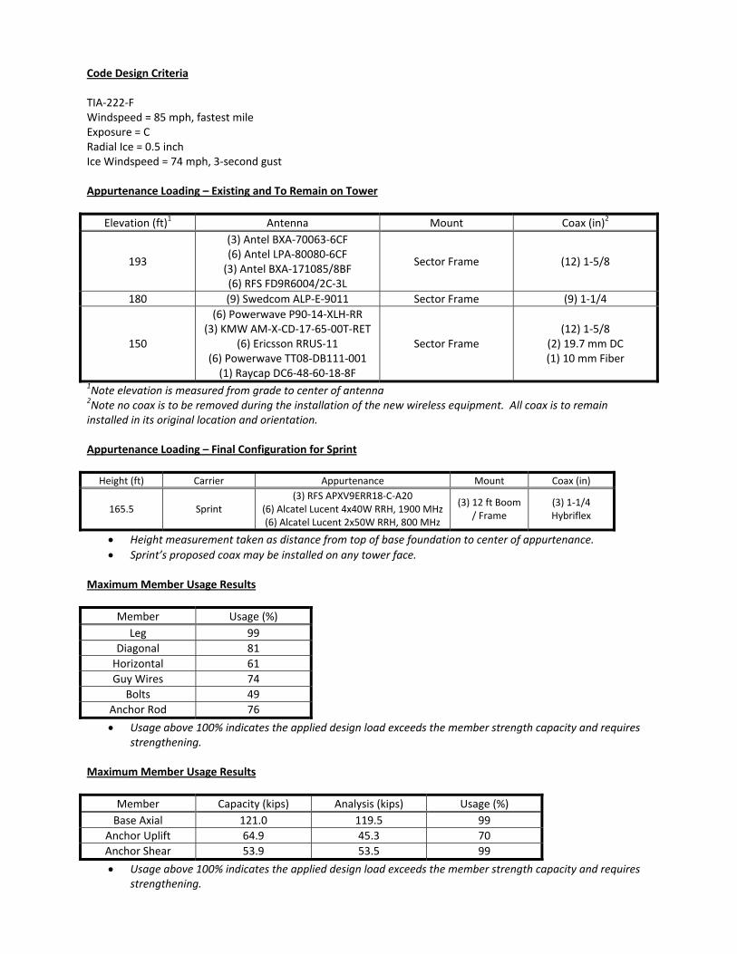
���Code�Design�Criteria��TIAͲ222ͲF�Windspeed�=�85�mph,�fastest�mile�Exposure�=�C�Radial�Ice�=�0.5�inch�Ice�Windspeed�=�74�mph,�3Ͳsecond�gust��Appurtenance�Loading�–�Existing�and�To�Remain�on�Tower��
Elevation�(ft)1� Antenna Mount Coax�(in)2
193�
(3)�Antel�BXAͲ70063Ͳ6CF(6)�Antel�LPAͲ80080Ͳ6CF�(3)�Antel�BXAͲ171085/8BF�(6)�RFS�FD9R6004/2CͲ3L�
Sector�Frame� (12)�1Ͳ5/8�
180� (9)�Swedcom�ALPͲEͲ9011 Sector�Frame (9)�1Ͳ1/4
150�
(6)�Powerwave�P90Ͳ14ͲXLHͲRR(3)�KMW�AMͲXͲCDͲ17Ͳ65Ͳ00TͲRET�
(6)�Ericsson�RRUSͲ11�(6)�Powerwave�TT08ͲDB111Ͳ001�(1)�Raycap�DC6Ͳ48Ͳ60Ͳ18Ͳ8F�
Sector�Frame�(12)�1Ͳ5/8�
(2)�19.7�mm�DC�(1)�10�mm�Fiber�
1Note�elevation�is�measured�from�grade�to�center�of�antenna�2Note�no�coax�is�to�be�removed�during�the�installation�of�the�new�wireless�equipment.��All�coax�is�to�remain�installed�in�its�original�location�and�orientation.��Appurtenance�Loading�–�Final�Configuration�for�Sprint��
Height�(ft)� Carrier� Appurtenance� Mount� Coax�(in)�
165.5� Sprint�(3)�RFS�APXV9ERR18ͲCͲA20�
(6)�Alcatel�Lucent�4x40W�RRH,�1900�MHz�(6)�Alcatel�Lucent�2x50W�RRH,�800�MHz�
(3)�12�ft�Boom�/�Frame
(3)�1Ͳ1/4�Hybriflex�
x Height�measurement�taken�as�distance�from�top�of�base�foundation�to�center�of�appurtenance.�x Sprint’s�proposed�coax�may�be�installed�on�any�tower�face.���
�Maximum�Member�Usage�Results��
Member� Usage�(%)�Leg� 99�
Diagonal� 81�Horizontal� 61�Guy�Wires� 74�
Bolts� 49�Anchor�Rod� 76�x Usage�above�100%�indicates�the�applied�design�load�exceeds�the�member�strength�capacity�and�requires�
strengthening.����Maximum�Member�Usage�Results��
Member� Capacity�(kips)� Analysis�(kips) Usage�(%)Base�Axial� 121.0� 119.5 99
Anchor�Uplift� 64.9� 45.3 70Anchor�Shear� 53.9� 53.5 99x Usage�above�100%�indicates�the�applied�design�load�exceeds�the�member�strength�capacity�and�requires�
strengthening.���
Phone: FAX:
Job: 114-13067 Project: Eastford, CT Client: CDT Drawn by: FAN App'd:
Code: TIA/EIA-222-F Date: 03/29/14 Scale: NTS Path:
C:\Users\Bryan\Documents\Fred Nudd Projects\114-13067 Eastford CT Structural Analysis For Sprint\RISA Files\114-13067 - Eastford CT - Sprint.eri
Dwg No. E-1
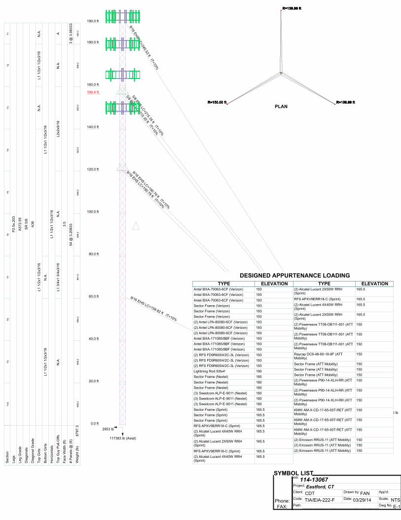
5/8 EHS LC=215.35 ft IT=10%
R=150.00 ft
5/8 EHS LC=215.35 ft IT=10%
9/16 EHS LC=190.79 ft IT=10%
9/16 EHS LC=190.79 ft IT=10%
9/16 EHS LC=159.82 ft IT=10%
9/16 EHS LC=240.53 ft IT=10%
190.0 ft
180.0 ft
160.0 ft
140.0 ft
156.4 ft156.4 ft156.4 ft156.4 ft156.4 ft156.4 ft
120.0 ft
100.0 ft
80.0 ft
60.0 ft
40.0 ft
20.0 ft
0.0 ft
117383 lb (Axial)
2953 lb53544 lb
45285 lb
70126 lb
Sec
tion
T1T2
T3T4
T5T6
T7T8
T9T1
0
Leg
sP
2.5x
.203
Leg
Gra
deA
572-
55
Dia
gona
lsS
R 5
/8
Dia
gona
l Gra
deA
36
Top
Girt
sN
.A.
L1 1
/2x1
1/2
x3/1
6N
.A.
L1 1
/2x1
1/2
x3/1
6
Bot
tom
Girt
sL1
1/2
x1 1
/2x3
/16
N.A
.L1
1/2
x1 1
/2x3
/16
Hor
izon
tals
L1 1
/2x1
1/2
x3/1
6
Top
Guy
Pul
l-Offs
AN
.A.
L2x2
x5/1
6N
.A.
L1 3
/4x1
3/4
x3/1
6N
.A.
Fac
e W
idth
(ft)
3.5
# P
anel
s @
(ft)
3 @
3.0
8333
54 @
3.2
0833
Wei
ght (
lb)
340.
365
8.2
923.
092
3.0
658.
265
8.2
661.
665
8.2
658.
265
8.2
6797
.3
PLANR=150.00 ft R=150.00 ft
R=150.00 ft
R=150.00 ft R=150.00 ft
R=150.00 ft
R=150.00 ft R=150.00 ft
R=150.00 ft
R=150.00 ft R=150.00 ft
R=150.00 ft
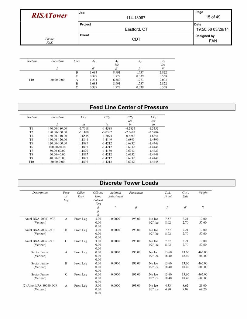
Antel BXA-70063-6CF (Verizon) 193 Antel BXA-70063-6CF (Verizon) 193 Antel BXA-70063-6CF (Verizon) 193 Sector Frame (Verizon) 193 Sector Frame (Verizon) 193 Sector Frame (Verizon) 193 (2) Antel LPA-80080-6CF (Verizon) 193 (2) Antel LPA-80080-6CF (Verizon) 193 (2) Antel LPA-80080-6CF (Verizon) 193 Antel BXA-171085/8BF (Verizon) 193 Antel BXA-171085/8BF (Verizon) 193 Antel BXA-171085/8BF (Verizon) 193 (2) RFS FD9R6004/2C-3L (Verizon) 193 (2) RFS FD9R6004/2C-3L (Verizon) 193 (2) RFS FD9R6004/2C-3L (Verizon) 193 Lightning Rod 5/8x4' 190 Sector Frame (Nextel) 180 Sector Frame (Nextel) 180 Sector Frame (Nextel) 180 (3) Swedcom ALP-E-9011 (Nextel) 180 (3) Swedcom ALP-E-9011 (Nextel) 180 (3) Swedcom ALP-E-9011 (Nextel) 180 Sector Frame (Sprint) 165.5 Sector Frame (Sprint) 165.5 Sector Frame (Sprint) 165.5 RFS APXV9ERR18-C (Sprint) 165.5 (2) Alcatel Lucent 4X40W RRH (Sprint)
165.5 (2) Alcatel Lucent 2X50W RRH (Sprint)
165.5 RFS APXV9ERR18-C (Sprint) 165.5 (2) Alcatel Lucent 4X40W RRH (Sprint)
165.5 (2) Alcatel Lucent 2X50W RRH (Sprint)
165.5 RFS APXV9ERR18-C (Sprint) 165.5 (2) Alcatel Lucent 4X40W RRH (Sprint)
165.5 (2) Alcatel Lucent 2X50W RRH (Sprint)
165.5 (2) Powerwave TT08-DB111-001 (ATT Mobility)
150 (2) Powerwave TT08-DB111-001 (ATT Mobility)
150 (2) Powerwave TT08-DB111-001 (ATT Mobility)
150 Raycap DC6-48-60-18-8F (ATT Mobility)
150 Sector Frame (ATT Mobility) 150 Sector Frame (ATT Mobility) 150 Sector Frame (ATT Mobility) 150 (2) Powerwave P90-14-XLH-RR (ATT Mobility)
150 (2) Powerwave P90-14-XLH-RR (ATT Mobility)
150 (2) Powerwave P90-14-XLH-RR (ATT Mobility)
150 KMW AM-X-CD-17-65-00T-RET (ATT Mobility)
150 KMW AM-X-CD-17-65-00T-RET (ATT Mobility)
150 KMW AM-X-CD-17-65-00T-RET (ATT Mobility)
150 (2) Ericsson RRUS-11 (ATT Mobility) 150 (2) Ericsson RRUS-11 (ATT Mobility) 150 (2) Ericsson RRUS-11 (ATT Mobility) 150DESIGNED APPURTENANCE LOADINGTYPE TYPEELEVATION ELEVATION
Antel BXA-70063-6CF (Verizon) 193 Antel BXA-70063-6CF (Verizon) 193 Antel BXA-70063-6CF (Verizon) 193 Sector Frame (Verizon) 193 Sector Frame (Verizon) 193 Sector Frame (Verizon) 193 (2) Antel LPA-80080-6CF (Verizon) 193 (2) Antel LPA-80080-6CF (Verizon) 193 (2) Antel LPA-80080-6CF (Verizon) 193 Antel BXA-171085/8BF (Verizon) 193 Antel BXA-171085/8BF (Verizon) 193 Antel BXA-171085/8BF (Verizon) 193 (2) RFS FD9R6004/2C-3L (Verizon) 193 (2) RFS FD9R6004/2C-3L (Verizon) 193 (2) RFS FD9R6004/2C-3L (Verizon) 193 Lightning Rod 5/8x4' 190 Sector Frame (Nextel) 180 Sector Frame (Nextel) 180 Sector Frame (Nextel) 180 (3) Swedcom ALP-E-9011 (Nextel) 180 (3) Swedcom ALP-E-9011 (Nextel) 180 (3) Swedcom ALP-E-9011 (Nextel) 180 Sector Frame (Sprint) 165.5 Sector Frame (Sprint) 165.5 Sector Frame (Sprint) 165.5 RFS APXV9ERR18-C (Sprint) 165.5 (2) Alcatel Lucent 4X40W RRH (Sprint)
165.5
(2) Alcatel Lucent 2X50W RRH (Sprint)
165.5
RFS APXV9ERR18-C (Sprint) 165.5 (2) Alcatel Lucent 4X40W RRH (Sprint)
165.5
(2) Alcatel Lucent 2X50W RRH (Sprint)
165.5
RFS APXV9ERR18-C (Sprint) 165.5 (2) Alcatel Lucent 4X40W RRH (Sprint)
165.5
(2) Alcatel Lucent 2X50W RRH (Sprint)
165.5
(2) Powerwave TT08-DB111-001 (ATT Mobility)
150
(2) Powerwave TT08-DB111-001 (ATT Mobility)
150
(2) Powerwave TT08-DB111-001 (ATT Mobility)
150
Raycap DC6-48-60-18-8F (ATT Mobility)
150
Sector Frame (ATT Mobility) 150 Sector Frame (ATT Mobility) 150 Sector Frame (ATT Mobility) 150 (2) Powerwave P90-14-XLH-RR (ATT Mobility)
150
(2) Powerwave P90-14-XLH-RR (ATT Mobility)
150
(2) Powerwave P90-14-XLH-RR (ATT Mobility)
150
KMW AM-X-CD-17-65-00T-RET (ATT Mobility)
150
KMW AM-X-CD-17-65-00T-RET (ATT Mobility)
150
KMW AM-X-CD-17-65-00T-RET (ATT Mobility)
150
(2) Ericsson RRUS-11 (ATT Mobility) 150 (2) Ericsson RRUS-11 (ATT Mobility) 150 (2) Ericsson RRUS-11 (ATT Mobility) 150
SYMBOL LIST
Phone: FAX:
Job: 114-13067 Project: Eastford, CT Client: CDT Drawn by: FAN App'd:
Code: TIA/EIA-222-F Date: 03/29/14 Scale: NTS Path:
C:\Users\Bryan\Documents\Fred Nudd Projects\114-13067 Eastford CT Structural Analysis For Sprint\RISA Files\114-13067 - Eastford CT - Sprint.eri
Dwg No. E-7
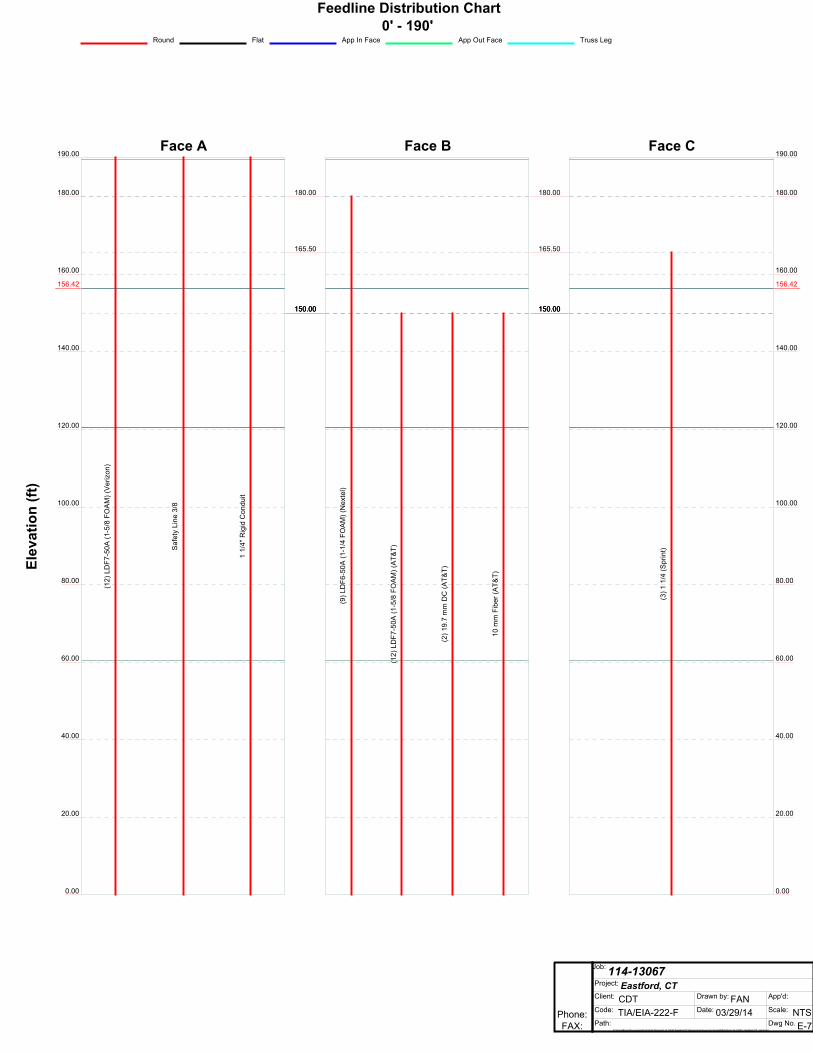
Feedline Distribution Chart0' - 190'
Round Flat App In Face App Out Face Truss Leg
Face A
180.00
160.00
140.00
156.42156.42156.42156.42156.42156.42
120.00
100.00
80.00
60.00
40.00
20.00
0.00
190.00
Elev
atio
n (ft
)
(12)
LD
F7-5
0A (1
-5/8
FO
AM
) (V
eriz
on)
Saf
ety
Line
3/8
1 1/
4" R
igid
Con
duit
Face B
180.00
165.50
150.00150.00150.00
(9) L
DF6
-50A
(1-1
/4 F
OA
M) (
Nex
tel)
(12)
LD
F7-5
0A (1
-5/8
FO
AM
) (A
T&T)
(2) 1
9.7
mm
DC
(AT&
T)
10 m
m F
iber
(AT&
T)
Face C
180.00
160.00
140.00
156.42156.42156.42156.42156.42156.42
120.00
100.00
80.00
60.00
40.00
20.00
0.00
190.00
180.00
165.50
150.00150.00150.00
(3) 1
1/4
(Spr
int)

RRIISSAATToowweerr Job 114-13067
Page 1 of 49
Project Eastford, CT
Date 19:50:58 03/29/14
Phone: FAX:
Client CDT
Designed by FAN
�
Tower Input Data The main tower is a 3x guyed tower with an overall height of 190.00 ft above the ground line. The base of the tower is set at an elevation of 0.00 ft above the ground line. The face width of the tower is 3.50 ft at the top and 3.50 ft at the base. This tower is designed using the TIA/EIA-222-F standard. The following design criteria apply:
Tower is located in New London County, Connecticut. Basic wind speed of 85 mph. Nominal ice thickness of 0.5000 in. Ice density of 56 pcf. A wind speed of 74 mph is used in combination with ice. Temperature drop of 50 °F. Deflections calculated using a wind speed of 50 mph. Weld together tower sections have flange connections.. Tension only take-up is 0.0313 in. Pressures are calculated at each section. Safety factor used in guy design is 2. Stress ratio used in tower member design is 1.333. Local bending stresses due to climbing loads, feedline supports, and appurtenance mounts are not considered.
Options
Consider Moments - Legs Distribute Leg Loads As Uniform Treat Feedline Bundles As Cylinder Consider Moments - Horizontals Assume Legs Pinned Use ASCE 10 X-Brace Ly Rules Consider Moments - Diagonals ¥ Assume Rigid Index Plate ¥ Calculate Redundant Bracing Forces Use Moment Magnification ¥ Use Clear Spans For Wind Area Ignore Redundant Members in FEA ¥ Use Code Stress Ratios ¥ Use Clear Spans For KL/r SR Leg Bolts Resist Compression ¥ Use Code Safety Factors - Guys ¥ Retension Guys To Initial Tension ¥ All Leg Panels Have Same Allowable Escalate Ice Bypass Mast Stability Checks Offset Girt At Foundation Always Use Max Kz ¥ Use Azimuth Dish Coefficients ¥ Consider Feedline Torque Use Special Wind Profile ¥ Project Wind Area of Appurt. Include Angle Block Shear Check ¥ Include Bolts In Member Capacity ¥ Autocalc Torque Arm Areas Poles ¥ Leg Bolts Are At Top Of Section SR Members Have Cut Ends Include Shear-Torsion Interaction ¥ Secondary Horizontal Braces Leg Sort Capacity Reports By Component Always Use Sub-Critical Flow Use Diamond Inner Bracing (4 Sided) ¥ Triangulate Diamond Inner Bracing Use Top Mounted Sockets Add IBC .6D+W Combination
RRIISSAATToowweerr Job 114-13067
Page 2 of 49
Project Eastford, CT
Date 19:50:58 03/29/14
Phone: FAX:
Client CDT
Designed by FAN
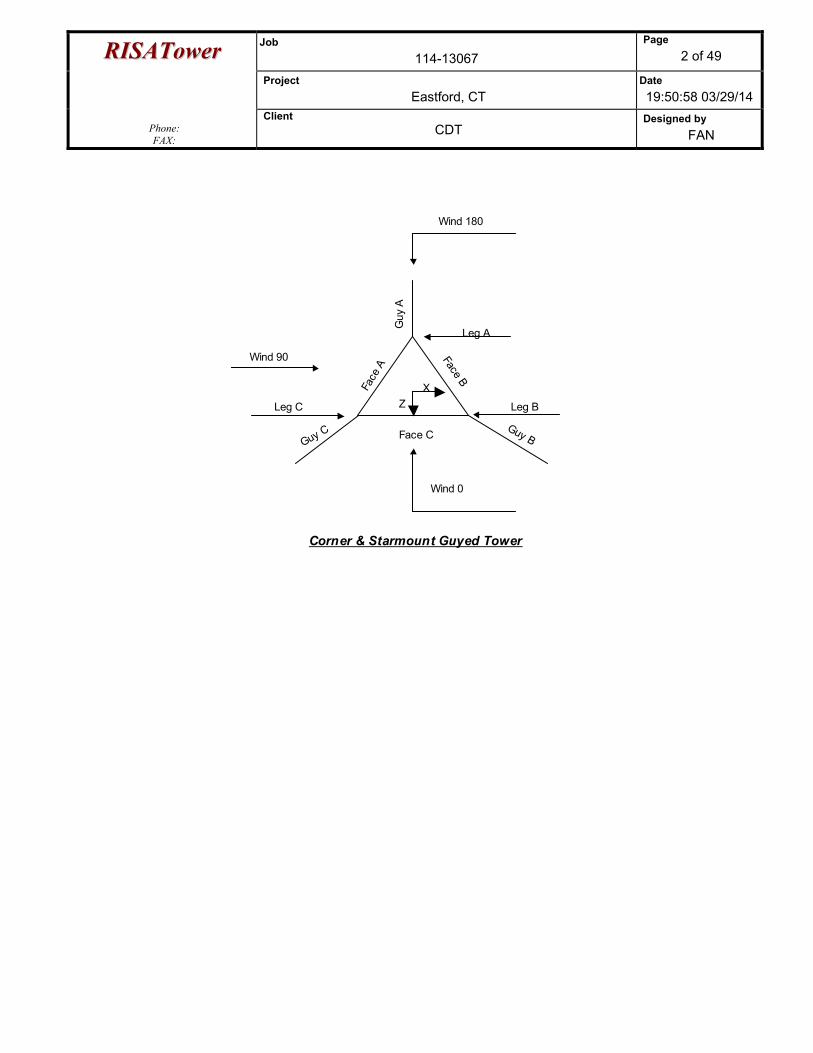
Leg B
Guy B
Leg C
Guy C
Leg A
Guy
A
Face
A Face B
Face C
Corner & Starmount Guyed Tower
Wind 0
Wind 90
Wind 180
Z X
RRIISSAATToowweerr Job 114-13067
Page 3 of 49
Project Eastford, CT
Date 19:50:58 03/29/14
Phone: FAX:
Client CDT
Designed by FAN
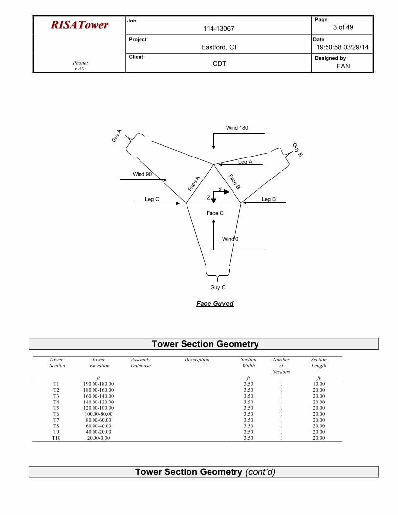
Leg B
Guy B
Leg C
Guy C
Leg A
Guy A
Face
A Face B
Face C
Face Guyed
Wind 0
Wind 90
Wind 180
Z
X
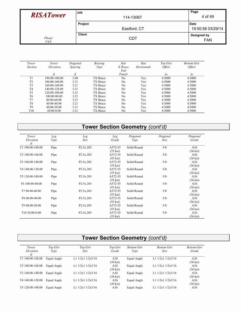
Tower Section Geometry
Tower Section
Tower Elevation
ft
Assembly Database
Description Section Width
ft
Number of
Sections
Section Length
ft
T1 190.00-180.00 3.50 1 10.00 T2 180.00-160.00 3.50 1 20.00 T3 160.00-140.00 3.50 1 20.00 T4 140.00-120.00 3.50 1 20.00 T5 120.00-100.00 3.50 1 20.00 T6 100.00-80.00 3.50 1 20.00 T7 80.00-60.00 3.50 1 20.00 T8 60.00-40.00 3.50 1 20.00 T9 40.00-20.00 3.50 1 20.00
T10 20.00-0.00 3.50 1 20.00
Tower Section Geometry (cont’d)
RRIISSAATToowweerr Job 114-13067
Page 4 of 49
Project Eastford, CT
Date 19:50:58 03/29/14
Phone: FAX:
Client CDT
Designed by FAN
Tower
Section Tower
Elevation
ft
Diagonal Spacing
ft
Bracing Type
Has K Brace
End Panels
Has Horizontals
Top Girt Offset
in
Bottom Girt Offset
in
T1 190.00-180.00 3.08 TX Brace No Yes 4.5000 4.5000 T2 180.00-160.00 3.21 TX Brace No Yes 4.5000 4.5000 T3 160.00-140.00 3.21 TX Brace No Yes 4.5000 4.5000 T4 140.00-120.00 3.21 TX Brace No Yes 4.5000 4.5000 T5 120.00-100.00 3.21 TX Brace No Yes 4.5000 4.5000 T6 100.00-80.00 3.21 TX Brace No Yes 4.5000 4.5000 T7 80.00-60.00 3.21 TX Brace No Yes 4.5000 4.5000 T8 60.00-40.00 3.21 TX Brace No Yes 4.5000 4.5000 T9 40.00-20.00 3.21 TX Brace No Yes 4.5000 4.5000
T10 20.00-0.00 3.21 TX Brace No Yes 4.5000 4.5000
Tower Section Geometry (cont’d)
Tower Elevation
ft
Leg Type
Leg Size
Leg Grade
Diagonal Type
Diagonal Size
Diagonal Grade
T1 190.00-180.00 Pipe P2.5x.203 A572-55 (55 ksi)
Solid Round 5/8 A36 (36 ksi)
T2 180.00-160.00 Pipe P2.5x.203 A572-55 (55 ksi)
Solid Round 5/8 A36 (36 ksi)
T3 160.00-140.00 Pipe P2.5x.203 A572-55 (55 ksi)
Solid Round 5/8 A36 (36 ksi)
T4 140.00-120.00 Pipe P2.5x.203 A572-55 (55 ksi)
Solid Round 5/8 A36 (36 ksi)
T5 120.00-100.00 Pipe P2.5x.203 A572-55 (55 ksi)
Solid Round 5/8 A36 (36 ksi)
T6 100.00-80.00 Pipe P2.5x.203 A572-55 (55 ksi)
Solid Round 5/8 A36 (36 ksi)
T7 80.00-60.00 Pipe P2.5x.203 A572-55 (55 ksi)
Solid Round 5/8 A36 (36 ksi)
T8 60.00-40.00 Pipe P2.5x.203 A572-55 (55 ksi)
Solid Round 5/8 A36 (36 ksi)
T9 40.00-20.00 Pipe P2.5x.203 A572-55 (55 ksi)
Solid Round 5/8 A36 (36 ksi)
T10 20.00-0.00 Pipe P2.5x.203 A572-55 (55 ksi)
Solid Round 5/8 A36 (36 ksi)
Tower Section Geometry (cont’d)
Tower Elevation
ft
Top Girt Type
Top Girt Size
Top Girt Grade
Bottom Girt Type
Bottom Girt Size
Bottom Girt Grade
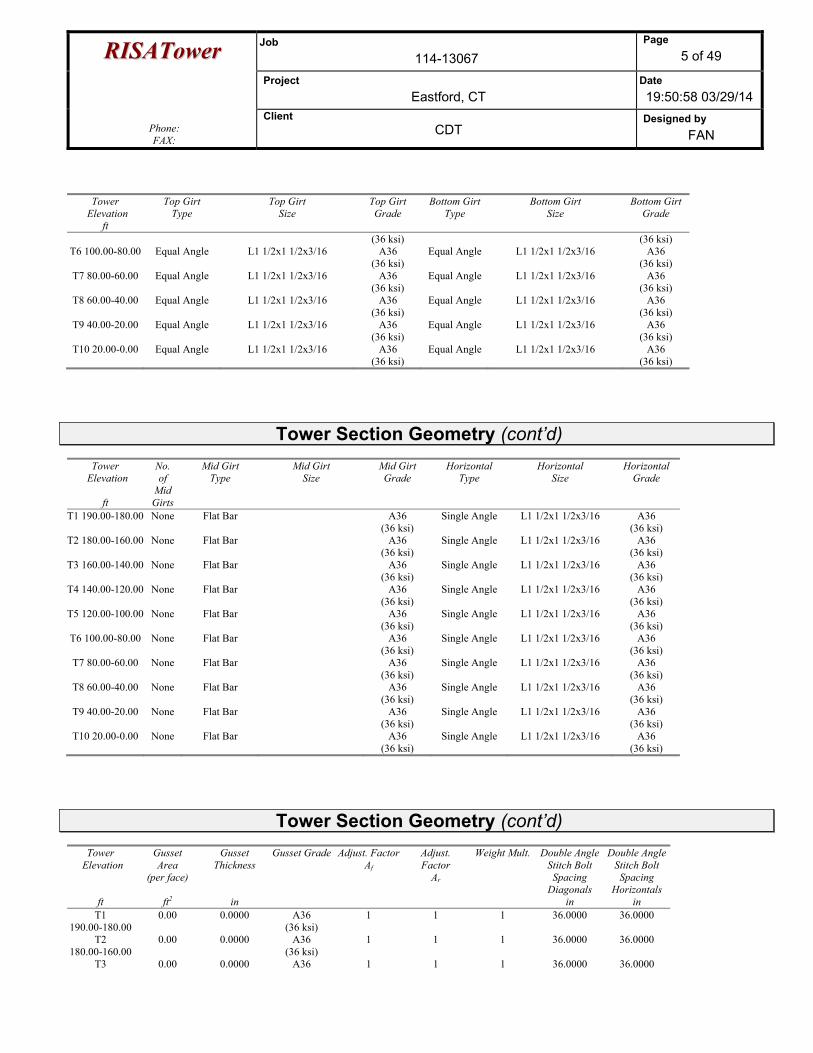
T1 190.00-180.00 Equal Angle L1 1/2x1 1/2x3/16 A36 (36 ksi)
Equal Angle L1 1/2x1 1/2x3/16 A36 (36 ksi)
T2 180.00-160.00 Equal Angle L1 1/2x1 1/2x3/16 A36 (36 ksi)
Equal Angle L1 1/2x1 1/2x3/16 A36 (36 ksi)
T3 160.00-140.00 Equal Angle L1 1/2x1 1/2x3/16 A36 (36 ksi)
Equal Angle L1 1/2x1 1/2x3/16 A36 (36 ksi)
T4 140.00-120.00 Equal Angle L1 1/2x1 1/2x3/16 A36 (36 ksi)
Equal Angle L1 1/2x1 1/2x3/16 A36 (36 ksi)
T5 120.00-100.00 Equal Angle L1 1/2x1 1/2x3/16 A36 Equal Angle L1 1/2x1 1/2x3/16 A36
RRIISSAATToowweerr Job 114-13067
Page 5 of 49
Project Eastford, CT
Date 19:50:58 03/29/14
Phone: FAX:
Client CDT
Designed by FAN
Tower Elevation
ft
Top Girt Type
Top Girt Size
Top Girt Grade
Bottom Girt Type
Bottom Girt Size
Bottom Girt Grade
(36 ksi) (36 ksi) T6 100.00-80.00 Equal Angle L1 1/2x1 1/2x3/16 A36
(36 ksi) Equal Angle L1 1/2x1 1/2x3/16 A36
(36 ksi) T7 80.00-60.00 Equal Angle L1 1/2x1 1/2x3/16 A36
(36 ksi) Equal Angle L1 1/2x1 1/2x3/16 A36
(36 ksi) T8 60.00-40.00 Equal Angle L1 1/2x1 1/2x3/16 A36
(36 ksi) Equal Angle L1 1/2x1 1/2x3/16 A36
(36 ksi) T9 40.00-20.00 Equal Angle L1 1/2x1 1/2x3/16 A36
(36 ksi) Equal Angle L1 1/2x1 1/2x3/16 A36
(36 ksi) T10 20.00-0.00 Equal Angle L1 1/2x1 1/2x3/16 A36
(36 ksi) Equal Angle L1 1/2x1 1/2x3/16 A36
(36 ksi)
Tower Section Geometry (cont’d)
Tower Elevation
ft
No. of
Mid Girts
Mid Girt Type
Mid Girt Size
Mid Girt Grade
Horizontal Type
Horizontal Size
Horizontal Grade
T1 190.00-180.00 None Flat Bar A36 (36 ksi)
Single Angle L1 1/2x1 1/2x3/16 A36 (36 ksi)
T2 180.00-160.00 None Flat Bar A36 (36 ksi)
Single Angle L1 1/2x1 1/2x3/16 A36 (36 ksi)
T3 160.00-140.00 None Flat Bar A36 (36 ksi)
Single Angle L1 1/2x1 1/2x3/16 A36 (36 ksi)
T4 140.00-120.00 None Flat Bar A36 (36 ksi)
Single Angle L1 1/2x1 1/2x3/16 A36 (36 ksi)
T5 120.00-100.00 None Flat Bar A36 (36 ksi)
Single Angle L1 1/2x1 1/2x3/16 A36 (36 ksi)
T6 100.00-80.00 None Flat Bar A36 (36 ksi)
Single Angle L1 1/2x1 1/2x3/16 A36 (36 ksi)
T7 80.00-60.00 None Flat Bar A36 (36 ksi)
Single Angle L1 1/2x1 1/2x3/16 A36 (36 ksi)
T8 60.00-40.00 None Flat Bar A36 (36 ksi)
Single Angle L1 1/2x1 1/2x3/16 A36 (36 ksi)
T9 40.00-20.00 None Flat Bar A36 (36 ksi)
Single Angle L1 1/2x1 1/2x3/16 A36 (36 ksi)
T10 20.00-0.00 None Flat Bar A36 (36 ksi)
Single Angle L1 1/2x1 1/2x3/16 A36 (36 ksi)
Tower Section Geometry (cont’d)
Tower Elevation
ft
Gusset Area
(per face)
ft2
Gusset Thickness
in
Gusset Grade Adjust. FactorAf
Adjust. Factor
Ar
Weight Mult.
Double Angle Stitch Bolt Spacing
Diagonals in
Double Angle Stitch Bolt Spacing
Horizontals in
T1 190.00-180.00
0.00 0.0000 A36 (36 ksi)
1 1 1 36.0000 36.0000
T2 180.00-160.00
0.00 0.0000 A36 (36 ksi)
1 1 1 36.0000 36.0000
T3 0.00 0.0000 A36 1 1 1 36.0000 36.0000
RRIISSAATToowweerr Job 114-13067
Page 6 of 49
Project Eastford, CT
Date 19:50:58 03/29/14
Phone: FAX:
Client CDT
Designed by FAN
Tower Elevation
ft
Gusset Area
(per face)
ft2
Gusset Thickness
in
Gusset Grade Adjust. FactorAf
Adjust. Factor
Ar
Weight Mult.
Double Angle Stitch Bolt Spacing
Diagonals in
Double Angle Stitch Bolt Spacing
Horizontals in
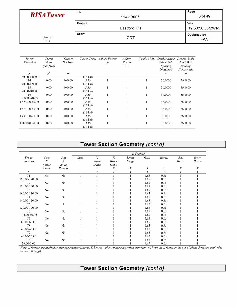
160.00-140.00 (36 ksi) T4
140.00-120.00 0.00 0.0000 A36
(36 ksi) 1 1 1 36.0000 36.0000
T5 120.00-100.00
0.00 0.0000 A36 (36 ksi)
1 1 1 36.0000 36.0000
T6 100.00-80.00
0.00 0.0000 A36 (36 ksi)
1 1 1 36.0000 36.0000
T7 80.00-60.00 0.00 0.0000 A36 (36 ksi)
1 1 1 36.0000 36.0000
T8 60.00-40.00 0.00 0.0000 A36 (36 ksi)
1 1 1 36.0000 36.0000
T9 40.00-20.00 0.00 0.0000 A36 (36 ksi)
1 1 1 36.0000 36.0000
T10 20.00-0.00 0.00 0.0000 A36 (36 ksi)
1 1 1 36.0000 36.0000
Tower Section Geometry (cont’d)
K Factors1
Tower Elevation
ft
Calc K
Single Angles
Calc K
Solid Rounds
Legs X Brace Diags
X Y
K Brace Diags
X Y
Single Diags
X Y
Girts
X Y
Horiz.
X Y
Sec. Horiz.
X Y
Inner Brace
X Y
T1 190.00-180.00
No No 1 1 1
1 1
1 1
0.65 0.65
0.65 0.65
1 1
1 1
T2 180.00-160.00
No No 1 1 1
1 1
1 1
0.65 0.65
0.65 0.65
1 1
1 1
T3 160.00-140.00
No No 1 1 1
1 1
1 1
0.65 0.65
0.65 0.65
1 1
1 1
T4 140.00-120.00
No No 1 1 1
1 1
1 1
0.65 0.65
0.65 0.65
1 1
1 1
T5 120.00-100.00
No No 1 1 1
1 1
1 1
0.65 0.65
0.65 0.65
1 1
1 1
T6 100.00-80.00
No No 1 1 1
1 1
1 1
0.65 0.65
0.65 0.65
1 1
1 1
T7 80.00-60.00
No No 1 1 1
1 1
1 1
0.65 0.65
0.65 0.65
1 1
1 1
T8 60.00-40.00
No No 1 1 1
1 1
1 1
0.65 0.65
0.65 0.65
1 1
1 1
T9 40.00-20.00
No No 1 1 1
1 1
1 1
0.65 0.65
0.65 0.65
1 1
1 1
T10 20.00-0.00
No No 1 1 1
1 1
1 1
0.65 0.65
0.65 0.65
1 1
1 1
1Note: K factors are applied to member segment lengths. K-braces without inner supporting members will have the K factor in the out-of-plane direction applied to the overall length.
Tower Section Geometry (cont’d)
RRIISSAATToowweerr Job 114-13067
Page 7 of 49
Project Eastford, CT
Date 19:50:58 03/29/14
Phone: FAX:
Client CDT
Designed by FAN
Tower Elevation
ft
Leg Diagonal Top Girt Bottom Girt Mid Girt Long Horizontal Short Horizontal
Net Width Deduct
in
U
Net Width Deduct
in
U
Net WidthDeduct
in
U
Net Width
Deduct in
U
Net Width
Deduct in
U
Net Width
Deduct in
U
Net Width
Deduct in
U
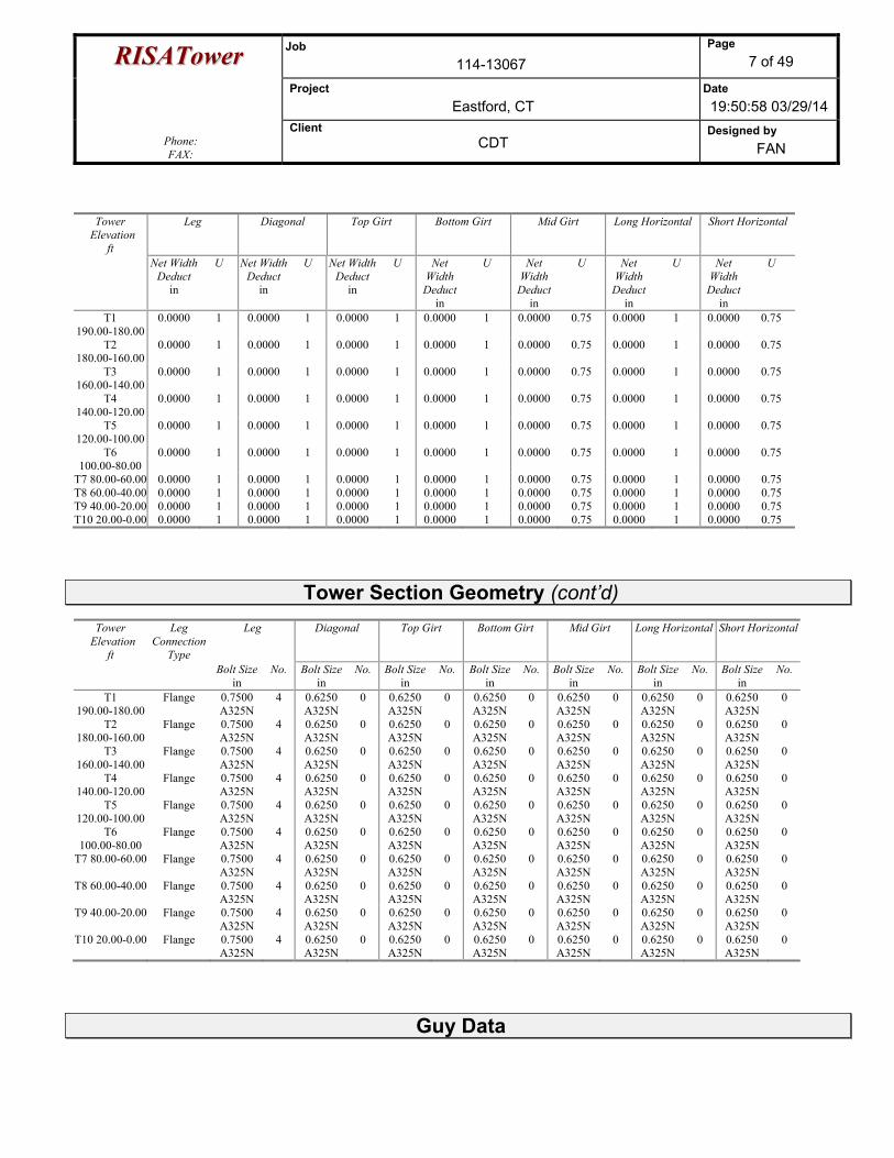
T1 190.00-180.00
0.0000 1 0.0000 1 0.0000 1 0.0000 1 0.0000 0.75 0.0000 1 0.0000 0.75
T2 180.00-160.00
0.0000 1 0.0000 1 0.0000 1 0.0000 1 0.0000 0.75 0.0000 1 0.0000 0.75
T3 160.00-140.00
0.0000 1 0.0000 1 0.0000 1 0.0000 1 0.0000 0.75 0.0000 1 0.0000 0.75
T4 140.00-120.00
0.0000 1 0.0000 1 0.0000 1 0.0000 1 0.0000 0.75 0.0000 1 0.0000 0.75
T5 120.00-100.00
0.0000 1 0.0000 1 0.0000 1 0.0000 1 0.0000 0.75 0.0000 1 0.0000 0.75
T6 100.00-80.00
0.0000 1 0.0000 1 0.0000 1 0.0000 1 0.0000 0.75 0.0000 1 0.0000 0.75
T7 80.00-60.00 0.0000 1 0.0000 1 0.0000 1 0.0000 1 0.0000 0.75 0.0000 1 0.0000 0.75 T8 60.00-40.00 0.0000 1 0.0000 1 0.0000 1 0.0000 1 0.0000 0.75 0.0000 1 0.0000 0.75 T9 40.00-20.00 0.0000 1 0.0000 1 0.0000 1 0.0000 1 0.0000 0.75 0.0000 1 0.0000 0.75 T10 20.00-0.00 0.0000 1 0.0000 1 0.0000 1 0.0000 1 0.0000 0.75 0.0000 1 0.0000 0.75
Tower Section Geometry (cont’d)
Tower Elevation
ft
Leg Connection
Type
Leg Diagonal Top Girt Bottom Girt Mid Girt Long Horizontal Short Horizontal
Bolt Size in
No. Bolt Size in
No. Bolt Sizein
No. Bolt Sizein
No. Bolt Sizein
No. Bolt Size in
No. Bolt Sizein
No.
T1 190.00-180.00
Flange 0.7500 A325N
4 0.6250 A325N
0 0.6250 A325N
0 0.6250 A325N
0 0.6250 A325N
0 0.6250 A325N
0 0.6250 A325N
0
T2 180.00-160.00
Flange 0.7500 A325N
4 0.6250 A325N
0 0.6250 A325N
0 0.6250 A325N
0 0.6250 A325N
0 0.6250 A325N
0 0.6250 A325N
0
T3 160.00-140.00
Flange 0.7500 A325N
4 0.6250 A325N
0 0.6250 A325N
0 0.6250 A325N
0 0.6250 A325N
0 0.6250 A325N
0 0.6250 A325N
0
T4 140.00-120.00
Flange 0.7500 A325N
4 0.6250 A325N
0 0.6250 A325N
0 0.6250 A325N
0 0.6250 A325N
0 0.6250 A325N
0 0.6250 A325N
0
T5 120.00-100.00
Flange 0.7500 A325N
4 0.6250 A325N
0 0.6250 A325N
0 0.6250 A325N
0 0.6250 A325N
0 0.6250 A325N
0 0.6250 A325N
0
T6 100.00-80.00
Flange 0.7500 A325N
4 0.6250 A325N
0 0.6250 A325N
0 0.6250 A325N
0 0.6250 A325N
0 0.6250 A325N
0 0.6250 A325N
0
T7 80.00-60.00 Flange 0.7500 A325N
4 0.6250 A325N
0 0.6250 A325N
0 0.6250 A325N
0 0.6250 A325N
0 0.6250 A325N
0 0.6250 A325N
0
T8 60.00-40.00 Flange 0.7500 A325N
4 0.6250 A325N
0 0.6250 A325N
0 0.6250 A325N
0 0.6250 A325N
0 0.6250 A325N
0 0.6250 A325N
0
T9 40.00-20.00 Flange 0.7500 A325N
4 0.6250 A325N
0 0.6250 A325N
0 0.6250 A325N
0 0.6250 A325N
0 0.6250 A325N
0 0.6250 A325N
0
T10 20.00-0.00 Flange 0.7500 A325N
4 0.6250 A325N
0 0.6250 A325N
0 0.6250 A325N
0 0.6250 A325N
0 0.6250 A325N
0 0.6250 A325N
0
Guy Data

RRIISSAATToowweerr Job 114-13067
Page 8 of 49
Project Eastford, CT
Date 19:50:58 03/29/14
Phone: FAX:
Client CDT
Designed by FAN
Guy Elevation
ft
Guy Grade
Guy Size
Initial Tension
lb
%
Guy Modulus
ksi
Guy Weight
plf
Lu
ft
Anchor Radius
ft
Anchor Azimuth
Adj. °
Anchor Elevation
ft
End Fitting
Efficiency%
156.417 EHS A B C
5/8 5/8 5/8
4240.00 4240.00 4240.00
10%10%10%
21000 21000 21000
0.813 0.813 0.813
215.17 215.17 215.17
150.00 150.00 150.00
0.0000 0.0000 0.0000
0.00 0.00 0.00
100% 100% 100%
120.375 EHS A B C
9/16 9/16 9/16
3500.00 3500.00 3500.00
10%10%10%
21000 21000 21000
0.671 0.671 0.671
190.63 190.63 190.63
150.00 150.00 150.00
0.0000 0.0000 0.0000
0.00 0.00 0.00
100% 100% 100%
60.375 EHS A B C
9/16 9/16 9/16
3500.00 3500.00 3500.00
10%10%10%
21000 21000 21000
0.671 0.671 0.671
159.69 159.69 159.69
150.00 150.00 150.00
0.0000 0.0000 0.0000
0.00 0.00 0.00
100% 100% 100%
189.625 EHS A B C
9/16 9/16 9/16
3500.00 3500.00 3500.00
10%10%10%
21000 21000 21000
0.671 0.671 0.671
240.33 240.33 240.33
150.00 150.00 150.00
0.0000 0.0000 0.0000
0.00 0.00 0.00
100% 100% 100%
Guy Data(cont’d)
Guy Elevation
ft
Mount Type
Torque-Arm Spread
ft
Torque-Arm Leg Angle
°
Torque-Arm Style
Torque-Arm Grade
Torque-Arm Type
Torque-Arm Size
156.417 Torque Arm 7.00 30.0000 Dog Ear A36 (36 ksi)
Single Angle L3x3x1/4
120.375 Torque Arm 7.00 30.0000 Dog Ear A36 (36 ksi)
Single Angle L3x3x1/4
60.375 Corner 189.625 Corner
Guy Data (cont’d)
Guy Elevation
ft
Diagonal Grade
Diagonal Type
Upper Diagonal Size
Lower Diagonal Size
Is Strap.
Pull-Off Grade
Pull-Off Type Pull-Off Size
156.42 A572-50 (50 ksi)
Solid Round No A36 (36 ksi)
Equal Angle L2x2x5/16
120.38 A572-50 (50 ksi)
Solid Round No A36 (36 ksi)
Equal Angle L2x2x5/16
60.38 A572-50 (50 ksi)
Solid Round No A36 (36 ksi)
Equal Angle L1 3/4x1 3/4x3/16
189.63 A572-50 (50 ksi)
Solid Round No A36 (36 ksi)
Equal Angle L1 3/4x1 3/4x3/16
Guy Data (cont’d)
Guy Elevation
ft
Cable Weight
A lb
Cable Weight
B lb
Cable Weight
C lb
Cable Weight
D lb
Tower Intercept
A ft
Tower Intercept
B ft
Tower Intercept
C ft
Tower Intercept
D ft
RRIISSAATToowweerr Job 114-13067
Page 9 of 49
Project Eastford, CT
Date 19:50:58 03/29/14
Phone: FAX:
Client CDT
Designed by FAN
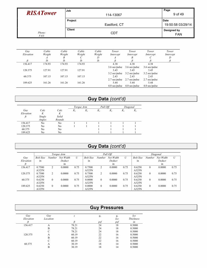
Guy Elevation
ft
Cable Weight
A lb
Cable Weight
B lb
Cable Weight
C lb
Cable Weight
D lb
Tower Intercept
A ft
Tower Intercept
B ft
Tower Intercept
C ft
Tower Intercept
D ft
156.417 174.93 174.93 174.93 4.38 3.6 sec/pulse
4.38 3.6 sec/pulse
4.38 3.6 sec/pulse
120.375 127.91 127.91 127.91 3.45 3.2 sec/pulse
3.45 3.2 sec/pulse
3.45 3.2 sec/pulse
60.375 107.15 107.15 107.15 2.43 2.7 sec/pulse
2.43 2.7 sec/pulse
2.43 2.7 sec/pulse
189.625 161.26 161.26 161.26 5.44 4.0 sec/pulse
5.44 4.0 sec/pulse
5.44 4.0 sec/pulse
Guy Data (cont’d)
Torque Arm Pull Off DiagonalGuy
Elevation ft
Calc K
Single Angles
Calc K
Solid Rounds
Kx Ky Kx Ky Kx Ky
156.417 No No 1 1 1 1 1 1 120.375 No No 1 1 1 1 1 1 60.375 No No 1 1 1 1 189.625 No No 1 1 1 1
Guy Data (cont’d)
Torque-Arm Pull Off Diagonal Guy
Elevation ft
Bolt Size in
Number Net Width Deduct
in
U
Bolt Sizein
Number Net WidthDeduct
in
U
Bolt Sizein
Number Net WidthDeduct
in
U
156.417 0.7500 A325N
2 0.0000 0.75 0.7500 A325N
2 0.0000 0.75 0.6250 A325N
0 0.0000 0.75
120.375 0.7500 A325N
2 0.0000 0.75 0.7500 A325N
2 0.0000 0.75 0.6250 A325N
0 0.0000 0.75
60.375 0.6250 A325N
0 0.0000 0.75 0.0000 A325N
0 0.0000 0.75 0.6250 A325N
0 0.0000 0.75
189.625 0.6250 A325N
0 0.0000 0.75 0.0000 A325N
0 0.0000 0.75 0.6250 A325N
0 0.0000 0.75
Guy Pressures
Guy Elevation
ft
Guy Location
z
ft
qz
psf
qz Ice psf
Ice Thickness
in 156.417 A
B C
78.21 78.21 78.21
24 24 24
18 18 18
0.5000 0.5000 0.5000
120.375 A B C
60.19 60.19 60.19
22 22 22
16 16 16
0.5000 0.5000 0.5000
60.375 A B
30.19 30.19
18 18
14 14
0.5000 0.5000
RRIISSAATToowweerr Job 114-13067
Page 10 of 49
Project Eastford, CT
Date 19:50:58 03/29/14
Phone: FAX:
Client CDT
Designed by FAN
Guy Elevation
ft
Guy Location
z
ft
qz
psf
qz Ice psf
Ice Thickness
in C 30.19 18 14 0.5000
189.625 A B C
94.81 94.81 94.81
25 25 25
19 19 19
0.5000 0.5000 0.5000
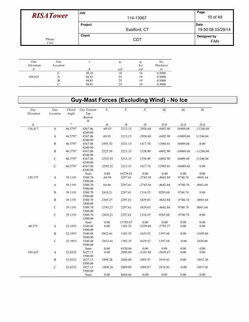
Guy-Mast Forces (Excluding Wind) - No Ice
Guy Elevation
ft
Guy Location
Chord Angle
°
Guy Tension Top
Bottom lb
Fx
lb
Fy
lb
Fz
lb
Mx
lb-ft
My
lb-ft
Mz
lb-ft 156.417 A 46.5797 4367.06
4240.00 -69.93 3213.15 -2956.68 -6492.90 10489.68 -11246.04
A 46.5797 4367.06 4240.00
69.93 3213.15 -2956.68 -6492.90 -10489.68 11246.04
B 46.5797 4367.06 4240.00
2595.52 3213.15 1417.78 12985.81 10489.68 0.00
B 46.5797 4367.06 4240.00
2525.59 3213.15 1538.90 -6492.90 -10489.68 -11246.04
C 46.5797 4367.06 4240.00
-2525.59 3213.15 1538.90 -6492.90 10489.68 11246.04
C 46.5797 4367.06 4240.00
-2595.52 3213.15 1417.78 12985.81 -10489.68 0.00
Sum: 0.00 19278.93 0.00 -0.00 0.00 0.00 120.375 A 39.1191 3580.70
3500.00 -64.94 2297.61 -2745.58 -4642.84 9740.74 -8041.64
A 39.1191 3580.70 3500.00
64.94 2297.61 -2745.58 -4642.84 -9740.74 8041.64
B 39.1191 3580.70 3500.00
2410.21 2297.61 1316.55 9285.68 9740.74 0.00
B 39.1191 3580.70 3500.00
2345.27 2297.61 1429.03 -4642.84 -9740.74 -8041.64
C 39.1191 3580.70 3500.00
-2345.27 2297.61 1429.03 -4642.84 9740.74 8041.64
C 39.1191 3580.70 3500.00
-2410.21 2297.61 1316.55 9285.68 -9740.74 0.00
Sum: 0.00 13785.67 0.00 -0.00 0.00 0.00 60.375 A 22.1953 3540.48
3500.00 0.00 1383.35 -3259.04 -2795.37 0.00 0.00
B 22.1953 3540.48 3500.00
2822.41 1383.35 1629.52 1397.68 0.00 -2420.86
C 22.1953 3540.48 3500.00
-2822.41 1383.35 1629.52 1397.68 -0.00 2420.86
Sum: 0.00 4150.04 0.00 0.00 0.00 0.00 189.625 A 52.0323 3627.13
3500.00 0.00 2889.89 -2191.94 -5839.67 0.00 0.00
B 52.0323 3627.13 3500.00
1898.28 2889.89 1095.97 2919.83 0.00 -5057.30
C 52.0323 3627.13 3500.00
-1898.28 2889.89 1095.97 2919.83 -0.00 5057.30
Sum: 0.00 8669.66 -0.00 0.00 0.00 0.00
RRIISSAATToowweerr Job 114-13067
Page 11 of 49
Project Eastford, CT
Date 19:50:58 03/29/14
Phone: FAX:
Client CDT
Designed by FAN
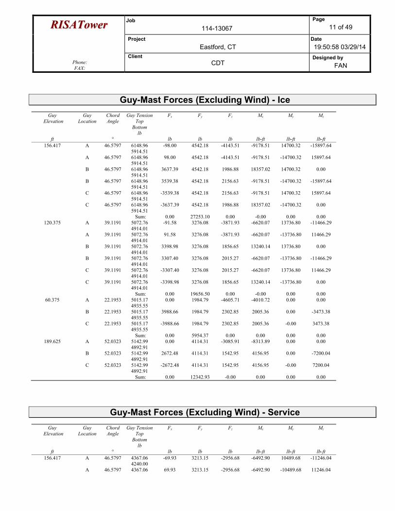
Guy-Mast Forces (Excluding Wind) - Ice
Guy Elevation
ft
Guy Location
Chord Angle
°
Guy Tension Top
Bottom lb
Fx
lb
Fy
lb
Fz
lb
Mx
lb-ft
My
lb-ft
Mz
lb-ft 156.417 A 46.5797 6148.96
5914.51 -98.00 4542.18 -4143.51 -9178.51 14700.32 -15897.64
A 46.5797 6148.96 5914.51
98.00 4542.18 -4143.51 -9178.51 -14700.32 15897.64
B 46.5797 6148.96 5914.51
3637.39 4542.18 1986.88 18357.02 14700.32 0.00
B 46.5797 6148.96 5914.51
3539.38 4542.18 2156.63 -9178.51 -14700.32 -15897.64
C 46.5797 6148.96 5914.51
-3539.38 4542.18 2156.63 -9178.51 14700.32 15897.64
C 46.5797 6148.96 5914.51
-3637.39 4542.18 1986.88 18357.02 -14700.32 0.00
Sum: 0.00 27253.10 0.00 -0.00 0.00 0.00 120.375 A 39.1191 5072.76
4914.01 -91.58 3276.08 -3871.93 -6620.07 13736.80 -11466.29
A 39.1191 5072.76 4914.01
91.58 3276.08 -3871.93 -6620.07 -13736.80 11466.29
B 39.1191 5072.76 4914.01
3398.98 3276.08 1856.65 13240.14 13736.80 0.00
B 39.1191 5072.76 4914.01
3307.40 3276.08 2015.27 -6620.07 -13736.80 -11466.29
C 39.1191 5072.76 4914.01
-3307.40 3276.08 2015.27 -6620.07 13736.80 11466.29
C 39.1191 5072.76 4914.01
-3398.98 3276.08 1856.65 13240.14 -13736.80 0.00
Sum: 0.00 19656.50 0.00 -0.00 0.00 0.00 60.375 A 22.1953 5015.17
4935.55 0.00 1984.79 -4605.71 -4010.72 0.00 0.00
B 22.1953 5015.17 4935.55
3988.66 1984.79 2302.85 2005.36 0.00 -3473.38
C 22.1953 5015.17 4935.55
-3988.66 1984.79 2302.85 2005.36 -0.00 3473.38
Sum: 0.00 5954.37 0.00 0.00 0.00 0.00 189.625 A 52.0323 5142.99
4892.91 0.00 4114.31 -3085.91 -8313.89 0.00 0.00
B 52.0323 5142.99 4892.91
2672.48 4114.31 1542.95 4156.95 0.00 -7200.04
C 52.0323 5142.99 4892.91
-2672.48 4114.31 1542.95 4156.95 -0.00 7200.04
Sum: 0.00 12342.93 -0.00 0.00 0.00 0.00
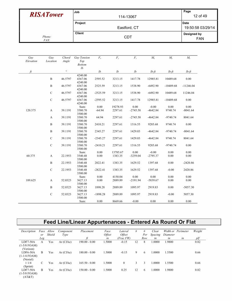
Guy-Mast Forces (Excluding Wind) - Service
Guy Elevation
ft
Guy Location
Chord Angle
°
Guy Tension Top
Bottom lb
Fx
lb
Fy
lb
Fz
lb
Mx
lb-ft
My
lb-ft
Mz
lb-ft 156.417 A 46.5797 4367.06
4240.00 -69.93 3213.15 -2956.68 -6492.90 10489.68 -11246.04
A 46.5797 4367.06 69.93 3213.15 -2956.68 -6492.90 -10489.68 11246.04
RRIISSAATToowweerr Job 114-13067
Page 12 of 49
Project Eastford, CT
Date 19:50:58 03/29/14
Phone: FAX:
Client CDT
Designed by FAN
Guy Elevation
ft
Guy Location
Chord Angle
°
Guy Tension Top
Bottom lb
Fx
lb
Fy
lb
Fz
lb
Mx
lb-ft
My
lb-ft
Mz
lb-ft 4240.00
B 46.5797 4367.06 4240.00
2595.52 3213.15 1417.78 12985.81 10489.68 0.00
B 46.5797 4367.06 4240.00
2525.59 3213.15 1538.90 -6492.90 -10489.68 -11246.04
C 46.5797 4367.06 4240.00
-2525.59 3213.15 1538.90 -6492.90 10489.68 11246.04
C 46.5797 4367.06 4240.00
-2595.52 3213.15 1417.78 12985.81 -10489.68 0.00
Sum: 0.00 19278.93 0.00 -0.00 0.00 0.00 120.375 A 39.1191 3580.70
3500.00 -64.94 2297.61 -2745.58 -4642.84 9740.74 -8041.64
A 39.1191 3580.70 3500.00
64.94 2297.61 -2745.58 -4642.84 -9740.74 8041.64
B 39.1191 3580.70 3500.00
2410.21 2297.61 1316.55 9285.68 9740.74 0.00
B 39.1191 3580.70 3500.00
2345.27 2297.61 1429.03 -4642.84 -9740.74 -8041.64
C 39.1191 3580.70 3500.00
-2345.27 2297.61 1429.03 -4642.84 9740.74 8041.64
C 39.1191 3580.70 3500.00
-2410.21 2297.61 1316.55 9285.68 -9740.74 0.00
Sum: 0.00 13785.67 0.00 -0.00 0.00 0.00 60.375 A 22.1953 3540.48
3500.00 0.00 1383.35 -3259.04 -2795.37 0.00 0.00
B 22.1953 3540.48 3500.00
2822.41 1383.35 1629.52 1397.68 0.00 -2420.86
C 22.1953 3540.48 3500.00
-2822.41 1383.35 1629.52 1397.68 -0.00 2420.86
Sum: 0.00 4150.04 0.00 0.00 0.00 0.00 189.625 A 52.0323 3627.13
3500.00 0.00 2889.89 -2191.94 -5839.67 0.00 0.00
B 52.0323 3627.13 3500.00
1898.28 2889.89 1095.97 2919.83 0.00 -5057.30
C 52.0323 3627.13 3500.00
-1898.28 2889.89 1095.97 2919.83 -0.00 5057.30
Sum: 0.00 8669.66 -0.00 0.00 0.00 0.00
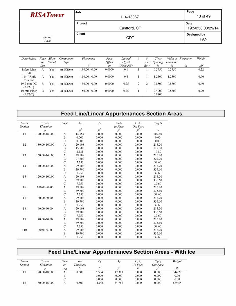
Feed Line/Linear Appurtenances - Entered As Round Or Flat
Description Face or
Leg
Allow Shield
Component Type
Placement
ft
Face Offset
in
Lateral Offset
(Frac FW)
# # Per Row
Clear Spacing
in
Width or Diameter
in
Perimeter
in
Weight
plf LDF7-50A
(1-5/8 FOAM) (Verizon)
A Yes Ar (CfAe) 190.00 - 0.00 1.5000 -0.15 12 8 1.0000 1.9800 0.82
LDF6-50A (1-1/4 FOAM)
(Nextel)
B Yes Ar (CfAe) 180.00 - 0.00 1.5000 -0.15 9 6 1.0000 1.5500 0.66
1 1/4 (Sprint)
C Yes Ar (CfAe) 165.50 - 0.00 1.5000 0 3 3 1.0000 1.5500 0.66
LDF7-50A (1-5/8 FOAM)
(AT&T)
B Yes Ar (CfAe) 150.00 - 0.00 1.5000 0.25 12 6 1.0000 1.9800 0.82
RRIISSAATToowweerr Job 114-13067
Page 13 of 49
Project Eastford, CT
Date 19:50:58 03/29/14
Phone: FAX:
Client CDT
Designed by FAN
Description Face or
Leg
Allow Shield
Component Type
Placement
ft
Face Offset
in
Lateral Offset
(Frac FW)
# # Per Row
Clear Spacing
in
Width or Diameter
in
Perimeter
in
Weight
plf Safety Line
3/8 A Yes Ar (CfAe) 190.00 - 0.00 0.0000 0.1 1 1 0.3750 0.3750 0.22
1 1/4'' Rigid Conduit
A Yes Ar (CfAe) 190.00 - 0.00 0.0000 0.4 1 1 1.2500 1.2500 0.70
19.7 mm DC (AT&T)
B Yes Ar (CfAe) 150.00 - 0.00 0.0000 0.25 2 2 0.8800 0.8800 0.40
10 mm Fiber (AT&T)
B Yes Ar (CfAe) 150.00 - 0.00 0.0000 0.25 1 1 0.4000 0.8800
0.8800 0.20
Feed Line/Linear Appurtenances Section Areas Tower Section
Tower Elevation
ft
Face AR
ft2
AF
ft2
CAAA In Face
ft2
CAAA Out Face
ft2
Weight
lb T1 190.00-180.00 A
B C
14.554 0.000 0.000
0.000 0.000 0.000
0.000 0.000 0.000
0.000 0.000 0.000
107.60 0.00 0.00
T2 180.00-160.00 A B C
29.108 15.500 2.131
0.000 0.000 0.000
0.000 0.000 0.000
0.000 0.000 0.000
215.20 118.80 10.89
T3 160.00-140.00 A B C
29.108 27.600 7.750
0.000 0.000 0.000
0.000 0.000 0.000
0.000 0.000 0.000
215.20 227.20 39.60
T4 140.00-120.00 A B C
29.108 39.700 7.750
0.000 0.000 0.000
0.000 0.000 0.000
0.000 0.000 0.000
215.20 335.60 39.60
T5 120.00-100.00 A B C
29.108 39.700 7.750
0.000 0.000 0.000
0.000 0.000 0.000
0.000 0.000 0.000
215.20 335.60 39.60
T6 100.00-80.00 A B C
29.108 39.700 7.750
0.000 0.000 0.000
0.000 0.000 0.000
0.000 0.000 0.000
215.20 335.60 39.60
T7 80.00-60.00 A B C
29.108 39.700 7.750
0.000 0.000 0.000
0.000 0.000 0.000
0.000 0.000 0.000
215.20 335.60 39.60
T8 60.00-40.00 A B C
29.108 39.700 7.750
0.000 0.000 0.000
0.000 0.000 0.000
0.000 0.000 0.000
215.20 335.60 39.60
T9 40.00-20.00 A B C
29.108 39.700 7.750
0.000 0.000 0.000
0.000 0.000 0.000
0.000 0.000 0.000
215.20 335.60 39.60
T10 20.00-0.00 A B C
29.108 39.700 7.750
0.000 0.000 0.000
0.000 0.000 0.000
0.000 0.000 0.000
215.20 335.60 39.60
Feed Line/Linear Appurtenances Section Areas - With Ice Tower Section
Tower Elevation
ft
Face or
Leg
Ice Thickness
in
AR
ft2
AF
ft2
CAAA In Face
ft2
CAAA Out Face
ft2
Weight
lb T1 190.00-180.00 A
B C
0.500 5.504 0.000 0.000
17.383 0.000 0.000
0.000 0.000 0.000
0.000 0.000 0.000
344.77 0.00 0.00
T2 180.00-160.00 A 0.500 11.008 34.767 0.000 0.000 689.55
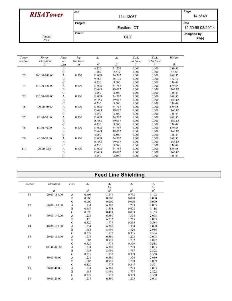
RRIISSAATToowweerr Job 114-13067
Page 14 of 49
Project Eastford, CT
Date 19:50:58 03/29/14
Phone: FAX:
Client CDT
Designed by FAN
Tower Section
Tower Elevation
ft
Face or
Leg
Ice Thickness
in
AR
ft2
AF
ft2
CAAA In Face
ft2
CAAA Out Face
ft2
Weight
lb B C
4.250 1.169
21.250 2.337
0.000 0.000
0.000 0.000
380.52 37.52
T3 160.00-140.00 A B C
0.500 11.008 9.867 4.250
34.767 35.133 8.500
0.000 0.000 0.000
0.000 0.000 0.000
689.55 772.19 136.44
T4 140.00-120.00 A B C
0.500 11.008 15.483 4.250
34.767 49.017 8.500
0.000 0.000 0.000
0.000 0.000 0.000
689.55 1163.85 136.44
T5 120.00-100.00 A B C
0.500 11.008 15.483 4.250
34.767 49.017 8.500
0.000 0.000 0.000
0.000 0.000 0.000
689.55 1163.85 136.44
T6 100.00-80.00 A B C
0.500 11.008 15.483 4.250
34.767 49.017 8.500
0.000 0.000 0.000
0.000 0.000 0.000
689.55 1163.85 136.44
T7 80.00-60.00 A B C
0.500 11.008 15.483 4.250
34.767 49.017 8.500
0.000 0.000 0.000
0.000 0.000 0.000
689.55 1163.85 136.44
T8 60.00-40.00 A B C
0.500 11.008 15.483 4.250
34.767 49.017 8.500
0.000 0.000 0.000
0.000 0.000 0.000
689.55 1163.85 136.44
T9 40.00-20.00 A B C
0.500 11.008 15.483 4.250
34.767 49.017 8.500
0.000 0.000 0.000
0.000 0.000 0.000
689.55 1163.85 136.44
T10 20.00-0.00 A B C
0.500 11.008 15.483 4.250
34.767 49.017 8.500
0.000 0.000 0.000
0.000 0.000 0.000
689.55 1163.85 136.44
Feed Line Shielding
Section Elevation
ft
Face AR
ft2
AR Ice ft2
AF
ft2
AF Ice ft2
T1 190.00-180.00 A B C
0.606 0.000 0.000
3.241 0.000 0.000
0.758 0.000 0.000
1.192 0.000 0.000
T2 180.00-160.00 A B C
1.234 0.657 0.090
6.380 3.554 0.489
1.273 0.678 0.093
2.003 1.116 0.153
T3 160.00-140.00 A B C
1.234 1.170 0.329
6.380 6.272 1.777
1.334 1.265 0.355
2.098 2.063 0.584
T4 140.00-120.00 A B C
1.234 1.683 0.329
6.380 8.991 1.777
1.334 1.820 0.355
2.098 2.956 0.584
T5 120.00-100.00 A B C
1.234 1.683 0.329
6.380 8.991 1.777
1.273 1.737 0.339
2.003 2.822 0.558
T6 100.00-80.00 A B C
1.234 1.683 0.329
6.380 8.991 1.777
1.273 1.737 0.339
2.003 2.822 0.558
T7 80.00-60.00 A B C
1.234 1.683 0.329
6.380 8.991 1.777
1.304 1.778 0.347
2.050 2.889 0.571
T8 60.00-40.00 A B C
1.234 1.683 0.329
6.380 8.991 1.777
1.273 1.737 0.339
2.003 2.822 0.558
T9 40.00-20.00 A 1.234 6.380 1.273 2.003
RRIISSAATToowweerr Job 114-13067
Page 15 of 49
Project Eastford, CT
Date 19:50:58 03/29/14
Phone: FAX:
Client CDT
Designed by FAN
Section Elevation
ft
Face AR
ft2
AR Ice ft2
AF
ft2
AF Ice ft2
B C
1.683 0.329
8.991 1.777
1.737 0.339
2.822 0.558
T10 20.00-0.00 A B C
1.234 1.683 0.329
6.380 8.991 1.777
1.273 1.737 0.339
2.003 2.822 0.558
Feed Line Center of Pressure
Section Elevation
ft
CPX
in
CPZ
in
CPX Ice in
CPZ Ice in
T1 190.00-180.00 -5.7018 -1.4588 -4.2855 -1.3355 T2 180.00-160.00 -3.1108 -3.0382 -2.3682 -2.5784 T3 160.00-140.00 -0.6535 -1.7074 -0.6262 -1.6851 T4 140.00-120.00 1.1844 -1.4149 0.6893 -1.4399 T5 120.00-100.00 1.1897 -1.4212 0.6932 -1.4448 T6 100.00-80.00 1.1897 -1.4212 0.6932 -1.4448 T7 80.00-60.00 1.1870 -1.4180 0.6913 -1.4423 T8 60.00-40.00 1.1897 -1.4212 0.6932 -1.4448 T9 40.00-20.00 1.1897 -1.4212 0.6932 -1.4448
T10 20.00-0.00 1.1897 -1.4212 0.6932 -1.4448
Discrete Tower Loads
Description Face or
Leg
Offset Type
Offsets: Horz
Lateral Vert
ft ft ft
Azimuth Adjustment
°
Placement
ft
CAAA Front
ft2
CAAA Side
ft2
Weight
lb
Antel BXA-70063-6CF (Verizon)
A From Leg 3.00 0.00 0.00
0.0000 193.00 No Ice 1/2'' Ice
7.57 8.02
2.21 2.70
17.00 57.60
Antel BXA-70063-6CF (Verizon)
B From Leg 3.00 0.00 0.00
0.0000 193.00 No Ice 1/2'' Ice
7.57 8.02
2.21 2.70
17.00 57.60
Antel BXA-70063-6CF (Verizon)
C From Leg 3.00 0.00 0.00
0.0000 193.00 No Ice 1/2'' Ice
7.57 8.02
2.21 2.70
17.00 57.60
Sector Frame (Verizon)
A From Leg 0.00 0.00 0.00
0.0000 193.00 No Ice 1/2'' Ice
13.60 18.40
13.60 18.40
465.00 600.00
Sector Frame (Verizon)
B From Leg 0.00 0.00 0.00
0.0000 193.00 No Ice 1/2'' Ice
13.60 18.40
13.60 18.40
465.00 600.00
Sector Frame (Verizon)
C From Leg 0.00 0.00 0.00
0.0000 193.00 No Ice 1/2'' Ice
13.60 18.40
13.60 18.40
465.00 600.00
(2) Antel LPA-80080-6CF (Verizon)
A From Leg 3.00 0.00 0.00
0.0000 193.00 No Ice 1/2'' Ice
4.33 4.80
8.62 9.07
21.00 69.20
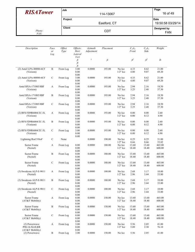
RRIISSAATToowweerr Job 114-13067
Page 16 of 49
Project Eastford, CT
Date 19:50:58 03/29/14
Phone: FAX:
Client CDT
Designed by FAN
Description Face or
Leg
Offset Type
Offsets: Horz
Lateral Vert
ft ft ft
Azimuth Adjustment
°
Placement
ft
CAAA Front
ft2
CAAA Side
ft2
Weight
lb
(2) Antel LPA-80080-6CF (Verizon)
B From Leg 3.00 0.00 0.00
0.0000 193.00 No Ice 1/2'' Ice
4.33 4.80
8.62 9.07
21.00 69.20
(2) Antel LPA-80080-6CF (Verizon)
C From Leg 3.00 0.00 0.00
0.0000 193.00 No Ice 1/2'' Ice
4.33 4.80
8.62 9.07
21.00 69.20
Antel BXA-171085/8BF (Verizon)
A From Leg 3.00 0.00 0.00
0.0000 193.00 No Ice 1/2'' Ice
2.94 3.25
2.16 2.48
18.50 37.30
Antel BXA-171085/8BF (Verizon)
B From Leg 3.00 0.00 0.00
0.0000 193.00 No Ice 1/2'' Ice
2.94 3.25
2.16 2.48
18.50 37.30
Antel BXA-171085/8BF (Verizon)
C From Leg 3.00 0.00 0.00
0.0000 193.00 No Ice 1/2'' Ice
2.94 3.25
2.16 2.48
18.50 37.30
(2) RFS FD9R6004/2C-3L (Verizon)
A From Leg 3.00 0.00 0.00
0.0000 193.00 No Ice 1/2'' Ice
0.00 0.00
0.08 0.12
2.60 4.90
(2) RFS FD9R6004/2C-3L (Verizon)
B From Leg 3.00 0.00 0.00
0.0000 193.00 No Ice 1/2'' Ice
0.00 0.00
0.08 0.12
2.60 4.90
(2) RFS FD9R6004/2C-3L (Verizon)
C From Leg 3.00 0.00 0.00
0.0000 193.00 No Ice 1/2'' Ice
0.00 0.00
0.08 0.12
2.60 4.90
Lightning Rod 5/8x4' C None 0.0000 190.00 No Ice 1/2'' Ice
0.25 0.66
0.25 0.66
31.00 33.82
Sector Frame (Nextel)
A From Leg 0.00 0.00 0.00
0.0000 180.00 No Ice 1/2'' Ice
13.60 18.40
13.60 18.40
465.00 600.00
Sector Frame (Nextel)
B From Leg 0.00 0.00 0.00
0.0000 180.00 No Ice 1/2'' Ice
13.60 18.40
13.60 18.40
465.00 600.00
Sector Frame (Nextel)
C From Leg 0.00 0.00 0.00
0.0000 180.00 No Ice 1/2'' Ice
13.60 18.40
13.60 18.40
465.00 600.00
(3) Swedcom ALP-E-9011 (Nextel)
A From Leg 3.00 0.00 0.00
0.0000 180.00 No Ice 1/2'' Ice
2.68 2.96
3.17 3.44
10.00 33.80
(3) Swedcom ALP-E-9011 (Nextel)
B From Leg 3.00 0.00 0.00
0.0000 180.00 No Ice 1/2'' Ice
2.68 2.96
3.17 3.44
10.00 33.80
(3) Swedcom ALP-E-9011 (Nextel)
C From Leg 3.00 0.00 0.00
0.0000 180.00 No Ice 1/2'' Ice
2.68 2.96
3.17 3.44
10.00 33.80
Sector Frame (AT&T Mobility)
A From Leg 0.00 0.00 0.00
0.0000 150.00 No Ice 1/2'' Ice
13.60 18.40
13.60 18.40
465.00 600.00
Sector Frame (AT&T Mobility)
B From Leg 0.00 0.00 0.00
0.0000 150.00 No Ice 1/2'' Ice
13.60 18.40
13.60 18.40
465.00 600.00
Sector Frame (AT&T Mobility)
C From Leg 0.00 0.00 0.00
0.0000 150.00 No Ice 1/2'' Ice
13.60 18.40
13.60 18.40
465.00 600.00
(2) Powerwave P90-14-XLH-RR (AT&T Mobility)
A From Leg 3.00 0.00 0.00
0.0000 150.00 No Ice 1/2'' Ice
5.56 5.89
2.05 2.38
41.00 76.10
(2) Powerwave B From Leg 3.00 0.0000 150.00 No Ice 5.56 2.05 41.00
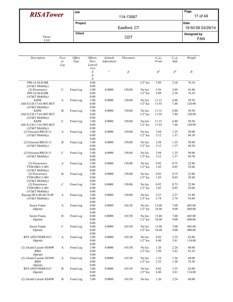
RRIISSAATToowweerr Job 114-13067
Page 17 of 49
Project Eastford, CT
Date 19:50:58 03/29/14
Phone: FAX:
Client CDT
Designed by FAN
Description Face or
Leg
Offset Type
Offsets: Horz
Lateral Vert
ft ft ft
Azimuth Adjustment
°
Placement
ft
CAAA Front
ft2
CAAA Side
ft2
Weight
lb
P90-14-XLH-RR (AT&T Mobility)
0.00 0.00
1/2'' Ice 5.89 2.38 76.10
(2) Powerwave P90-14-XLH-RR (AT&T Mobility)
C From Leg 3.00 0.00 0.00
0.0000 150.00 No Ice 1/2'' Ice
5.56 5.89
2.05 2.38
41.00 76.10
KMW AM-X-CD-17-65-00T-RET
(AT&T Mobility)
A From Leg 3.00 0.00 0.00
0.0000 150.00 No Ice 1/2'' Ice
11.31 11.93
6.80 7.48
59.50 120.90
KMW AM-X-CD-17-65-00T-RET
(AT&T Mobility)
B From Leg 3.00 0.00 0.00
0.0000 150.00 No Ice 1/2'' Ice
11.31 11.93
6.80 7.48
59.50 120.90
KMW AM-X-CD-17-65-00T-RET
(AT&T Mobility)
C From Leg 3.00 0.00 0.00
0.0000 150.00 No Ice 1/2'' Ice
11.31 11.93
6.80 7.48
59.50 120.90
(2) Ericsson RRUS-11 (AT&T Mobility)
A From Leg 3.00 0.00 0.00
0.0000 150.00 No Ice 1/2'' Ice
2.94 3.12
1.25 1.37
50.00 69.30
(2) Ericsson RRUS-11 (AT&T Mobility)
B From Leg 3.00 0.00 0.00
0.0000 150.00 No Ice 1/2'' Ice
2.94 3.12
1.25 1.37
50.00 69.30
(2) Ericsson RRUS-11 (AT&T Mobility)
C From Leg 3.00 0.00 0.00
0.0000 150.00 No Ice 1/2'' Ice
2.94 3.12
1.25 1.37
50.00 69.30
(2) Powerwave TT08-DB111-001 (AT&T Mobility)
A From Leg 3.00 0.00 0.00
0.0000 150.00 No Ice 1/2'' Ice
0.92 1.03
0.75 0.85
22.00 29.60
(2) Powerwave TT08-DB111-001 (AT&T Mobility)
B From Leg 3.00 0.00 0.00
0.0000 150.00 No Ice 1/2'' Ice
0.92 1.03
0.75 0.85
22.00 29.60
(2) Powerwave TT08-DB111-001 (AT&T Mobility)
C From Leg 3.00 0.00 0.00
0.0000 150.00 No Ice 1/2'' Ice
0.92 1.03
0.75 0.85
22.00 29.60
Raycap DC6-48-60-18-8F (AT&T Mobility)
A From Leg 3.00 0.00 0.00
0.0000 150.00 No Ice 1/2'' Ice
2.57 2.74
2.57 2.74
31.80 54.40
Sector Frame (Sprint)
A From Leg 0.00 0.00 0.00
0.0000 165.50 No Ice 1/2'' Ice
13.60 18.40
7.00 9.00
465.00 600.00
Sector Frame (Sprint)
B From Leg 0.00 0.00 0.00
0.0000 165.50 No Ice 1/2'' Ice
13.60 18.40
7.00 9.00
465.00 600.00
Sector Frame (Sprint)
C From Leg 0.00 0.00 0.00
0.0000 165.50 No Ice 1/2'' Ice
13.60 18.40
7.00 9.00
465.00 600.00
RFS APXV9ERR18-C (Sprint)
A From Leg 3.00 0.00 0.00
0.0000 165.50 No Ice 1/2'' Ice
8.02 8.48
3.35 3.81
62.00 114.00
(2) Alcatel Lucent 4X40W RRH
(Sprint)
A From Leg 3.00 0.00 0.00
0.0000 165.50 No Ice 1/2'' Ice
1.20 2.50
2.24 2.42
60.00 83.10
(2) Alcatel Lucent 2X50W RRH
(Sprint)
A From Leg 3.00 0.00 0.00
0.0000 165.50 No Ice 1/2'' Ice
1.10 2.22
1.36 1.50
60.00 78.30
RFS APXV9ERR18-C (Sprint)
B From Leg 3.00 0.00 0.00
0.0000 165.50 No Ice 1/2'' Ice
8.02 8.48
3.35 3.81
62.00 114.00
(2) Alcatel Lucent 4X40W B From Leg 3.00 0.0000 165.50 No Ice 1.20 2.24 60.00
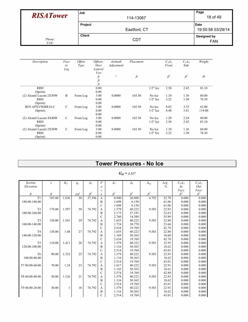
RRIISSAATToowweerr Job 114-13067
Page 18 of 49
Project Eastford, CT
Date 19:50:58 03/29/14
Phone: FAX:
Client CDT
Designed by FAN
Description Face or
Leg
Offset Type
Offsets: Horz
Lateral Vert
ft ft ft
Azimuth Adjustment
°
Placement
ft
CAAA Front
ft2
CAAA Side
ft2
Weight
lb
RRH (Sprint)
0.00 0.00
1/2'' Ice 2.50 2.42 83.10
(2) Alcatel Lucent 2X50W RRH
(Sprint)
B From Leg 3.00 0.00 0.00
0.0000 165.50 No Ice 1/2'' Ice
1.10 2.22
1.36 1.50
60.00 78.30
RFS APXV9ERR18-C (Sprint)
C From Leg 3.00 0.00 0.00
0.0000 165.50 No Ice 1/2'' Ice
8.02 8.48
3.35 3.81
62.00 114.00
(2) Alcatel Lucent 4X40W RRH
(Sprint)
C From Leg 3.00 0.00 0.00
0.0000 165.50 No Ice 1/2'' Ice
1.20 2.50
2.24 2.42
60.00 83.10
(2) Alcatel Lucent 2X50W RRH
(Sprint)
C From Leg 3.00 0.00 0.00
0.0000 165.50 No Ice 1/2'' Ice
1.10 2.22
1.36 1.50
60.00 78.30
Tower Pressures - No Ice
GH = 1.117
Section Elevation
ft
z
ft
KZ
qz
psf
AG
ft2
Face
AF
ft2
AR
ft2
Aleg
ft2
Leg %
CAAA In
Face ft2
CAAA Out Face
ft2 T1
190.00-180.00 185.00 1.636 30 37.396 A
B C
0.9401.6981.698
20.0986.1506.150
4.792 22.7861.0661.06
0.000 0.000 0.000
0.0000.0000.000
T2 180.00-160.00
170.00 1.597 30 74.792 A B C
1.5792.1752.760
40.22227.19114.389
9.583 22.9332.6355.89
0.000 0.000 0.000
0.0000.0000.000
T3 160.00-140.00
150.00 1.541 29 74.792 A B C
1.6551.7242.634
40.22238.77819.769
9.583 22.8823.6642.78
0.000 0.000 0.000
0.0000.0000.000
T4 140.00-120.00
130.00 1.48 27 74.792 A B C
1.6551.1692.634
40.22250.36519.769
9.583 22.8818.6042.78
0.000 0.000 0.000
0.0000.0000.000
T5 120.00-100.00
110.00 1.411 26 74.792 A B C
1.5791.1162.514
40.22250.36519.769
9.583 22.9318.6243.01
0.000 0.000 0.000
0.0000.0000.000
T6 100.00-80.00
90.00 1.332 25 74.792 A B C
1.5791.1162.514
40.22250.36519.769
9.583 22.9318.6243.01
0.000 0.000 0.000
0.0000.0000.000
T7 80.00-60.00 70.00 1.24 23 74.792 A B C
1.6171.1432.574
40.22250.36519.769
9.583 22.9118.6142.89
0.000 0.000 0.000
0.0000.0000.000
T8 60.00-40.00 50.00 1.126 21 74.792 A B C
1.5791.1162.514
40.22250.36519.769
9.583 22.9318.6243.01
0.000 0.000 0.000
0.0000.0000.000
T9 40.00-20.00 30.00 1 18 74.792 A B C
1.5791.1162.514
40.22250.36519.769
9.583 22.9318.6243.01
0.000 0.000 0.000
0.0000.0000.000
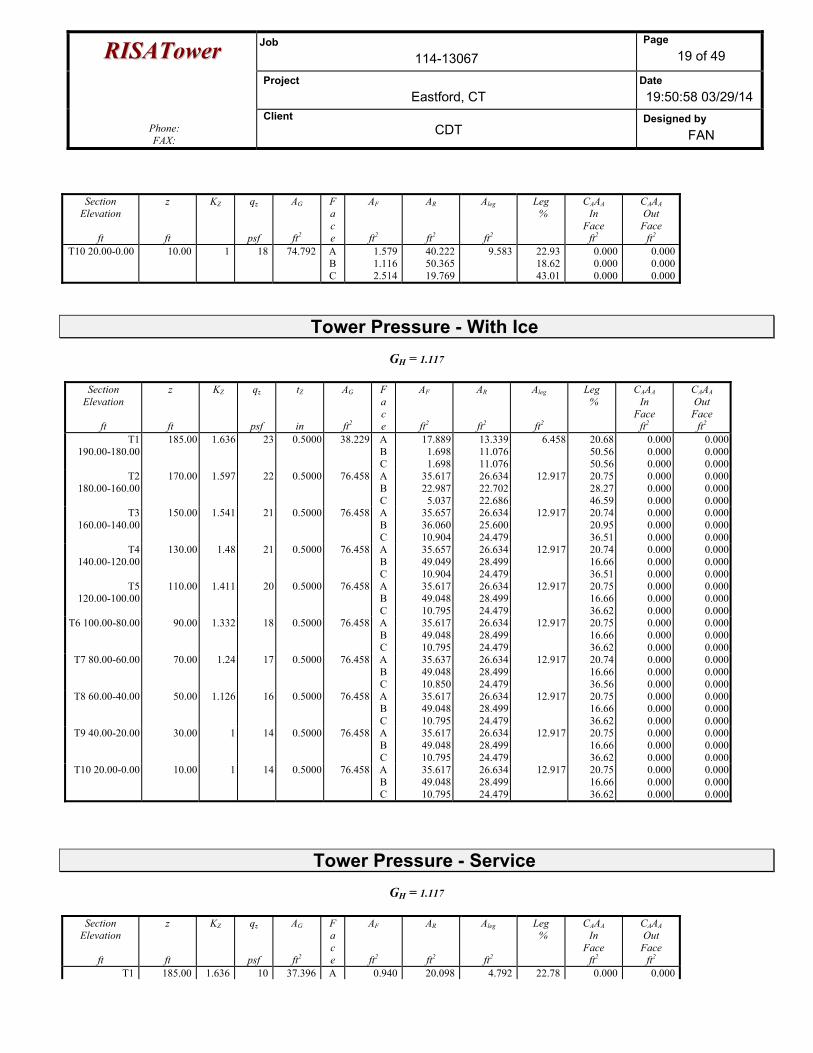
RRIISSAATToowweerr Job 114-13067
Page 19 of 49
Project Eastford, CT
Date 19:50:58 03/29/14
Phone: FAX:
Client CDT
Designed by FAN
Section Elevation
ft
z
ft
KZ
qz
psf
AG
ft2
Face
AF
ft2
AR
ft2
Aleg
ft2
Leg %
CAAA In
Face ft2
CAAA Out Face
ft2 T10 20.00-0.00 10.00 1 18 74.792 A
B C
1.5791.1162.514
40.22250.36519.769
9.583 22.9318.6243.01
0.000 0.000 0.000
0.0000.0000.000
Tower Pressure - With Ice
GH = 1.117
Section Elevation
ft
z
ft
KZ
qz
psf
tZ
in
AG
ft2
Face
AF
ft2
AR
ft2
Aleg
ft2
Leg %
CAAA In
Face ft2
CAAA Out Face
ft2 T1
190.00-180.00 185.00 1.636 23 0.5000 38.229 A
B C
17.8891.6981.698
13.33911.07611.076
6.458 20.68 50.56 50.56
0.0000.0000.000
0.0000.0000.000
T2 180.00-160.00
170.00 1.597 22 0.5000 76.458 A B C
35.61722.987
5.037
26.63422.70222.686
12.917 20.75 28.27 46.59
0.0000.0000.000
0.0000.0000.000
T3 160.00-140.00
150.00 1.541 21 0.5000 76.458 A B C
35.65736.06010.904
26.63425.60024.479
12.917 20.74 20.95 36.51
0.0000.0000.000
0.0000.0000.000
T4 140.00-120.00
130.00 1.48 21 0.5000 76.458 A B C
35.65749.04910.904
26.63428.49924.479
12.917 20.74 16.66 36.51
0.0000.0000.000
0.0000.0000.000
T5 120.00-100.00
110.00 1.411 20 0.5000 76.458 A B C
35.61749.04810.795
26.63428.49924.479
12.917 20.75 16.66 36.62
0.0000.0000.000
0.0000.0000.000
T6 100.00-80.00 90.00 1.332 18 0.5000 76.458 A B C
35.61749.04810.795
26.63428.49924.479
12.917 20.75 16.66 36.62
0.0000.0000.000
0.0000.0000.000
T7 80.00-60.00 70.00 1.24 17 0.5000 76.458 A B C
35.63749.04810.850
26.63428.49924.479
12.917 20.74 16.66 36.56
0.0000.0000.000
0.0000.0000.000
T8 60.00-40.00 50.00 1.126 16 0.5000 76.458 A B C
35.61749.04810.795
26.63428.49924.479
12.917 20.75 16.66 36.62
0.0000.0000.000
0.0000.0000.000
T9 40.00-20.00 30.00 1 14 0.5000 76.458 A B C
35.61749.04810.795
26.63428.49924.479
12.917 20.75 16.66 36.62
0.0000.0000.000
0.0000.0000.000
T10 20.00-0.00 10.00 1 14 0.5000 76.458 A B C
35.61749.04810.795
26.63428.49924.479
12.917 20.75 16.66 36.62
0.0000.0000.000
0.0000.0000.000
Tower Pressure - Service
GH = 1.117
Section Elevation
ft
z
ft
KZ
qz
psf
AG
ft2
Face
AF
ft2
AR
ft2
Aleg
ft2
Leg %
CAAA In
Face ft2
CAAA Out Face
ft2 T1 185.00 1.636 10 37.396 A 0.940 20.098 4.792 22.78 0.000 0.000

RRIISSAATToowweerr Job 114-13067
Page 20 of 49
Project Eastford, CT
Date 19:50:58 03/29/14
Phone: FAX:
Client CDT
Designed by FAN
Section Elevation
ft
z
ft
KZ
qz
psf
AG
ft2
Face
AF
ft2
AR
ft2
Aleg
ft2
Leg %
CAAA In
Face ft2
CAAA Out Face
ft2 190.00-180.00 B
C 1.6981.698
6.1506.150
61.0661.06
0.000 0.000
0.0000.000
T2 180.00-160.00
170.00 1.597 10 74.792 A B C
1.5792.1752.760
40.22227.19114.389
9.583 22.9332.6355.89
0.000 0.000 0.000
0.0000.0000.000
T3 160.00-140.00
150.00 1.541 10 74.792 A B C
1.6551.7242.634
40.22238.77819.769
9.583 22.8823.6642.78
0.000 0.000 0.000
0.0000.0000.000
T4 140.00-120.00
130.00 1.48 9 74.792 A B C
1.6551.1692.634
40.22250.36519.769
9.583 22.8818.6042.78
0.000 0.000 0.000
0.0000.0000.000
T5 120.00-100.00
110.00 1.411 9 74.792 A B C
1.5791.1162.514
40.22250.36519.769
9.583 22.9318.6243.01
0.000 0.000 0.000
0.0000.0000.000
T6 100.00-80.00
90.00 1.332 9 74.792 A B C
1.5791.1162.514
40.22250.36519.769
9.583 22.9318.6243.01
0.000 0.000 0.000
0.0000.0000.000
T7 80.00-60.00 70.00 1.24 8 74.792 A B C
1.6171.1432.574
40.22250.36519.769
9.583 22.9118.6142.89
0.000 0.000 0.000
0.0000.0000.000
T8 60.00-40.00 50.00 1.126 7 74.792 A B C
1.5791.1162.514
40.22250.36519.769
9.583 22.9318.6243.01
0.000 0.000 0.000
0.0000.0000.000
T9 40.00-20.00 30.00 1 6 74.792 A B C
1.5791.1162.514
40.22250.36519.769
9.583 22.9318.6243.01
0.000 0.000 0.000
0.0000.0000.000
T10 20.00-0.00 10.00 1 6 74.792 A B C
1.5791.1162.514
40.22250.36519.769
9.583 22.9318.6243.01
0.000 0.000 0.000
0.0000.0000.000
Tower Forces - No Ice - Wind Normal To Face
Section Elevation
ft
Add Weight
lb
Self Weight
lb
F a c e
e CF
RR DF
DR
AE
ft2
F
lb
w
plf
Ctrl. Face
T1 190.00-180.00
107.60 340.32 A B C
0.563 0.21 0.21
1.8322.5632.563
0.7310.5920.592
111
111
15.6405.3415.341
968.89 96.89 A
T2 180.00-160.00
344.89 658.24 A B C
0.559 0.393 0.229
1.8352.0792.501
0.7290.6490.597
111
111
30.91419.81111.347
1872.74 93.64 A
T3 160.00-140.00
482.00 680.49 TA 242.49
A B C
0.56 0.542
0.3
1.8341.8522.297
0.730.72
0.616
111
111
31.01229.62614.807
1811.80 90.59 A
T4 140.00-120.00
590.40 680.49 TA 242.49
A B C
0.56 0.689
0.3
1.8341.7762.297
0.730.8120.616
111
111
31.01242.07214.807
2284.14 114.21 B
T5 120.00-100.00
590.40 658.24 A B C
0.559 0.688 0.298
1.8351.7762.302
0.7290.8120.615
111
111
30.91441.99414.677
2173.64 108.68 B
T6 100.00-80.00
590.40 658.24 A B C
0.559 0.688 0.298
1.8351.7762.302
0.7290.8120.615
111
111
30.91441.99414.677
2052.52 102.63 B
T7 80.00-60.00
590.40 661.59 A B C
0.559 0.689 0.299
1.8351.7762.299
0.730.8120.616
111
111
30.96342.03314.742
1912.08 95.60 B
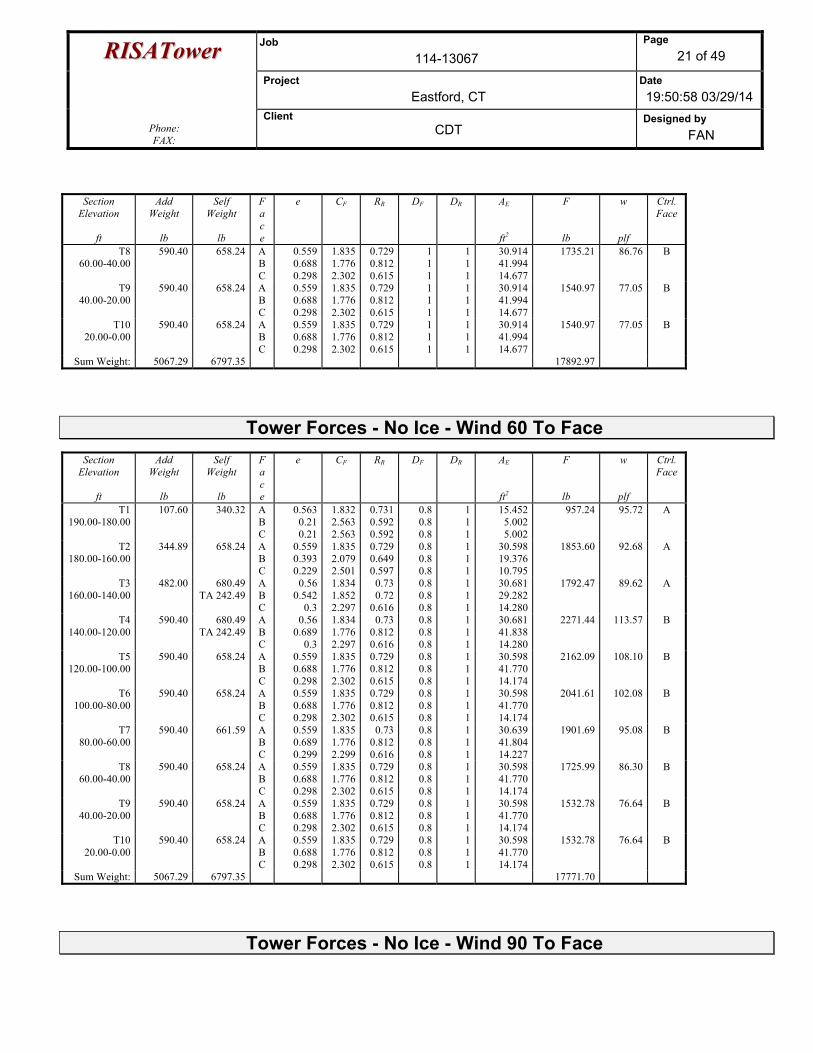
RRIISSAATToowweerr Job 114-13067
Page 21 of 49
Project Eastford, CT
Date 19:50:58 03/29/14
Phone: FAX:
Client CDT
Designed by FAN
Section Elevation
ft
Add Weight
lb
Self Weight
lb
F a c e
e CF
RR DF
DR
AE
ft2
F
lb
w
plf
Ctrl. Face
T8 60.00-40.00
590.40 658.24 A B C
0.559 0.688 0.298
1.8351.7762.302
0.7290.8120.615
111
111
30.91441.99414.677
1735.21 86.76 B
T9 40.00-20.00
590.40 658.24 A B C
0.559 0.688 0.298
1.8351.7762.302
0.7290.8120.615
111
111
30.91441.99414.677
1540.97 77.05 B
T10 20.00-0.00
590.40 658.24 A B C
0.559 0.688 0.298
1.8351.7762.302
0.7290.8120.615
111
111
30.91441.99414.677
1540.97 77.05 B
Sum Weight: 5067.29 6797.35 17892.97
Tower Forces - No Ice - Wind 60 To Face
Section Elevation
ft
Add Weight
lb
Self Weight
lb
F a c e
e CF
RR DF
DR
AE
ft2
F
lb
w
plf
Ctrl. Face
T1 190.00-180.00
107.60 340.32 A B C
0.563 0.21 0.21
1.8322.5632.563
0.7310.5920.592
0.80.80.8
111
15.4525.0025.002
957.24 95.72 A
T2 180.00-160.00
344.89 658.24 A B C
0.559 0.393 0.229
1.8352.0792.501
0.7290.6490.597
0.80.80.8
111
30.59819.37610.795
1853.60 92.68 A
T3 160.00-140.00
482.00 680.49 TA 242.49
A B C
0.56 0.542
0.3
1.8341.8522.297
0.730.72
0.616
0.80.80.8
111
30.68129.28214.280
1792.47 89.62 A
T4 140.00-120.00
590.40 680.49 TA 242.49
A B C
0.56 0.689
0.3
1.8341.7762.297
0.730.8120.616
0.80.80.8
111
30.68141.83814.280
2271.44 113.57 B
T5 120.00-100.00
590.40 658.24 A B C
0.559 0.688 0.298
1.8351.7762.302
0.7290.8120.615
0.80.80.8
111
30.59841.77014.174
2162.09 108.10 B
T6 100.00-80.00
590.40 658.24 A B C
0.559 0.688 0.298
1.8351.7762.302
0.7290.8120.615
0.80.80.8
111
30.59841.77014.174
2041.61 102.08 B
T7 80.00-60.00
590.40 661.59 A B C
0.559 0.689 0.299
1.8351.7762.299
0.730.8120.616
0.80.80.8
111
30.63941.80414.227
1901.69 95.08 B
T8 60.00-40.00
590.40 658.24 A B C
0.559 0.688 0.298
1.8351.7762.302
0.7290.8120.615
0.80.80.8
111
30.59841.77014.174
1725.99 86.30 B
T9 40.00-20.00
590.40 658.24 A B C
0.559 0.688 0.298
1.8351.7762.302
0.7290.8120.615
0.80.80.8
111
30.59841.77014.174
1532.78 76.64 B
T10 20.00-0.00
590.40 658.24 A B C
0.559 0.688 0.298
1.8351.7762.302
0.7290.8120.615
0.80.80.8
111
30.59841.77014.174
1532.78 76.64 B
Sum Weight: 5067.29 6797.35 17771.70
Tower Forces - No Ice - Wind 90 To Face
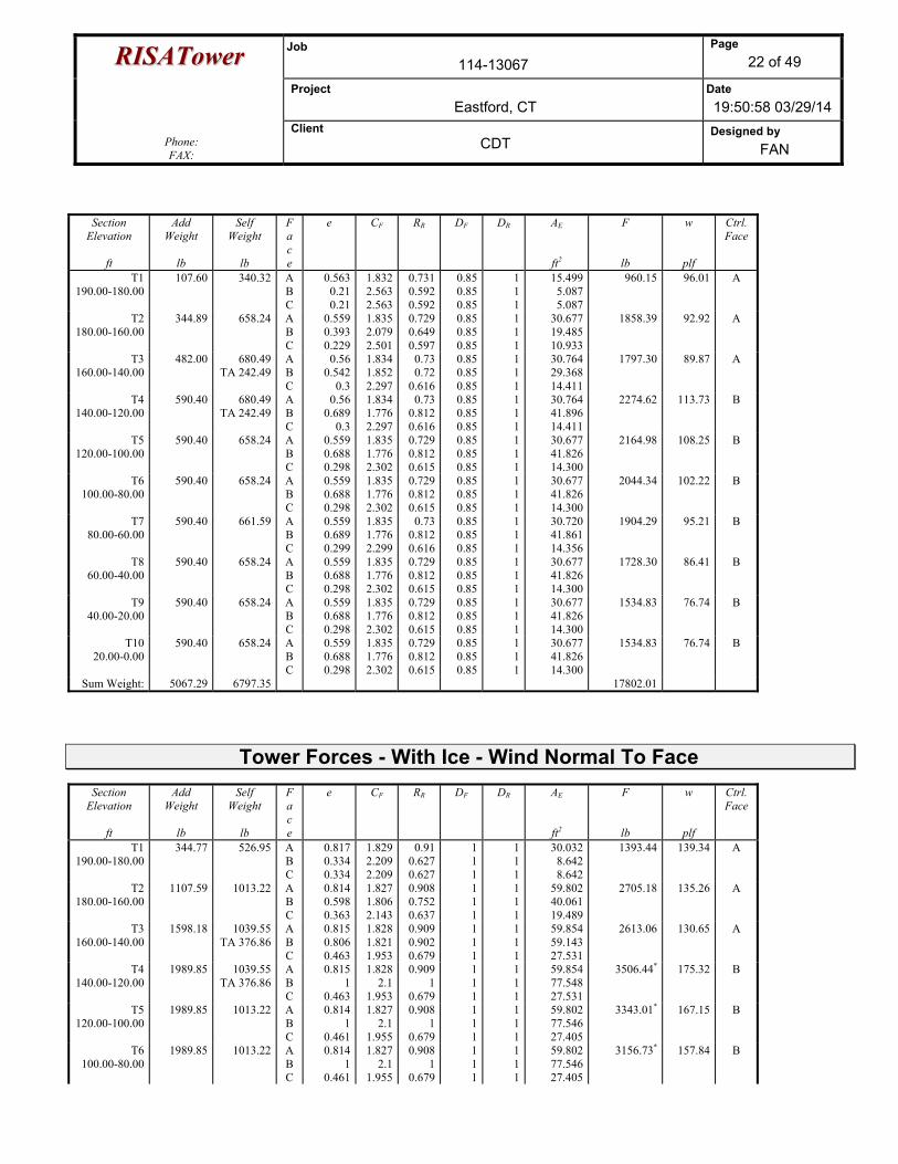
RRIISSAATToowweerr Job 114-13067
Page 22 of 49
Project Eastford, CT
Date 19:50:58 03/29/14
Phone: FAX:
Client CDT
Designed by FAN
Section Elevation
ft
Add Weight
lb
Self Weight
lb
F a c e
e CF
RR DF
DR
AE
ft2
F
lb
w
plf
Ctrl. Face
T1 190.00-180.00
107.60 340.32 A B C
0.563 0.21 0.21
1.8322.5632.563
0.7310.5920.592
0.850.850.85
111
15.4995.0875.087
960.15 96.01 A
T2 180.00-160.00
344.89 658.24 A B C
0.559 0.393 0.229
1.8352.0792.501
0.7290.6490.597
0.850.850.85
111
30.67719.48510.933
1858.39 92.92 A
T3 160.00-140.00
482.00 680.49 TA 242.49
A B C
0.56 0.542
0.3
1.8341.8522.297
0.730.72
0.616
0.850.850.85
111
30.76429.36814.411
1797.30 89.87 A
T4 140.00-120.00
590.40 680.49 TA 242.49
A B C
0.56 0.689
0.3
1.8341.7762.297
0.730.8120.616
0.850.850.85
111
30.76441.89614.411
2274.62 113.73 B
T5 120.00-100.00
590.40 658.24 A B C
0.559 0.688 0.298
1.8351.7762.302
0.7290.8120.615
0.850.850.85
111
30.67741.82614.300
2164.98 108.25 B
T6 100.00-80.00
590.40 658.24 A B C
0.559 0.688 0.298
1.8351.7762.302
0.7290.8120.615
0.850.850.85
111
30.67741.82614.300
2044.34 102.22 B
T7 80.00-60.00
590.40 661.59 A B C
0.559 0.689 0.299
1.8351.7762.299
0.730.8120.616
0.850.850.85
111
30.72041.86114.356
1904.29 95.21 B
T8 60.00-40.00
590.40 658.24 A B C
0.559 0.688 0.298
1.8351.7762.302
0.7290.8120.615
0.850.850.85
111
30.67741.82614.300
1728.30 86.41 B
T9 40.00-20.00
590.40 658.24 A B C
0.559 0.688 0.298
1.8351.7762.302
0.7290.8120.615
0.850.850.85
111
30.67741.82614.300
1534.83 76.74 B
T10 20.00-0.00
590.40 658.24 A B C
0.559 0.688 0.298
1.8351.7762.302
0.7290.8120.615
0.850.850.85
111
30.67741.82614.300
1534.83 76.74 B
Sum Weight: 5067.29 6797.35 17802.01
Tower Forces - With Ice - Wind Normal To Face
Section Elevation
ft
Add Weight
lb
Self Weight
lb
F a c e
e CF
RR DF
DR
AE
ft2
F
lb
w
plf
Ctrl. Face
T1 190.00-180.00
344.77 526.95 A B C
0.817 0.334 0.334
1.8292.2092.209
0.910.6270.627
111
111
30.0328.6428.642
1393.44 139.34 A
T2 180.00-160.00
1107.59 1013.22 A B C
0.814 0.598 0.363
1.8271.8062.143
0.9080.7520.637
111
111
59.80240.06119.489
2705.18 135.26 A
T3 160.00-140.00
1598.18 1039.55 TA 376.86
A B C
0.815 0.806 0.463
1.8281.8211.953
0.9090.9020.679
111
111
59.85459.14327.531
2613.06 130.65 A
T4 140.00-120.00
1989.85 1039.55 TA 376.86
A B C
0.815 1
0.463
1.8282.1
1.953
0.9091
0.679
111
111
59.85477.54827.531
3506.44* 175.32 B
T5 120.00-100.00
1989.85 1013.22 A B C
0.814 1
0.461
1.8272.1
1.955
0.9081
0.679
111
111
59.80277.54627.405
3343.01* 167.15 B
T6 100.00-80.00
1989.85 1013.22 A B C
0.814 1
0.461
1.8272.1
1.955
0.9081
0.679
111
111
59.80277.54627.405
3156.73* 157.84 B
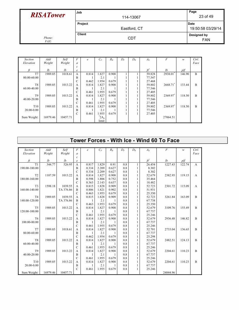
RRIISSAATToowweerr Job 114-13067
Page 23 of 49
Project Eastford, CT
Date 19:50:58 03/29/14
Phone: FAX:
Client CDT
Designed by FAN
Section Elevation
ft
Add Weight
lb
Self Weight
lb
F a c e
e CF
RR DF
DR
AE
ft2
F
lb
w
plf
Ctrl. Face
T7 80.00-60.00
1989.85 1018.61 A B C
0.814 1
0.462
1.8272.1
1.954
0.9081
0.679
111
111
59.82877.54727.468
2938.01* 146.90 B
T8 60.00-40.00
1989.85 1013.22 A B C
0.814 1
0.461
1.8272.1
1.955
0.9081
0.679
111
111
59.80277.54627.405
2668.71* 133.44 B
T9 40.00-20.00
1989.85 1013.22 A B C
0.814 1
0.461
1.8272.1
1.955
0.9081
0.679
111
111
59.80277.54627.405
2369.97* 118.50 B
T10 20.00-0.00
1989.85 1013.22 A B C
0.814 1
0.461
1.8272.1
1.955
0.9081
0.679
111
111
59.80277.54627.405
2369.97* 118.50 B
Sum Weight: 16979.46 10457.71 *2Ag limit
27064.51
Tower Forces - With Ice - Wind 60 To Face
Section Elevation
ft
Add Weight
lb
Self Weight
lb
F a c e
e CF
RR DF
DR
AE
ft2
F
lb
w
plf
Ctrl. Face
T1 190.00-180.00
344.77 526.95 A B C
0.817 0.334 0.334
1.8292.2092.209
0.910.6270.627
0.80.80.8
111
26.4548.3028.302
1227.43 122.74 A
T2 180.00-160.00
1107.59 1013.22 A B C
0.814 0.598 0.363
1.8271.8062.143
0.9080.7520.637
0.80.80.8
111
52.67935.46418.482
2382.95 119.15 A
T3 160.00-140.00
1598.18 1039.55 TA 376.86
A B C
0.815 0.806 0.463
1.8281.8211.953
0.9090.9020.679
0.80.80.8
111
52.72351.93125.350
2301.72 115.09 A
T4 140.00-120.00
1989.85 1039.55 TA 376.86
A B C
0.815 1
0.463
1.8282.1
1.953
0.9091
0.679
0.80.80.8
111
52.72367.73825.350
3261.84 163.09 B
T5 120.00-100.00
1989.85 1013.22 A B C
0.814 1
0.461
1.8272.1
1.955
0.9081
0.679
0.80.80.8
111
52.67967.73725.246
3109.76 155.49 B
T6 100.00-80.00
1989.85 1013.22 A B C
0.814 1
0.461
1.8272.1
1.955
0.9081
0.679
0.80.80.8
111
52.67967.73725.246
2936.48 146.82 B
T7 80.00-60.00
1989.85 1018.61 A B C
0.814 1
0.462
1.8272.1
1.954
0.9081
0.679
0.80.80.8
111
52.70167.73725.298
2733.04 136.65 B
T8 60.00-40.00
1989.85 1013.22 A B C
0.814 1
0.461
1.8272.1
1.955
0.9081
0.679
0.80.80.8
111
52.67967.73725.246
2482.51 124.13 B
T9 40.00-20.00
1989.85 1013.22 A B C
0.814 1
0.461
1.8272.1
1.955
0.9081
0.679
0.80.80.8
111
52.67967.73725.246
2204.61 110.23 B
T10 20.00-0.00
1989.85 1013.22 A B C
0.814 1
0.461
1.8272.1
1.955
0.9081
0.679
0.80.80.8
111
52.67967.73725.246
2204.61 110.23 B
Sum Weight: 16979.46 10457.71 24844.96
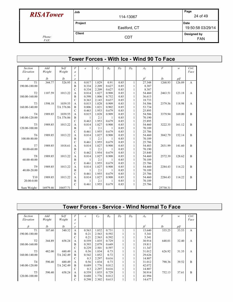
RRIISSAATToowweerr Job 114-13067
Page 24 of 49
Project Eastford, CT
Date 19:50:58 03/29/14
Phone: FAX:
Client CDT
Designed by FAN
Tower Forces - With Ice - Wind 90 To Face
Section Elevation
ft
Add Weight
lb
Self Weight
lb
F a c e
e CF
RR DF
DR
AE
ft2
F
lb
w
plf
Ctrl. Face
T1 190.00-180.00
344.77 526.95 A B C
0.817 0.334 0.334
1.8292.2092.209
0.910.6270.627
0.850.850.85
111
27.3488.3878.387
1268.93 126.89 A
T2 180.00-160.00
1107.59 1013.22 A B C
0.814 0.598 0.363
1.8271.8062.143
0.9080.7520.637
0.850.850.85
111
54.46036.61318.733
2463.51 123.18 A
T3 160.00-140.00
1598.18 1039.55 TA 376.86
A B C
0.815 0.806 0.463
1.8281.8211.953
0.9090.9020.679
0.850.850.85
111
54.50653.73425.895
2379.56 118.98 A
T4 140.00-120.00
1989.85 1039.55 TA 376.86
A B C
0.815 1
0.463
1.8282.1
1.953
0.9091
0.679
0.850.850.85
111
54.50670.19025.895
3379.94 169.00 B
T5 120.00-100.00
1989.85 1013.22 A B C
0.814 1
0.461
1.8272.1
1.955
0.9081
0.679
0.850.850.85
111
54.46070.18925.786
3222.35 161.12 B
T6 100.00-80.00
1989.85 1013.22 A B C
0.814 1
0.461
1.8272.1
1.955
0.9081
0.679
0.850.850.85
111
54.46070.18925.786
3042.79 152.14 B
T7 80.00-60.00
1989.85 1018.61 A B C
0.814 1
0.462
1.8272.1
1.954
0.9081
0.679
0.850.850.85
111
54.48370.19025.840
2831.99 141.60 B
T8 60.00-40.00
1989.85 1013.22 A B C
0.814 1
0.461
1.8272.1
1.955
0.9081
0.679
0.850.850.85
111
54.46070.18925.786
2572.39 128.62 B
T9 40.00-20.00
1989.85 1013.22 A B C
0.814 1
0.461
1.8272.1
1.955
0.9081
0.679
0.850.850.85
111
54.46070.18925.786
2284.43 114.22 B
T10 20.00-0.00
1989.85 1013.22 A B C
0.814 1
0.461
1.8272.1
1.955
0.9081
0.679
0.850.850.85
111
54.46070.18925.786
2284.43 114.22 B
Sum Weight: 16979.46 10457.71 25730.31
Tower Forces - Service - Wind Normal To Face
Section Elevation
ft
Add Weight
lb
Self Weight
lb
F a c e
e CF
RR DF
DR
AE
ft2
F
lb
w
plf
Ctrl. Face
T1 190.00-180.00
107.60 340.32 A B C
0.563 0.21 0.21
1.8322.5632.563
0.7310.5920.592
111
111
15.6405.3415.341
335.25 33.53 A
T2 180.00-160.00
344.89 658.24 A B C
0.559 0.393 0.229
1.8352.0792.501
0.7290.6490.597
111
111
30.91419.81111.347
648.01 32.40 A
T3 160.00-140.00
482.00 680.49 TA 242.49
A B C
0.56 0.542
0.3
1.8341.8522.297
0.730.72
0.616
111
111
31.01229.62614.807
626.92 31.35 A
T4 140.00-120.00
590.40 680.49 TA 242.49
A B C
0.56 0.689
0.3
1.8341.7762.297
0.730.8120.616
111
111
31.01242.07214.807
790.36 39.52 B
T5 120.00-100.00
590.40 658.24 A B C
0.559 0.688 0.298
1.8351.7762.302
0.7290.8120.615
111
111
30.91441.99414.677
752.13 37.61 B
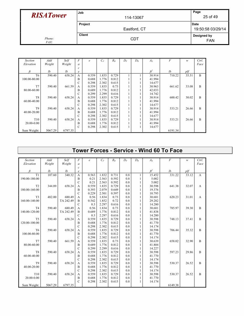
RRIISSAATToowweerr Job 114-13067
Page 25 of 49
Project Eastford, CT
Date 19:50:58 03/29/14
Phone: FAX:
Client CDT
Designed by FAN
Section Elevation
ft
Add Weight
lb
Self Weight
lb
F a c e
e CF
RR DF
DR
AE
ft2
F
lb
w
plf
Ctrl. Face
T6 100.00-80.00
590.40 658.24 A B C
0.559 0.688 0.298
1.8351.7762.302
0.7290.8120.615
111
111
30.91441.99414.677
710.22 35.51 B
T7 80.00-60.00
590.40 661.59 A B C
0.559 0.689 0.299
1.8351.7762.299
0.730.8120.616
111
111
30.96342.03314.742
661.62 33.08 B
T8 60.00-40.00
590.40 658.24 A B C
0.559 0.688 0.298
1.8351.7762.302
0.7290.8120.615
111
111
30.91441.99414.677
600.42 30.02 B
T9 40.00-20.00
590.40 658.24 A B C
0.559 0.688 0.298
1.8351.7762.302
0.7290.8120.615
111
111
30.91441.99414.677
533.21 26.66 B
T10 20.00-0.00
590.40 658.24 A B C
0.559 0.688 0.298
1.8351.7762.302
0.7290.8120.615
111
111
30.91441.99414.677
533.21 26.66 B
Sum Weight: 5067.29 6797.35 6191.34
Tower Forces - Service - Wind 60 To Face
Section Elevation
ft
Add Weight
lb
Self Weight
lb
F a c e
e CF
RR DF
DR
AE
ft2
F
lb
w
plf
Ctrl. Face
T1 190.00-180.00
107.60 340.32 A B C
0.563 0.21 0.21
1.8322.5632.563
0.7310.5920.592
0.80.80.8
111
15.4525.0025.002
331.22 33.12 A
T2 180.00-160.00
344.89 658.24 A B C
0.559 0.393 0.229
1.8352.0792.501
0.7290.6490.597
0.80.80.8
111
30.59819.37610.795
641.38 32.07 A
T3 160.00-140.00
482.00 680.49 TA 242.49
A B C
0.56 0.542
0.3
1.8341.8522.297
0.730.72
0.616
0.80.80.8
111
30.68129.28214.280
620.23 31.01 A
T4 140.00-120.00
590.40 680.49 TA 242.49
A B C
0.56 0.689
0.3
1.8341.7762.297
0.730.8120.616
0.80.80.8
111
30.68141.83814.280
785.97 39.30 B
T5 120.00-100.00
590.40 658.24 A B C
0.559 0.688 0.298
1.8351.7762.302
0.7290.8120.615
0.80.80.8
111
30.59841.77014.174
748.13 37.41 B
T6 100.00-80.00
590.40 658.24 A B C
0.559 0.688 0.298
1.8351.7762.302
0.7290.8120.615
0.80.80.8
111
30.59841.77014.174
706.44 35.32 B
T7 80.00-60.00
590.40 661.59 A B C
0.559 0.689 0.299
1.8351.7762.299
0.730.8120.616
0.80.80.8
111
30.63941.80414.227
658.02 32.90 B
T8 60.00-40.00
590.40 658.24 A B C
0.559 0.688 0.298
1.8351.7762.302
0.7290.8120.615
0.80.80.8
111
30.59841.77014.174
597.23 29.86 B
T9 40.00-20.00
590.40 658.24 A B C
0.559 0.688 0.298
1.8351.7762.302
0.7290.8120.615
0.80.80.8
111
30.59841.77014.174
530.37 26.52 B
T10 20.00-0.00
590.40 658.24 A B C
0.559 0.688 0.298
1.8351.7762.302
0.7290.8120.615
0.80.80.8
111
30.59841.77014.174
530.37 26.52 B
Sum Weight: 5067.29 6797.35 6149.38

RRIISSAATToowweerr Job 114-13067
Page 26 of 49
Project Eastford, CT
Date 19:50:58 03/29/14
Phone: FAX:
Client CDT
Designed by FAN
Tower Forces - Service - Wind 90 To Face
Section Elevation
ft
Add Weight
lb
Self Weight
lb
F a c e
e CF
RR DF
DR
AE
ft2
F
lb
w
plf
Ctrl. Face
T1 190.00-180.00
107.60 340.32 A B C
0.563 0.21 0.21
1.8322.5632.563
0.7310.5920.592
0.850.850.85
111
15.4995.0875.087
332.23 33.22 A
T2 180.00-160.00
344.89 658.24 A B C
0.559 0.393 0.229
1.8352.0792.501
0.7290.6490.597
0.850.850.85
111
30.67719.48510.933
643.04 32.15 A
T3 160.00-140.00
482.00 680.49 TA 242.49
A B C
0.56 0.542
0.3
1.8341.8522.297
0.730.72
0.616
0.850.850.85
111
30.76429.36814.411
621.90 31.10 A
T4 140.00-120.00
590.40 680.49 TA 242.49
A B C
0.56 0.689
0.3
1.8341.7762.297
0.730.8120.616
0.850.850.85
111
30.76441.89614.411
787.07 39.35 B
T5 120.00-100.00
590.40 658.24 A B C
0.559 0.688 0.298
1.8351.7762.302
0.7290.8120.615
0.850.850.85
111
30.67741.82614.300
749.13 37.46 B
T6 100.00-80.00
590.40 658.24 A B C
0.559 0.688 0.298
1.8351.7762.302
0.7290.8120.615
0.850.850.85
111
30.67741.82614.300
707.38 35.37 B
T7 80.00-60.00
590.40 661.59 A B C
0.559 0.689 0.299
1.8351.7762.299
0.730.8120.616
0.850.850.85
111
30.72041.86114.356
658.92 32.95 B
T8 60.00-40.00
590.40 658.24 A B C
0.559 0.688 0.298
1.8351.7762.302
0.7290.8120.615
0.850.850.85
111
30.67741.82614.300
598.03 29.90 B
T9 40.00-20.00
590.40 658.24 A B C
0.559 0.688 0.298
1.8351.7762.302
0.7290.8120.615
0.850.850.85
111
30.67741.82614.300
531.08 26.55 B
T10 20.00-0.00
590.40 658.24 A B C
0.559 0.688 0.298
1.8351.7762.302
0.7290.8120.615
0.850.850.85
111
30.67741.82614.300
531.08 26.55 B
Sum Weight: 5067.29 6797.35 6159.87
Force Totals (Does not include forces on guys)
Load Case
Vertical Forces
lb
Sum of Forces
X lb
Sum of Forces
Z lb
Sum of Torques
lb-ft Leg Weight 3305.16 Bracing Weight 3492.18 Total Member Self-Weight 6797.35 Guy Weight 2622.32 Total Weight 22230.35 Wind 0 deg - No Ice 0.00 -30317.30 266.61Wind 30 deg - No Ice 15113.17 -26176.79 -1173.12Wind 60 deg - No Ice 26150.53 -15098.01 -2297.55Wind 90 deg - No Ice 30226.35 0.00 -2813.87Wind 120 deg - No Ice 26255.55 15158.65 -2581.51Wind 150 deg - No Ice 15113.17 26176.79 -1640.75Wind 180 deg - No Ice 0.00 30196.03 -271.11
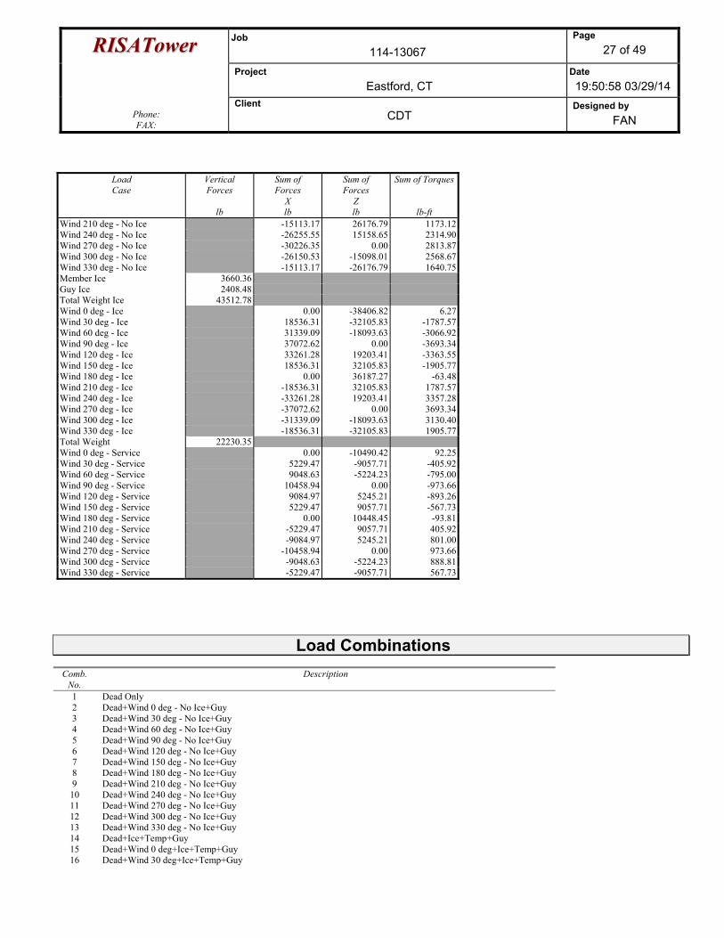
RRIISSAATToowweerr Job 114-13067
Page 27 of 49
Project Eastford, CT
Date 19:50:58 03/29/14
Phone: FAX:
Client CDT
Designed by FAN
Load Case
Vertical Forces
lb
Sum of Forces
X lb
Sum of Forces
Z lb
Sum of Torques
lb-ft Wind 210 deg - No Ice -15113.17 26176.79 1173.12Wind 240 deg - No Ice -26255.55 15158.65 2314.90Wind 270 deg - No Ice -30226.35 0.00 2813.87Wind 300 deg - No Ice -26150.53 -15098.01 2568.67Wind 330 deg - No Ice -15113.17 -26176.79 1640.75Member Ice 3660.36 Guy Ice 2408.48 Total Weight Ice 43512.78 Wind 0 deg - Ice 0.00 -38406.82 6.27Wind 30 deg - Ice 18536.31 -32105.83 -1787.57Wind 60 deg - Ice 31339.09 -18093.63 -3066.92Wind 90 deg - Ice 37072.62 0.00 -3693.34Wind 120 deg - Ice 33261.28 19203.41 -3363.55Wind 150 deg - Ice 18536.31 32105.83 -1905.77Wind 180 deg - Ice 0.00 36187.27 -63.48Wind 210 deg - Ice -18536.31 32105.83 1787.57Wind 240 deg - Ice -33261.28 19203.41 3357.28Wind 270 deg - Ice -37072.62 0.00 3693.34Wind 300 deg - Ice -31339.09 -18093.63 3130.40Wind 330 deg - Ice -18536.31 -32105.83 1905.77Total Weight 22230.35 Wind 0 deg - Service 0.00 -10490.42 92.25Wind 30 deg - Service 5229.47 -9057.71 -405.92Wind 60 deg - Service 9048.63 -5224.23 -795.00Wind 90 deg - Service 10458.94 0.00 -973.66Wind 120 deg - Service 9084.97 5245.21 -893.26Wind 150 deg - Service 5229.47 9057.71 -567.73Wind 180 deg - Service 0.00 10448.45 -93.81Wind 210 deg - Service -5229.47 9057.71 405.92Wind 240 deg - Service -9084.97 5245.21 801.00Wind 270 deg - Service -10458.94 0.00 973.66Wind 300 deg - Service -9048.63 -5224.23 888.81Wind 330 deg - Service -5229.47 -9057.71 567.73
Load Combinations Comb.
No. Description
1 Dead Only 2 Dead+Wind 0 deg - No Ice+Guy 3 Dead+Wind 30 deg - No Ice+Guy 4 Dead+Wind 60 deg - No Ice+Guy 5 Dead+Wind 90 deg - No Ice+Guy 6 Dead+Wind 120 deg - No Ice+Guy 7 Dead+Wind 150 deg - No Ice+Guy 8 Dead+Wind 180 deg - No Ice+Guy 9 Dead+Wind 210 deg - No Ice+Guy 10 Dead+Wind 240 deg - No Ice+Guy 11 Dead+Wind 270 deg - No Ice+Guy 12 Dead+Wind 300 deg - No Ice+Guy 13 Dead+Wind 330 deg - No Ice+Guy 14 Dead+Ice+Temp+Guy 15 Dead+Wind 0 deg+Ice+Temp+Guy 16 Dead+Wind 30 deg+Ice+Temp+Guy
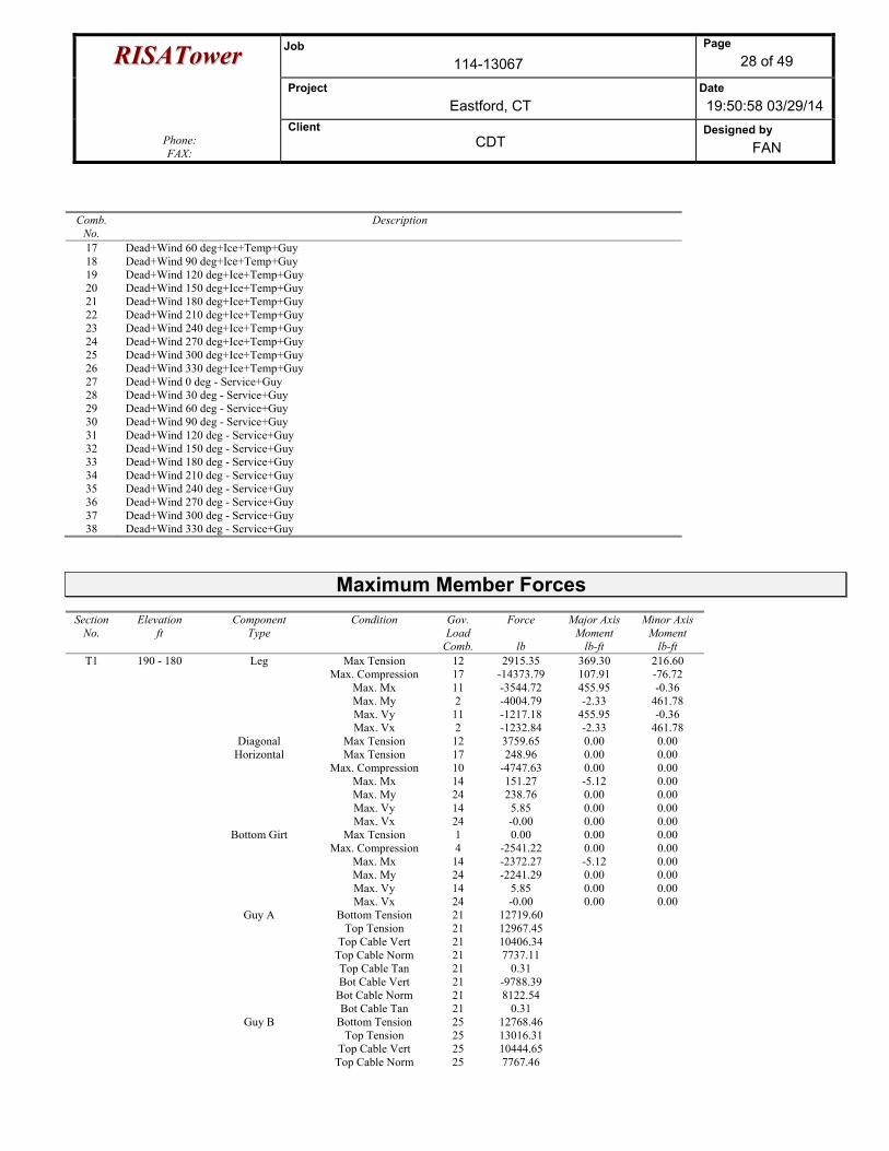
RRIISSAATToowweerr Job 114-13067
Page 28 of 49
Project Eastford, CT
Date 19:50:58 03/29/14
Phone: FAX:
Client CDT
Designed by FAN
Comb. No.
Description
17 Dead+Wind 60 deg+Ice+Temp+Guy 18 Dead+Wind 90 deg+Ice+Temp+Guy 19 Dead+Wind 120 deg+Ice+Temp+Guy 20 Dead+Wind 150 deg+Ice+Temp+Guy 21 Dead+Wind 180 deg+Ice+Temp+Guy 22 Dead+Wind 210 deg+Ice+Temp+Guy 23 Dead+Wind 240 deg+Ice+Temp+Guy 24 Dead+Wind 270 deg+Ice+Temp+Guy 25 Dead+Wind 300 deg+Ice+Temp+Guy 26 Dead+Wind 330 deg+Ice+Temp+Guy 27 Dead+Wind 0 deg - Service+Guy 28 Dead+Wind 30 deg - Service+Guy 29 Dead+Wind 60 deg - Service+Guy 30 Dead+Wind 90 deg - Service+Guy 31 Dead+Wind 120 deg - Service+Guy 32 Dead+Wind 150 deg - Service+Guy 33 Dead+Wind 180 deg - Service+Guy 34 Dead+Wind 210 deg - Service+Guy 35 Dead+Wind 240 deg - Service+Guy 36 Dead+Wind 270 deg - Service+Guy 37 Dead+Wind 300 deg - Service+Guy 38 Dead+Wind 330 deg - Service+Guy
Maximum Member Forces Section
No. Elevation
ft Component
Type Condition Gov.
Load Comb.
Force
lb
Major Axis Moment
lb-ft
Minor Axis Moment
lb-ft T1 190 - 180 Leg Max Tension 12 2915.35 369.30 216.60
Max. Compression 17 -14373.79 107.91 -76.72 Max. Mx 11 -3544.72 455.95 -0.36 Max. My 2 -4004.79 -2.33 461.78 Max. Vy 11 -1217.18 455.95 -0.36 Max. Vx 2 -1232.84 -2.33 461.78 Diagonal Max Tension 12 3759.65 0.00 0.00 Horizontal Max Tension 17 248.96 0.00 0.00 Max. Compression 10 -4747.63 0.00 0.00 Max. Mx 14 151.27 -5.12 0.00 Max. My 24 238.76 0.00 0.00 Max. Vy 14 5.85 0.00 0.00 Max. Vx 24 -0.00 0.00 0.00 Bottom Girt Max Tension 1 0.00 0.00 0.00 Max. Compression 4 -2541.22 0.00 0.00 Max. Mx 14 -2372.27 -5.12 0.00 Max. My 24 -2241.29 0.00 0.00 Max. Vy 14 5.85 0.00 0.00 Max. Vx 24 -0.00 0.00 0.00 Guy A Bottom Tension 21 12719.60 Top Tension 21 12967.45 Top Cable Vert 21 10406.34 Top Cable Norm 21 7737.11 Top Cable Tan 21 0.31 Bot Cable Vert 21 -9788.39 Bot Cable Norm 21 8122.54 Bot Cable Tan 21 0.31 Guy B Bottom Tension 25 12768.46 Top Tension 25 13016.31 Top Cable Vert 25 10444.65 Top Cable Norm 25 7767.46
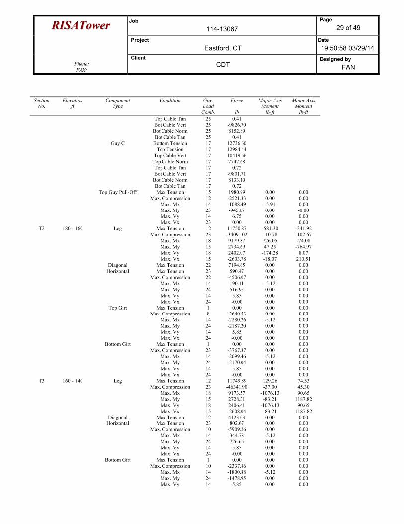
RRIISSAATToowweerr Job 114-13067
Page 29 of 49
Project Eastford, CT
Date 19:50:58 03/29/14
Phone: FAX:
Client CDT
Designed by FAN
Section No.
Elevation ft
Component Type
Condition Gov. Load
Comb.
Force
lb
Major Axis Moment
lb-ft
Minor Axis Moment
lb-ft Top Cable Tan 25 0.41 Bot Cable Vert 25 -9826.70 Bot Cable Norm 25 8152.89 Bot Cable Tan 25 0.41 Guy C Bottom Tension 17 12736.60 Top Tension 17 12984.44 Top Cable Vert 17 10419.66 Top Cable Norm 17 7747.68 Top Cable Tan 17 0.72 Bot Cable Vert 17 -9801.71 Bot Cable Norm 17 8133.10 Bot Cable Tan 17 0.72 Top Guy Pull-Off Max Tension 15 1980.99 0.00 0.00 Max. Compression 12 -2521.33 0.00 0.00 Max. Mx 14 -1088.49 -5.91 0.00 Max. My 23 -945.67 0.00 -0.00 Max. Vy 14 6.75 0.00 0.00 Max. Vx 23 0.00 0.00 0.00
T2 180 - 160 Leg Max Tension 12 11750.87 -581.30 -341.92 Max. Compression 23 -34091.02 110.78 -102.67 Max. Mx 18 9179.87 726.05 -74.08 Max. My 15 2734.69 47.25 -764.97 Max. Vy 18 2402.07 -174.28 8.07 Max. Vx 15 -2603.78 -18.07 210.51 Diagonal Max Tension 22 7194.65 0.00 0.00 Horizontal Max Tension 23 590.47 0.00 0.00 Max. Compression 22 -4506.07 0.00 0.00 Max. Mx 14 190.11 -5.12 0.00 Max. My 24 516.95 0.00 0.00 Max. Vy 14 5.85 0.00 0.00 Max. Vx 24 -0.00 0.00 0.00 Top Girt Max Tension 1 0.00 0.00 0.00 Max. Compression 8 -2640.53 0.00 0.00 Max. Mx 14 -2280.26 -5.12 0.00 Max. My 24 -2187.20 0.00 0.00 Max. Vy 14 5.85 0.00 0.00 Max. Vx 24 -0.00 0.00 0.00 Bottom Girt Max Tension 1 0.00 0.00 0.00 Max. Compression 23 -3767.37 0.00 0.00 Max. Mx 14 -2099.46 -5.12 0.00 Max. My 24 -2170.04 0.00 0.00 Max. Vy 14 5.85 0.00 0.00 Max. Vx 24 -0.00 0.00 0.00
T3 160 - 140 Leg Max Tension 12 11749.89 129.26 74.53 Max. Compression 23 -46341.90 -37.00 45.30 Max. Mx 18 9173.57 -1076.13 90.65 Max. My 15 2728.31 -83.21 1187.82 Max. Vy 18 2406.41 -1076.13 90.65 Max. Vx 15 -2608.04 -83.21 1187.82 Diagonal Max Tension 12 4123.03 0.00 0.00 Horizontal Max Tension 23 802.67 0.00 0.00 Max. Compression 10 -5909.26 0.00 0.00 Max. Mx 14 344.78 -5.12 0.00 Max. My 24 726.66 0.00 0.00 Max. Vy 14 5.85 0.00 0.00 Max. Vx 24 -0.00 0.00 0.00 Bottom Girt Max Tension 1 0.00 0.00 0.00 Max. Compression 10 -2337.86 0.00 0.00 Max. Mx 14 -1800.88 -5.12 0.00 Max. My 24 -1478.95 0.00 0.00 Max. Vy 14 5.85 0.00 0.00

RRIISSAATToowweerr Job 114-13067
Page 30 of 49
Project Eastford, CT
Date 19:50:58 03/29/14
Phone: FAX:
Client CDT
Designed by FAN
Section No.
Elevation ft
Component Type
Condition Gov. Load
Comb.
Force
lb
Major Axis Moment
lb-ft
Minor Axis Moment
lb-ft Max. Vx 24 -0.00 0.00 0.00 Guy A Bottom Tension 21 13306.70 Top Tension 21 13539.74 Top Cable Vert 21 10013.80 Top Cable Norm 21 9113.09 Top Cable Tan 21 5.08 Bot Cable Vert 21 -9439.69 Bot Cable Norm 21 9378.72 Bot Cable Tan 21 6.83 Guy B Bottom Tension 25 13392.77 Top Tension 25 13625.80 Top Cable Vert 25 10076.01 Top Cable Norm 25 9172.58 Top Cable Tan 25 5.43 Bot Cable Vert 25 -9501.91 Bot Cable Norm 25 9438.22 Bot Cable Tan 25 6.48 Guy C Bottom Tension 17 13436.57 Top Tension 17 13669.59 Top Cable Vert 17 10107.64 Top Cable Norm 17 9202.89 Top Cable Tan 17 5.44 Bot Cable Vert 17 -9533.53 Bot Cable Norm 17 9468.53 Bot Cable Tan 17 6.47 Top Guy Pull-Off Max Tension 17 1281.64 0.00 0.00 Max. Compression 15 -5134.06 0.00 0.00 Max. Mx 14 -2075.14 -8.96 0.00 Max. My 24 -1830.72 0.00 0.00 Max. Vy 14 10.24 0.00 0.00 Max. Vx 24 -0.00 0.00 0.00 Torque Arm Top Max Tension 23 12229.75 0.00 0.00 Max. Compression 1 0.00 0.00 0.00 Max. Mx 15 12158.49 -15.95 0.00 Max. My 23 6439.79 0.00 -0.14 Max. Vy 15 13.43 0.00 0.00 Max. Vx 23 0.12 0.00 0.00 Torque Arm Bottom Max Tension 15 2771.94 0.00 0.00 Max. Compression 25 -8945.14 0.00 0.00 Max. Mx 17 -8786.15 -11.66 0.00 Max. My 24 -4550.64 0.00 -0.00 Max. Vy 17 13.33 0.00 0.00 Max. Vx 24 0.00 0.00 0.00
T4 140 - 120 Leg Max Tension 1 0.00 0.00 0.00 Max. Compression 15 -63031.44 71.33 957.61 Max. Mx 19 -15690.15 -1185.42 -504.39 Max. My 15 -15381.51 -106.48 1191.82 Max. Vy 18 -2399.42 -1139.83 -32.50 Max. Vx 15 2394.44 -106.48 1191.82 Diagonal Max Tension 8 3873.47 0.00 0.00 Horizontal Max Tension 15 1091.74 0.00 0.00 Max. Compression 2 -4359.64 0.00 0.00 Max. Mx 14 456.41 -5.12 0.00 Max. My 24 964.21 0.00 0.00 Max. Vy 14 5.85 0.00 0.00 Max. Vx 24 -0.00 0.00 0.00 Top Girt Max Tension 1 0.00 0.00 0.00 Max. Compression 28 -1956.00 0.00 0.00 Max. Mx 14 -1789.95 -5.12 0.00 Max. My 24 -1544.97 0.00 0.00 Max. Vy 14 5.85 0.00 0.00
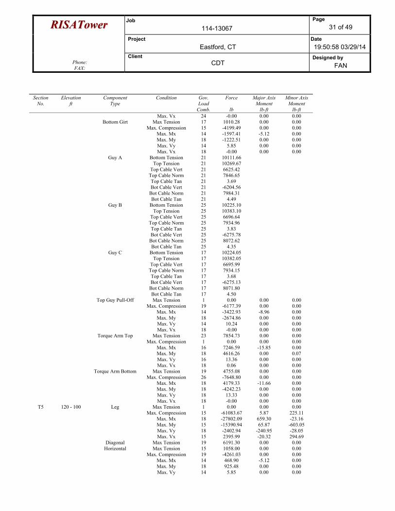
RRIISSAATToowweerr Job 114-13067
Page 31 of 49
Project Eastford, CT
Date 19:50:58 03/29/14
Phone: FAX:
Client CDT
Designed by FAN
Section No.
Elevation ft
Component Type
Condition Gov. Load
Comb.
Force
lb
Major Axis Moment
lb-ft
Minor Axis Moment
lb-ft Max. Vx 24 -0.00 0.00 0.00 Bottom Girt Max Tension 17 1010.28 0.00 0.00 Max. Compression 15 -4199.49 0.00 0.00 Max. Mx 14 -1597.41 -5.12 0.00 Max. My 18 -1222.51 0.00 0.00 Max. Vy 14 5.85 0.00 0.00 Max. Vx 18 -0.00 0.00 0.00 Guy A Bottom Tension 21 10111.66 Top Tension 21 10269.67 Top Cable Vert 21 6625.42 Top Cable Norm 21 7846.65 Top Cable Tan 21 3.69 Bot Cable Vert 21 -6204.56 Bot Cable Norm 21 7984.31 Bot Cable Tan 21 4.49 Guy B Bottom Tension 25 10225.10 Top Tension 25 10383.10 Top Cable Vert 25 6696.64 Top Cable Norm 25 7934.96 Top Cable Tan 25 3.83 Bot Cable Vert 25 -6275.78 Bot Cable Norm 25 8072.62 Bot Cable Tan 25 4.35 Guy C Bottom Tension 17 10224.05 Top Tension 17 10382.05 Top Cable Vert 17 6695.99 Top Cable Norm 17 7934.15 Top Cable Tan 17 3.68 Bot Cable Vert 17 -6275.13 Bot Cable Norm 17 8071.80 Bot Cable Tan 17 4.50 Top Guy Pull-Off Max Tension 1 0.00 0.00 0.00 Max. Compression 19 -6177.39 0.00 0.00 Max. Mx 14 -3422.93 -8.96 0.00 Max. My 18 -2674.86 0.00 0.00 Max. Vy 14 10.24 0.00 0.00 Max. Vx 18 -0.00 0.00 0.00 Torque Arm Top Max Tension 23 7854.73 0.00 0.00 Max. Compression 1 0.00 0.00 0.00 Max. Mx 16 7246.59 -15.85 0.00 Max. My 18 4616.26 0.00 0.07 Max. Vy 16 13.36 0.00 0.00 Max. Vx 18 0.06 0.00 0.00 Torque Arm Bottom Max Tension 19 4755.08 0.00 0.00 Max. Compression 26 -7648.80 0.00 0.00 Max. Mx 18 4179.33 -11.66 0.00 Max. My 18 -4242.23 0.00 0.00 Max. Vy 18 13.33 0.00 0.00 Max. Vx 18 -0.00 0.00 0.00
T5 120 - 100 Leg Max Tension 1 0.00 0.00 0.00 Max. Compression 15 -61083.67 5.87 225.11 Max. Mx 18 -27802.09 659.30 -23.16 Max. My 15 -15390.94 65.87 -603.05 Max. Vy 18 -2402.94 -240.95 -28.05 Max. Vx 15 2395.99 -20.32 294.69 Diagonal Max Tension 19 6191.30 0.00 0.00 Horizontal Max Tension 15 1058.00 0.00 0.00 Max. Compression 19 -4261.03 0.00 0.00 Max. Mx 14 468.90 -5.12 0.00 Max. My 18 925.48 0.00 0.00 Max. Vy 14 5.85 0.00 0.00
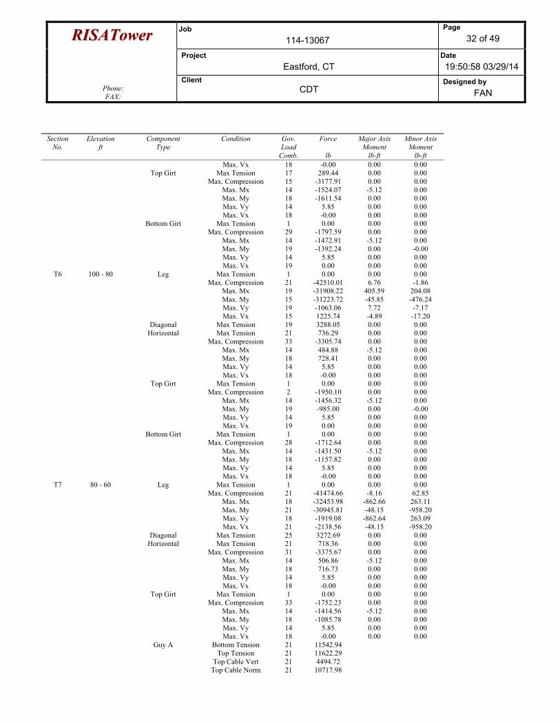
RRIISSAATToowweerr Job 114-13067
Page 32 of 49
Project Eastford, CT
Date 19:50:58 03/29/14
Phone: FAX:
Client CDT
Designed by FAN
Section No.
Elevation ft
Component Type
Condition Gov. Load
Comb.
Force
lb
Major Axis Moment
lb-ft
Minor Axis Moment
lb-ft Max. Vx 18 -0.00 0.00 0.00 Top Girt Max Tension 17 289.44 0.00 0.00 Max. Compression 15 -3177.91 0.00 0.00 Max. Mx 14 -1524.07 -5.12 0.00 Max. My 18 -1611.54 0.00 0.00 Max. Vy 14 5.85 0.00 0.00 Max. Vx 18 -0.00 0.00 0.00 Bottom Girt Max Tension 1 0.00 0.00 0.00 Max. Compression 29 -1797.59 0.00 0.00 Max. Mx 14 -1472.91 -5.12 0.00 Max. My 19 -1392.24 0.00 -0.00 Max. Vy 14 5.85 0.00 0.00 Max. Vx 19 0.00 0.00 0.00
T6 100 - 80 Leg Max Tension 1 0.00 0.00 0.00 Max. Compression 21 -42510.01 6.76 -1.86 Max. Mx 19 -31908.22 405.59 204.08 Max. My 15 -31223.72 -45.85 -476.24 Max. Vy 19 -1063.06 7.72 -7.17 Max. Vx 15 1225.74 -4.89 -17.20 Diagonal Max Tension 19 3288.05 0.00 0.00 Horizontal Max Tension 21 736.29 0.00 0.00 Max. Compression 33 -3305.74 0.00 0.00 Max. Mx 14 484.88 -5.12 0.00 Max. My 18 728.41 0.00 0.00 Max. Vy 14 5.85 0.00 0.00 Max. Vx 18 -0.00 0.00 0.00 Top Girt Max Tension 1 0.00 0.00 0.00 Max. Compression 2 -1950.10 0.00 0.00 Max. Mx 14 -1456.32 -5.12 0.00 Max. My 19 -985.00 0.00 -0.00 Max. Vy 14 5.85 0.00 0.00 Max. Vx 19 0.00 0.00 0.00 Bottom Girt Max Tension 1 0.00 0.00 0.00 Max. Compression 28 -1712.64 0.00 0.00 Max. Mx 14 -1431.50 -5.12 0.00 Max. My 18 -1157.82 0.00 0.00 Max. Vy 14 5.85 0.00 0.00 Max. Vx 18 -0.00 0.00 0.00
T7 80 - 60 Leg Max Tension 1 0.00 0.00 0.00 Max. Compression 21 -41474.66 -8.16 62.85 Max. Mx 18 -32453.98 -862.66 263.11 Max. My 21 -30945.81 -48.15 -958.20 Max. Vy 18 -1919.08 -862.64 263.09 Max. Vx 21 -2138.56 -48.15 -958.20 Diagonal Max Tension 25 3272.69 0.00 0.00 Horizontal Max Tension 21 718.36 0.00 0.00 Max. Compression 31 -3375.67 0.00 0.00 Max. Mx 14 506.86 -5.12 0.00 Max. My 18 716.73 0.00 0.00 Max. Vy 14 5.85 0.00 0.00 Max. Vx 18 -0.00 0.00 0.00 Top Girt Max Tension 1 0.00 0.00 0.00 Max. Compression 33 -1752.23 0.00 0.00 Max. Mx 14 -1414.56 -5.12 0.00 Max. My 18 -1085.78 0.00 0.00 Max. Vy 14 5.85 0.00 0.00 Max. Vx 18 -0.00 0.00 0.00 Guy A Bottom Tension 21 11542.94 Top Tension 21 11622.29 Top Cable Vert 21 4494.72 Top Cable Norm 21 10717.98
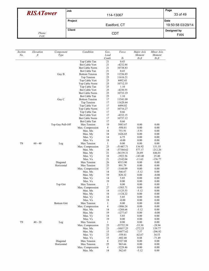
RRIISSAATToowweerr Job 114-13067
Page 33 of 49
Project Eastford, CT
Date 19:50:58 03/29/14
Phone: FAX:
Client CDT
Designed by FAN
Section No.
Elevation ft
Component Type
Condition Gov. Load
Comb.
Force
lb
Major Axis Moment
lb-ft
Minor Axis Moment
lb-ft Top Cable Tan 21 0.43 Bot Cable Vert 21 -4232.84 Bot Cable Norm 21 10738.83 Bot Cable Tan 21 0.43 Guy B Bottom Tension 25 11536.85 Top Tension 25 11616.21 Top Cable Vert 25 4492.43 Top Cable Norm 25 10712.35 Top Cable Tan 25 1.10 Bot Cable Vert 25 -4230.55 Bot Cable Norm 25 10733.19 Bot Cable Tan 25 1.10 Guy C Bottom Tension 17 11541.09 Top Tension 17 11620.44 Top Cable Vert 17 4494.02 Top Cable Norm 17 10716.27 Top Cable Tan 17 0.66 Bot Cable Vert 17 -4232.15 Bot Cable Norm 17 10737.12 Bot Cable Tan 17 0.66 Top Guy Pull-Off Max Tension 19 3883.67 0.00 0.00 Max. Compression 4 -950.81 0.00 0.00 Max. Mx 14 751.91 -5.91 0.00 Max. My 18 1626.65 0.00 0.00 Max. Vy 14 6.75 0.00 0.00 Max. Vx 18 -0.00 0.00 0.00
T8 60 - 40 Leg Max Tension 1 0.00 0.00 0.00 Max. Compression 25 -51487.71 136.92 131.55 Max. Mx 18 -37344.62 577.17 -212.26 Max. My 21 -36139.31 24.89 646.01 Max. Vy 18 -1922.56 -143.40 25.40 Max. Vx 21 -2142.04 -11.63 -156.77 Diagonal Max Tension 26 4513.90 0.00 0.00 Horizontal Max Tension 25 891.79 0.00 0.00 Max. Compression 37 -3160.09 0.00 0.00 Max. Mx 14 546.67 -5.12 0.00 Max. My 19 828.32 0.00 -0.00 Max. Vy 14 5.85 0.00 0.00 Max. Vx 19 0.00 0.00 0.00 Top Girt Max Tension 1 0.00 0.00 0.00 Max. Compression 27 -1583.71 0.00 0.00 Max. Mx 14 -1125.53 -5.12 0.00 Max. My 18 -1124.22 0.00 0.00 Max. Vy 14 5.85 0.00 0.00 Max. Vx 18 -0.00 0.00 0.00 Bottom Girt Max Tension 1 0.00 0.00 0.00 Max. Compression 4 -1806.24 0.00 0.00 Max. Mx 14 -1268.66 -5.12 0.00 Max. My 19 -1277.67 0.00 -0.00 Max. Vy 14 5.85 0.00 0.00 Max. Vx 19 0.00 0.00 0.00
T9 40 - 20 Leg Max Tension 1 0.00 0.00 0.00 Max. Compression 25 -55752.39 -53.30 -28.94 Max. Mx 23 -18837.25 -272.25 139.77 Max. My 15 -18877.62 7.57 -296.92 Max. Vy 23 -559.81 -62.67 34.53 Max. Vx 15 -602.40 0.88 -71.49 Diagonal Max Tension 6 2527.88 0.00 0.00 Horizontal Max Tension 25 965.66 0.00 0.00 Max. Compression 4 -3229.46 0.00 0.00 Max. Mx 14 562.65 -5.12 0.00
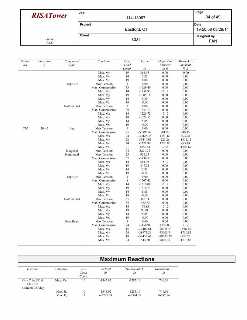
RRIISSAATToowweerr Job 114-13067
Page 34 of 49
Project Eastford, CT
Date 19:50:58 03/29/14
Phone: FAX:
Client CDT
Designed by FAN
Section No.
Elevation ft
Component Type
Condition Gov. Load
Comb.
Force
lb
Major Axis Moment
lb-ft
Minor Axis Moment
lb-ft Max. My 19 861.55 0.00 -0.00 Max. Vy 14 5.85 0.00 0.00 Max. Vx 19 0.00 0.00 0.00 Top Girt Max Tension 1 0.00 0.00 0.00 Max. Compression 33 -1629.40 0.00 0.00 Max. Mx 14 -1251.93 -5.12 0.00 Max. My 19 -1085.18 0.00 0.00 Max. Vy 14 5.85 0.00 0.00 Max. Vx 19 -0.00 0.00 0.00 Bottom Girt Max Tension 1 0.00 0.00 0.00 Max. Compression 29 -1634.14 0.00 0.00 Max. Mx 14 -1226.72 -5.12 0.00 Max. My 19 -1024.55 0.00 0.00 Max. Vy 14 5.85 0.00 0.00 Max. Vx 19 -0.00 0.00 0.00
T10 20 - 0 Leg Max Tension 1 0.00 0.00 0.00 Max. Compression 25 -53995.42 -81.98 -40.35 Max. Mx 24 -39428.38 1250.80 493.78 Max. My 22 -39410.02 222.26 -1312.12 Max. Vy 24 -3221.90 1250.80 493.78 Max. Vx 21 3456.44 -2.56 -1308.67 Diagonal Max Tension 24 3291.74 0.00 0.00 Horizontal Max Tension 25 935.23 0.00 0.00 Max. Compression 37 -3136.77 0.00 0.00 Max. Mx 14 581.95 -5.12 0.00 Max. My 19 847.21 0.00 0.00 Max. Vy 14 5.85 0.00 0.00 Max. Vx 19 -0.00 0.00 0.00 Top Girt Max Tension 1 0.00 0.00 0.00 Max. Compression 8 -1767.45 0.00 0.00 Max. Mx 14 -1210.08 -5.12 0.00 Max. My 19 -1218.77 0.00 0.00 Max. Vy 14 5.85 0.00 0.00 Max. Vx 19 -0.00 0.00 0.00 Bottom Girt Max Tension 25 365.71 0.00 0.00 Max. Compression 35 -422.82 0.00 0.00 Max. Mx 14 -98.83 -5.12 0.00 Max. My 19 90.81 0.00 0.00 Max. Vy 14 5.85 0.00 0.00 Max. Vx 19 -0.00 0.00 0.00 Base Beam Max Tension 1 0.00 0.00 0.00 Max. Compression 24 -3450.96 1329.82 2.19 Max. Mx 15 -39402.61 -78485.67 1498.24 Max. My 24 -38973.26 -78003.91 -1710.83 Max. Vy 18 -39435.42 -78373.29 -853.28 Max. Vx 24 -844.80 -78003.91 -1710.83
Maximum Reactions
Location Condition Gov. Load
Comb.
Vertical lb
Horizontal, X lb
Horizontal, Z lb
Guy C @ 150 ft Elev 0 ft
Azimuth 240 deg
Max. Vert 10 -1345.92 -1285.16 741.56
Max. Hx 10 -1345.92 -1285.16 741.56 Max. Hz 17 -45285.09 -46364.39 26782.14
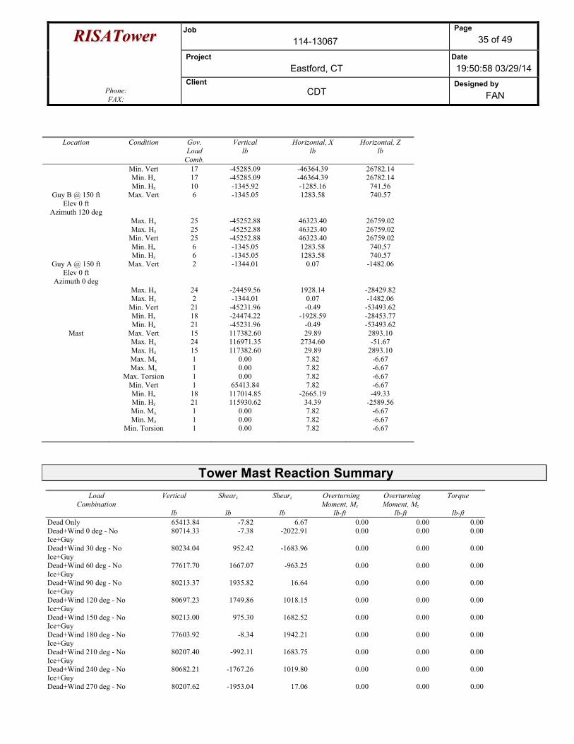
RRIISSAATToowweerr Job 114-13067
Page 35 of 49
Project Eastford, CT
Date 19:50:58 03/29/14
Phone: FAX:
Client CDT
Designed by FAN
Location Condition Gov. Load
Comb.
Vertical lb
Horizontal, X lb
Horizontal, Z lb
Min. Vert 17 -45285.09 -46364.39 26782.14 Min. Hx 17 -45285.09 -46364.39 26782.14 Min. Hz 10 -1345.92 -1285.16 741.56
Guy B @ 150 ft Elev 0 ft
Azimuth 120 deg
Max. Vert 6 -1345.05 1283.58 740.57
Max. Hx 25 -45252.88 46323.40 26759.02 Max. Hz 25 -45252.88 46323.40 26759.02 Min. Vert 25 -45252.88 46323.40 26759.02 Min. Hx 6 -1345.05 1283.58 740.57 Min. Hz 6 -1345.05 1283.58 740.57
Guy A @ 150 ft Elev 0 ft
Azimuth 0 deg
Max. Vert 2 -1344.01 0.07 -1482.06
Max. Hx 24 -24459.56 1928.14 -28429.82 Max. Hz 2 -1344.01 0.07 -1482.06 Min. Vert 21 -45231.96 -0.49 -53493.62 Min. Hx 18 -24474.22 -1928.59 -28453.77 Min. Hz 21 -45231.96 -0.49 -53493.62
Mast Max. Vert 15 117382.60 29.89 2893.10 Max. Hx 24 116971.35 2734.60 -51.67 Max. Hz 15 117382.60 29.89 2893.10 Max. Mx 1 0.00 7.82 -6.67 Max. Mz 1 0.00 7.82 -6.67 Max. Torsion 1 0.00 7.82 -6.67 Min. Vert 1 65413.84 7.82 -6.67 Min. Hx 18 117014.85 -2665.19 -49.33 Min. Hz 21 115930.62 34.39 -2589.56 Min. Mx 1 0.00 7.82 -6.67 Min. Mz 1 0.00 7.82 -6.67 Min. Torsion 1 0.00 7.82 -6.67
Tower Mast Reaction Summary
Load Combination
Vertical
lb
Shearx
lb
Shearz
lb
Overturning Moment, Mx
lb-ft
Overturning Moment, Mz
lb-ft
Torque
lb-ft Dead Only 65413.84 -7.82 6.67 0.00 0.00 0.00Dead+Wind 0 deg - No Ice+Guy
80714.33 -7.38 -2022.91 0.00 0.00 0.00
Dead+Wind 30 deg - No Ice+Guy
80234.04 952.42 -1683.96 0.00 0.00 0.00
Dead+Wind 60 deg - No Ice+Guy
77617.70 1667.07 -963.25 0.00 0.00 0.00
Dead+Wind 90 deg - No Ice+Guy
80213.37 1935.82 16.64 0.00 0.00 0.00
Dead+Wind 120 deg - No Ice+Guy
80697.23 1749.86 1018.15 0.00 0.00 0.00
Dead+Wind 150 deg - No Ice+Guy
80213.00 975.30 1682.52 0.00 0.00 0.00
Dead+Wind 180 deg - No Ice+Guy
77603.92 -8.34 1942.21 0.00 0.00 0.00
Dead+Wind 210 deg - No Ice+Guy
80207.40 -992.11 1683.75 0.00 0.00 0.00
Dead+Wind 240 deg - No Ice+Guy
80682.21 -1767.26 1019.80 0.00 0.00 0.00
Dead+Wind 270 deg - No 80207.62 -1953.04 17.06 0.00 0.00 0.00
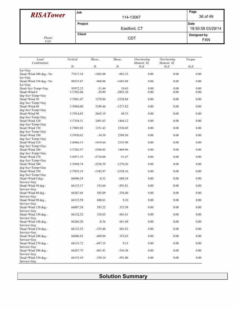
RRIISSAATToowweerr Job 114-13067
Page 36 of 49
Project Eastford, CT
Date 19:50:58 03/29/14
Phone: FAX:
Client CDT
Designed by FAN
Load Combination
Vertical
lb
Shearx
lb
Shearz
lb
Overturning Moment, Mx
lb-ft
Overturning Moment, Mz
lb-ft
Torque
lb-ft Ice+Guy Dead+Wind 300 deg - No Ice+Guy
77617.18 -1683.80 -963.23 0.00 0.00 0.00
Dead+Wind 330 deg - No Ice+Guy
80233.87 -968.06 -1683.88 0.00 0.00 0.00
Dead+Ice+Temp+Guy 93972.23 -31.44 19.63 0.00 0.00 0.00Dead+Wind 0 deg+Ice+Temp+Guy
117382.60 -29.89 -2893.10 0.00 0.00 0.00
Dead+Wind 30 deg+Ice+Temp+Guy
117041.47 1279.84 -2338.84 0.00 0.00 0.00
Dead+Wind 60 deg+Ice+Temp+Guy
115968.00 2189.44 -1271.82 0.00 0.00 0.00
Dead+Wind 90 deg+Ice+Temp+Guy
117014.85 2665.19 49.33 0.00 0.00 0.00
Dead+Wind 120 deg+Ice+Temp+Guy
117354.31 2491.63 1464.12 0.00 0.00 0.00
Dead+Wind 150 deg+Ice+Temp+Guy
117003.02 1351.43 2330.85 0.00 0.00 0.00
Dead+Wind 180 deg+Ice+Temp+Guy
115930.62 -34.39 2589.56 0.00 0.00 0.00
Dead+Wind 210 deg+Ice+Temp+Guy
116966.15 -1419.64 2335.90 0.00 0.00 0.00
Dead+Wind 240 deg+Ice+Temp+Guy
117282.57 -2560.82 1469.96 0.00 0.00 0.00
Dead+Wind 270 deg+Ice+Temp+Guy
116971.35 -2734.60 51.67 0.00 0.00 0.00
Dead+Wind 300 deg+Ice+Temp+Guy
115949.74 -2256.59 -1270.26 0.00 0.00 0.00
Dead+Wind 330 deg+Ice+Temp+Guy
117035.19 -1342.97 -2338.16 0.00 0.00 0.00
Dead+Wind 0 deg - Service+Guy
66006.24 -8.32 -688.24 0.00 0.00 0.00
Dead+Wind 30 deg - Service+Guy
66133.17 333.64 -591.81 0.00 0.00 0.00
Dead+Wind 60 deg - Service+Guy
66267.64 585.09 -336.40 0.00 0.00 0.00
Dead+Wind 90 deg - Service+Guy
66133.59 680.61 9.10 0.00 0.00 0.00
Dead+Wind 120 deg - Service+Guy
66007.38 593.22 353.58 0.00 0.00 0.00
Dead+Wind 150 deg - Service+Guy
66132.32 338.65 601.61 0.00 0.00 0.00
Dead+Wind 180 deg - Service+Guy
66266.20 -8.36 691.69 0.00 0.00 0.00
Dead+Wind 210 deg - Service+Guy
66132.52 -355.40 601.63 0.00 0.00 0.00
Dead+Wind 240 deg - Service+Guy
66006.83 -609.94 353.65 0.00 0.00 0.00
Dead+Wind 270 deg - Service+Guy
66133.72 -697.35 9.15 0.00 0.00 0.00
Dead+Wind 300 deg - Service+Guy
66267.75 -601.81 -336.38 0.00 0.00 0.00
Dead+Wind 330 deg - Service+Guy
66133.10 -350.34 -591.80 0.00 0.00 0.00
Solution Summary
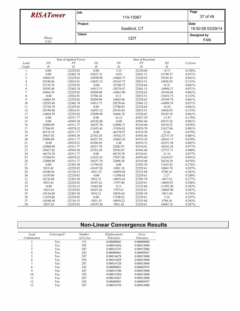
RRIISSAATToowweerr Job 114-13067
Page 37 of 49
Project Eastford, CT
Date 19:50:58 03/29/14
Phone: FAX:
Client CDT
Designed by FAN
Load
Comb.
Sum of Applied Forces Sum of Reactions % Error PX
lb PY lb
PZ lb
PX lb
PY lb
PZ lb
1 0.00 -22229.82 0.00 3.35 22150.48 -4.73 0.358% 2 0.00 -22442.74 -33827.51 -0.02 22441.31 33798.57 0.071% 3 16864.39 -22229.82 -29209.98 -16866.73 22228.63 29185.45 0.061% 4 29190.46 -22016.91 -16853.12 -29143.75 22015.51 16826.92 0.133% 5 33728.78 -22229.82 -0.00 -33708.75 22228.64 14.31 0.061% 6 29295.48 -22442.74 16913.75 -29270.47 22441.31 -16899.27 0.071% 7 16864.39 -22229.82 29209.98 -16841.90 22228.63 -29199.68 0.061% 8 -0.00 -22016.91 33706.24 0.11 22015.51 -33652.73 0.133% 9 -16864.39 -22229.82 29209.98 16842.06 22228.63 -29199.79 0.061% 10 -29295.48 -22442.74 16913.75 29270.64 22441.32 -16899.39 0.071% 11 -33728.78 -22229.82 0.00 33708.85 22228.64 14.24 0.061% 12 -29190.46 -22016.91 -16853.12 29143.84 22015.51 16826.85 0.133% 13 -16864.39 -22229.82 -29209.98 16866.70 22228.62 29185.38 0.061% 14 0.00 -43511.77 0.00 16.12 43437.29 -13.47 0.178% 15 0.00 -43945.30 -45526.40 -0.08 43943.46 45475.26 0.081% 16 22088.09 -43511.77 -38257.70 -22096.71 43510.40 38210.22 0.078% 17 37504.83 -43078.23 -21653.43 -37456.01 43076.70 21627.06 0.091% 18 44176.18 -43511.77 -0.00 -44139.07 43510.39 31.66 0.079% 19 39427.02 -43945.30 22763.20 -39382.57 43943.46 -22737.35 0.081% 20 22088.09 -43511.77 38257.70 -22042.38 43510.39 -38241.17 0.078% 21 -0.00 -43078.23 43306.85 2.48 43076.72 -43251.58 0.091% 22 -22088.09 -43511.77 38257.70 22042.97 43510.41 -38241.54 0.077% 23 -39427.02 -43945.30 22763.20 39383.07 43943.48 -22737.71 0.080% 24 -44176.18 -43511.77 0.00 44139.70 43510.41 31.16 0.077% 25 -37504.83 -43078.23 -21653.43 37457.20 43076.69 21624.97 0.091% 26 -22088.09 -43511.77 -38257.70 22096.56 43510.40 38210.29 0.078% 27 0.00 -22303.50 -11705.02 0.06 22303.39 11635.43 0.276% 28 5835.43 -22229.82 -10107.26 -5801.18 22229.61 10043.78 0.287% 29 10100.50 -22156.15 -5831.53 -10039.04 22155.84 5796.18 0.283% 30 11670.86 -22229.82 -0.00 -11598.63 22229.61 2.27 0.288% 31 10136.84 -22303.50 5852.51 -10076.43 22303.39 -5817.61 0.277% 32 5835.43 -22229.82 10107.26 -5797.40 22229.61 -10045.87 0.288% 33 -0.00 -22156.15 11663.06 0.11 22155.84 -11592.20 0.283% 34 -5835.43 -22229.82 10107.26 5797.61 22229.61 -10045.90 0.287% 35 -10136.84 -22303.50 5852.51 10076.65 22303.39 -5817.66 0.276% 36 -11670.86 -22229.82 0.00 11598.83 22229.61 2.24 0.287% 37 -10100.50 -22156.15 -5831.53 10039.22 22155.84 5796.16 0.283% 38 -5835.43 -22229.82 -10107.26 5801.34 22229.61 10043.76 0.287%
Non-Linear Convergence Results
Load Combination
Converged? Number of Cycles
Displacement Tolerance
Force Tolerance
1 Yes 121 0.00000001 0.00000000 2 Yes 295 0.00014456 0.00015000 3 Yes 287 0.00014747 0.00015000 4 Yes 242 0.00000001 0.00005967 5 Yes 287 0.00014678 0.00015000 6 Yes 295 0.00014429 0.00015000 7 Yes 287 0.00014720 0.00015000 8 Yes 242 0.00000001 0.00005955 9 Yes 287 0.00014700 0.00015000 10 Yes 295 0.00014384 0.00015000 11 Yes 287 0.00014667 0.00015000 12 Yes 242 0.00000001 0.00005957 13 Yes 287 0.00014756 0.00015000
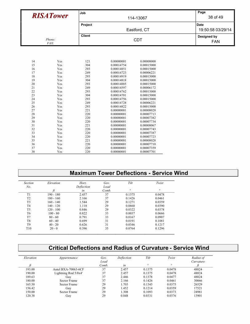
RRIISSAATToowweerr Job 114-13067
Page 38 of 49
Project Eastford, CT
Date 19:50:58 03/29/14
Phone: FAX:
Client CDT
Designed by FAN
14 Yes 121 0.00000001 0.00000000 15 Yes 304 0.00014754 0.00015000 16 Yes 293 0.00014851 0.00015000 17 Yes 249 0.00014723 0.00006221 18 Yes 293 0.00014919 0.00015000 19 Yes 304 0.00014818 0.00015000 20 Yes 293 0.00014885 0.00015000 21 Yes 249 0.00014597 0.00006172 22 Yes 293 0.00014762 0.00015000 23 Yes 304 0.00014701 0.00015000 24 Yes 293 0.00014756 0.00015000 25 Yes 249 0.00014728 0.00006221 26 Yes 293 0.00014822 0.00015000 27 Yes 221 0.00000001 0.00008020 28 Yes 220 0.00000001 0.00007713 29 Yes 220 0.00000001 0.00007382 30 Yes 220 0.00000001 0.00007734 31 Yes 221 0.00000001 0.00008067 32 Yes 220 0.00000001 0.00007743 33 Yes 220 0.00000001 0.00007387 34 Yes 220 0.00000001 0.00007723 35 Yes 221 0.00000001 0.00008028 36 Yes 220 0.00000001 0.00007710 37 Yes 220 0.00000001 0.00007359 38 Yes 220 0.00000001 0.00007701
Maximum Tower Deflections - Service Wind
Section No.
Elevation
ft
Horz. Deflection
in
Gov. Load
Comb.
Tilt °
Twist °
T1 190 - 180 2.457 37 0.1375 0.0478 T2 180 - 160 2.166 37 0.1426 0.0461 T3 160 - 140 1.544 29 0.1271 0.0359 T4 140 - 120 1.118 29 0.0860 0.0390 T5 120 - 100 0.846 29 0.0322 0.0378 T6 100 - 80 0.822 33 0.0037 0.0666 T7 80 - 60 0.791 33 0.0167 0.0907 T8 60 - 40 0.699 31 0.0191 0.1081 T9 40 - 20 0.626 31 0.0346 0.1217
T10 20 - 0 0.396 35 0.0764 0.1296
Critical Deflections and Radius of Curvature - Service Wind
Elevation
ft
Appurtenance Gov. Load
Comb.
Deflection
in
Tilt °
Twist °
Radius of Curvature
ft 193.00 Antel BXA-70063-6CF 37 2.457 0.1375 0.0478 48824 190.00 Lightning Rod 5/8x4' 37 2.457 0.1375 0.0478 48824 189.63 Guy 37 2.446 0.1378 0.0477 48824 180.00 Sector Frame 37 2.166 0.1426 0.0461 30066 165.50 Sector Frame 29 1.703 0.1345 0.0375 26529 156.42 Guy 29 1.452 0.1214 0.0359 17521 150.00 Sector Frame 29 1.308 0.1093 0.0373 24981 120.38 Guy 29 0.848 0.0331 0.0376 13901
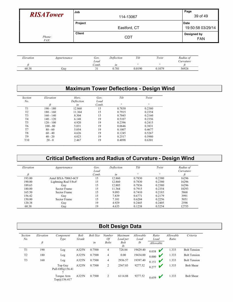
RRIISSAATToowweerr Job 114-13067
Page 39 of 49
Project Eastford, CT
Date 19:50:58 03/29/14
Phone: FAX:
Client CDT
Designed by FAN
Elevation
ft
Appurtenance Gov. Load
Comb.
Deflection
in
Tilt °
Twist °
Radius of Curvature
ft 60.38 Guy 31 0.701 0.0190 0.1079 56924
Maximum Tower Deflections - Design Wind
Section No.
Elevation
ft
Horz. Deflection
in
Gov. Load
Comb.
Tilt °
Twist °
T1 190 - 180 12.860 15 0.7830 0.2380 T2 180 - 160 11.364 15 0.7915 0.2354 T3 160 - 140 8.304 15 0.7045 0.2160 T4 140 - 120 6.148 19 0.5107 0.2356 T5 120 - 100 4.920 19 0.2396 0.2415 T6 100 - 80 5.031 19 0.0646 0.3831 T7 80 - 60 5.054 19 0.1007 0.4677 T8 60 - 40 4.626 19 0.1245 0.5267 T9 40 - 20 4.023 19 0.2517 0.5980
T10 20 - 0 2.467 19 0.4898 0.6301
Critical Deflections and Radius of Curvature - Design Wind
Elevation
ft
Appurtenance Gov. Load
Comb.
Deflection
in
Tilt °
Twist °
Radius of Curvature
ft 193.00 Antel BXA-70063-6CF 15 12.860 0.7830 0.2380 16296 190.00 Lightning Rod 5/8x4' 15 12.860 0.7830 0.2380 16296 189.63 Guy 15 12.805 0.7836 0.2380 16296 180.00 Sector Frame 15 11.364 0.7915 0.2354 10293 165.50 Sector Frame 15 9.093 0.7410 0.2183 5868 156.42 Guy 15 7.839 0.6771 0.2179 3991 150.00 Sector Frame 15 7.101 0.6204 0.2256 5051 120.38 Guy 19 4.929 0.2445 0.2405 2598 60.38 Guy 19 4.635 0.1238 0.5254 12755
Bolt Design Data
Section No.
Elevation
ft
Component Type
Bolt Grade
Bolt Size
in
NumberOf
Bolts
MaximumLoad per
Bolt lb
AllowableLoad
lb
Ratio Load
Allowable
Allowable Ratio
Criteria
T1 190 Leg A325N 0.7500 4 728.84 19429.40 0.038 1.333 Bolt Tension
T2 180 Leg A325N 0.7500 4 0.00 19434.00 0.000 1.333 Bolt Tension
T3 160 Leg A325N 0.7500 4 2936.57 19397.40 0.151 1.333 Bolt Tension
Top Guy [email protected]
7
A325N 0.7500 2 2567.03 9277.52 0.277 1.333 Bolt Shear
Torque Arm [email protected]
A325N 0.7500 2 6114.88 9277.52 0.659 1.333 Bolt Shear
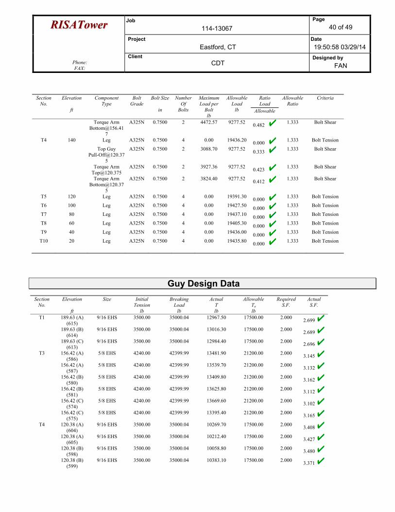
RRIISSAATToowweerr Job 114-13067
Page 40 of 49
Project Eastford, CT
Date 19:50:58 03/29/14
Phone: FAX:
Client CDT
Designed by FAN
Section No.
Elevation
ft
Component Type
Bolt Grade
Bolt Size
in
NumberOf
Bolts
MaximumLoad per
Bolt lb
AllowableLoad
lb
Ratio Load
Allowable
Allowable Ratio
Criteria
Torque Arm [email protected]
7
A325N 0.7500 2 4472.57 9277.52 0.482 1.333 Bolt Shear
T4 140 Leg A325N 0.7500 4 0.00 19436.20 0.000 1.333 Bolt Tension
Top Guy [email protected]
5
A325N 0.7500 2 3088.70 9277.52 0.333 1.333 Bolt Shear
Torque Arm [email protected]
A325N 0.7500 2 3927.36 9277.52 0.423 1.333 Bolt Shear
Torque Arm [email protected]
5
A325N 0.7500 2 3824.40 9277.52 0.412 1.333 Bolt Shear
T5 120 Leg A325N 0.7500 4 0.00 19391.30 0.000 1.333 Bolt Tension
T6 100 Leg A325N 0.7500 4 0.00 19427.50 0.000 1.333 Bolt Tension
T7 80 Leg A325N 0.7500 4 0.00 19437.10 0.000 1.333 Bolt Tension
T8 60 Leg A325N 0.7500 4 0.00 19405.30 0.000 1.333 Bolt Tension
T9 40 Leg A325N 0.7500 4 0.00 19436.00 0.000 1.333 Bolt Tension
T10 20 Leg A325N 0.7500 4 0.00 19435.80 0.000 1.333 Bolt Tension
Guy Design Data Section
No. Elevation
ft
Size
Initial Tension
lb
Breaking Load
lb
Actual T lb
Allowable Ta lb
Required S.F.
Actual S.F.
T1 189.63 (A)
(615) 9/16 EHS 3500.00 35000.04 12967.50 17500.00 2.000 2.699
189.63 (B) (614)
9/16 EHS 3500.00 35000.04 13016.30 17500.00 2.000 2.689
189.63 (C) (613)
9/16 EHS 3500.00 35000.04 12984.40 17500.00 2.000 2.696
T3 156.42 (A) (586)
5/8 EHS 4240.00 42399.99 13481.90 21200.00 2.000 3.145
156.42 (A) (587)
5/8 EHS 4240.00 42399.99 13539.70 21200.00 2.000 3.132
156.42 (B) (580)
5/8 EHS 4240.00 42399.99 13409.80 21200.00 2.000 3.162
156.42 (B) (581)
5/8 EHS 4240.00 42399.99 13625.80 21200.00 2.000 3.112
156.42 (C) (574)
5/8 EHS 4240.00 42399.99 13669.60 21200.00 2.000 3.102
156.42 (C) (575)
5/8 EHS 4240.00 42399.99 13395.40 21200.00 2.000 3.165
T4 120.38 (A) (604)
9/16 EHS 3500.00 35000.04 10269.70 17500.00 2.000 3.408
120.38 (A) (605)
9/16 EHS 3500.00 35000.04 10212.40 17500.00 2.000 3.427
120.38 (B) (598)
9/16 EHS 3500.00 35000.04 10058.80 17500.00 2.000 3.480
120.38 (B) (599)
9/16 EHS 3500.00 35000.04 10383.10 17500.00 2.000 3.371
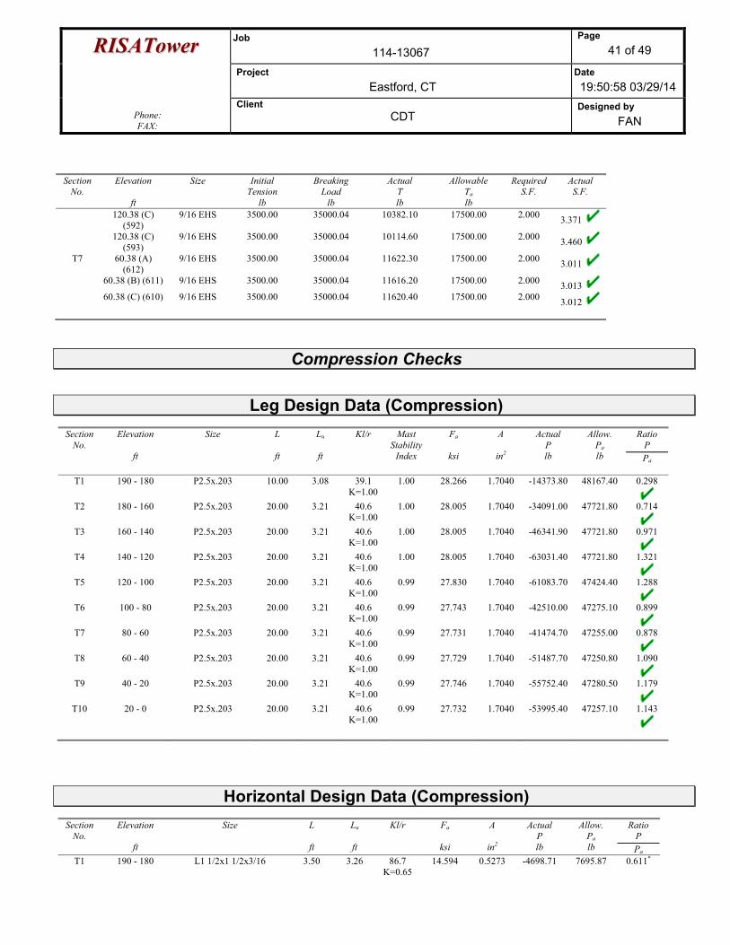
RRIISSAATToowweerr Job 114-13067
Page 41 of 49
Project Eastford, CT
Date 19:50:58 03/29/14
Phone: FAX:
Client CDT
Designed by FAN
Section No.
Elevation
ft
Size
Initial Tension
lb
Breaking Load
lb
Actual T lb
Allowable Ta lb
Required S.F.
Actual S.F.
120.38 (C)
(592) 9/16 EHS 3500.00 35000.04 10382.10 17500.00 2.000 3.371
120.38 (C) (593)
9/16 EHS 3500.00 35000.04 10114.60 17500.00 2.000 3.460
T7 60.38 (A) (612)
9/16 EHS 3500.00 35000.04 11622.30 17500.00 2.000 3.011
60.38 (B) (611) 9/16 EHS 3500.00 35000.04 11616.20 17500.00 2.000 3.013 60.38 (C) (610) 9/16 EHS 3500.00 35000.04 11620.40 17500.00 2.000 3.012
Compression Checks
Leg Design Data (Compression)
Section No.
Elevation
ft
Size
L
ft
Lu
ft
Kl/r
Mast Stability
Index
Fa
ksi
A
in2
Actual P lb
Allow. Pa lb
Ratio P Pa
T1 190 - 180 P2.5x.203 10.00 3.08 39.1 K=1.00
1.00 28.266 1.7040 -14373.80 48167.40 0.298
T2 180 - 160 P2.5x.203 20.00 3.21 40.6 K=1.00
1.00 28.005 1.7040 -34091.00 47721.80 0.714
T3 160 - 140 P2.5x.203 20.00 3.21 40.6 K=1.00
1.00 28.005 1.7040 -46341.90 47721.80 0.971
T4 140 - 120 P2.5x.203 20.00 3.21 40.6 K=1.00
1.00 28.005 1.7040 -63031.40 47721.80 1.321
T5 120 - 100 P2.5x.203 20.00 3.21 40.6 K=1.00
0.99 27.830 1.7040 -61083.70 47424.40 1.288
T6 100 - 80 P2.5x.203 20.00 3.21 40.6 K=1.00
0.99 27.743 1.7040 -42510.00 47275.10 0.899
T7 80 - 60 P2.5x.203 20.00 3.21 40.6 K=1.00
0.99 27.731 1.7040 -41474.70 47255.00 0.878
T8 60 - 40 P2.5x.203 20.00 3.21 40.6 K=1.00
0.99 27.729 1.7040 -51487.70 47250.80 1.090
T9 40 - 20 P2.5x.203 20.00 3.21 40.6 K=1.00
0.99 27.746 1.7040 -55752.40 47280.50 1.179
T10 20 - 0 P2.5x.203 20.00 3.21 40.6 K=1.00
0.99 27.732 1.7040 -53995.40 47257.10 1.143
Horizontal Design Data (Compression)
Section No.
Elevation
ft
Size
L
ft
Lu
ft
Kl/r
Fa
ksi
A
in2
Actual P lb
Allow. Pa lb
Ratio P Pa
T1 190 - 180 L1 1/2x1 1/2x3/16 3.50 3.26 86.7 K=0.65
14.594 0.5273 -4698.71 7695.87 0.611*
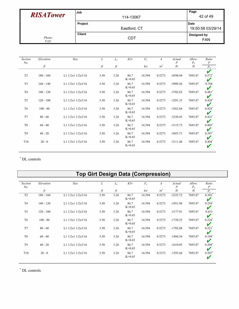
RRIISSAATToowweerr Job 114-13067
Page 42 of 49
Project Eastford, CT
Date 19:50:58 03/29/14
Phone: FAX:
Client CDT
Designed by FAN
Section No.
Elevation
ft
Size
L
ft
Lu
ft
Kl/r
Fa
ksi
A
in2
Actual P lb
Allow. Pa lb
Ratio P Pa
T2 180 - 160 L1 1/2x1 1/2x3/16 3.50 3.26 86.7 K=0.65
14.594 0.5273 -4398.94 7695.87 0.572*
T3 160 - 140 L1 1/2x1 1/2x3/16 3.50 3.26 86.7 K=0.65
14.594 0.5273 -5909.26 7695.87 0.768
T4 140 - 120 L1 1/2x1 1/2x3/16 3.50 3.26 86.7 K=0.65
14.594 0.5273 -3702.65 7695.87 0.481*
T5 120 - 100 L1 1/2x1 1/2x3/16 3.50 3.26 86.7 K=0.65
14.594 0.5273 -3291.33 7695.87 0.428*
T6 100 - 80 L1 1/2x1 1/2x3/16 3.50 3.26 86.7 K=0.65
14.594 0.5273 -3262.84 7695.87 0.424*
T7 80 - 60 L1 1/2x1 1/2x3/16 3.50 3.26 86.7 K=0.65
14.594 0.5273 -3320.45 7695.87 0.431*
T8 60 - 40 L1 1/2x1 1/2x3/16 3.50 3.26 86.7 K=0.65
14.594 0.5273 -3115.73 7695.87 0.405*
T9 40 - 20 L1 1/2x1 1/2x3/16 3.50 3.26 86.7 K=0.65
14.594 0.5273 -3053.71 7695.87 0.397*
T10 20 - 0 L1 1/2x1 1/2x3/16 3.50 3.26 86.7 K=0.65
14.594 0.5273 -3111.46 7695.87 0.404*
* DL controls
Top Girt Design Data (Compression)
Section No.
Elevation
ft
Size
L
ft
Lu
ft
Kl/r
Fa
ksi
A
in2
Actual P lb
Allow. Pa lb
Ratio P Pa
T2 180 - 160 L1 1/2x1 1/2x3/16 3.50 3.26 86.7 K=0.65
14.594 0.5273 -2325.72 7695.87 0.302*
T4 140 - 120 L1 1/2x1 1/2x3/16 3.50 3.26 86.7 K=0.65
14.594 0.5273 -1951.98 7695.87 0.254*
T5 120 - 100 L1 1/2x1 1/2x3/16 3.50 3.26 86.7 K=0.65
14.594 0.5273 -3177.91 7695.87 0.413
T6 100 - 80 L1 1/2x1 1/2x3/16 3.50 3.26 86.7 K=0.65
14.594 0.5273 -1720.25 7695.87 0.224*
T7 80 - 60 L1 1/2x1 1/2x3/16 3.50 3.26 86.7 K=0.65
14.594 0.5273 -1702.88 7695.87 0.221*
T8 60 - 40 L1 1/2x1 1/2x3/16 3.50 3.26 86.7 K=0.65
14.594 0.5273 -1494.36 7695.87 0.194*
T9 40 - 20 L1 1/2x1 1/2x3/16 3.50 3.26 86.7 K=0.65
14.594 0.5273 -1610.05 7695.87 0.209*
T10 20 - 0 L1 1/2x1 1/2x3/16 3.50 3.26 86.7 K=0.65
14.594 0.5273 -1592.66 7695.87 0.207*
* DL controls
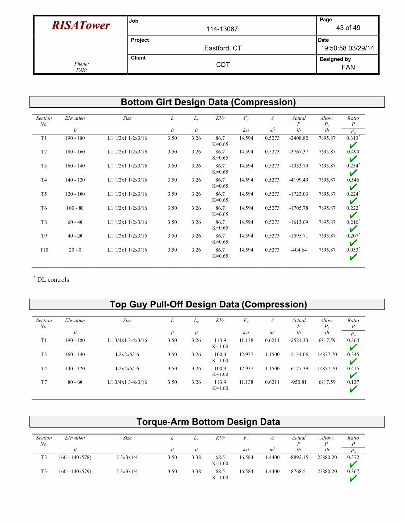
RRIISSAATToowweerr Job 114-13067
Page 43 of 49
Project Eastford, CT
Date 19:50:58 03/29/14
Phone: FAX:
Client CDT
Designed by FAN
Bottom Girt Design Data (Compression)
Section No.
Elevation
ft
Size
L
ft
Lu
ft
Kl/r
Fa
ksi
A
in2
Actual P lb
Allow. Pa lb
Ratio P Pa
T1 190 - 180 L1 1/2x1 1/2x3/16 3.50 3.26 86.7 K=0.65
14.594 0.5273 -2408.82 7695.87 0.313*
T2 180 - 160 L1 1/2x1 1/2x3/16 3.50 3.26 86.7 K=0.65
14.594 0.5273 -3767.37 7695.87 0.490
T3 160 - 140 L1 1/2x1 1/2x3/16 3.50 3.26 86.7 K=0.65
14.594 0.5273 -1953.79 7695.87 0.254*
T4 140 - 120 L1 1/2x1 1/2x3/16 3.50 3.26 86.7 K=0.65
14.594 0.5273 -4199.49 7695.87 0.546
T5 120 - 100 L1 1/2x1 1/2x3/16 3.50 3.26 86.7 K=0.65
14.594 0.5273 -1723.03 7695.87 0.224*
T6 100 - 80 L1 1/2x1 1/2x3/16 3.50 3.26 86.7 K=0.65
14.594 0.5273 -1705.78 7695.87 0.222*
T8 60 - 40 L1 1/2x1 1/2x3/16 3.50 3.26 86.7 K=0.65
14.594 0.5273 -1613.09 7695.87 0.210*
T9 40 - 20 L1 1/2x1 1/2x3/16 3.50 3.26 86.7 K=0.65
14.594 0.5273 -1595.71 7695.87 0.207*
T10 20 - 0 L1 1/2x1 1/2x3/16 3.50 3.26 86.7 K=0.65
14.594 0.5273 -404.64 7695.87 0.053*
* DL controls
Top Guy Pull-Off Design Data (Compression)
Section No.
Elevation
ft
Size
L
ft
Lu
ft
Kl/r
Fa
ksi
A
in2
Actual P lb
Allow. Pa lb
Ratio P Pa
T1 190 - 180 L1 3/4x1 3/4x3/16 3.50 3.26 113.9 K=1.00
11.138 0.6211 -2521.33 6917.59 0.364
T3 160 - 140 L2x2x5/16 3.50 3.26 100.3 K=1.00
12.937 1.1500 -5134.06 14877.70 0.345
T4 140 - 120 L2x2x5/16 3.50 3.26 100.3 K=1.00
12.937 1.1500 -6177.39 14877.70 0.415
T7 80 - 60 L1 3/4x1 3/4x3/16 3.50 3.26 113.9 K=1.00
11.138 0.6211 -950.81 6917.59 0.137
Torque-Arm Bottom Design Data
Section No.
Elevation
ft
Size
L
ft
Lu
ft
Kl/r
Fa
ksi
A
in2
Actual P lb
Allow. Pa lb
Ratio P Pa
T3 160 - 140 (578) L3x3x1/4 3.50 3.38 68.5 K=1.00
16.584 1.4400 -8892.15 23880.20 0.372
T3 160 - 140 (579) L3x3x1/4 3.50 3.38 68.5 K=1.00
16.584 1.4400 -8768.51 23880.20 0.367

RRIISSAATToowweerr Job 114-13067
Page 44 of 49
Project Eastford, CT
Date 19:50:58 03/29/14
Phone: FAX:
Client CDT
Designed by FAN
Section No.
Elevation
ft
Size
L
ft
Lu
ft
Kl/r
Fa
ksi
A
in2
Actual P lb
Allow. Pa lb
Ratio P Pa
T3 160 - 140 (584) L3x3x1/4 3.50 3.38 68.5 K=1.00
16.584 1.4400 -8740.21 23880.20 0.366
T3 160 - 140 (585) L3x3x1/4 3.50 3.38 68.5 K=1.00
16.584 1.4400 -8786.15 23880.20 0.368
T3 160 - 140 (590) L3x3x1/4 3.50 3.38 68.5 K=1.00
16.584 1.4400 -8945.14 23880.20 0.375
T3 160 - 140 (591) L3x3x1/4 3.50 3.38 68.5 K=1.00
16.584 1.4400 -8867.61 23880.20 0.371
T4 140 - 120 (596) L3x3x1/4 3.50 3.38 68.5 K=1.00
16.584 1.4400 -7520.14 23880.20 0.315
T4 140 - 120 (597) L3x3x1/4 3.50 3.38 68.5 K=1.00
16.584 1.4400 -7491.40 23880.20 0.314
T4 140 - 120 (602) L3x3x1/4 3.50 3.38 68.5 K=1.00
16.584 1.4400 -7299.36 23880.20 0.306
T4 140 - 120 (603) L3x3x1/4 3.50 3.38 68.5 K=1.00
16.584 1.4400 -7270.79 23880.20 0.304
T4 140 - 120 (608) L3x3x1/4 3.50 3.38 68.5 K=1.00
16.584 1.4400 -7648.80 23880.20 0.320
T4 140 - 120 (609) L3x3x1/4 3.50 3.38 68.5 K=1.00
16.584 1.4400 -7648.76 23880.20 0.320
Tension Checks
Leg Design Data (Tension)
Section No.
Elevation
ft
Size
L
ft
Lu
ft
Kl/r
Fa
ksi
A
in2
Actual P lb
Allow. Pa lb
Ratio P Pa
T1 190 - 180 P2.5x.203 10.00 3.08 39.1 33.000 1.7040 2915.35 56233.70 0.052
T2 180 - 160 P2.5x.203 20.00 3.21 40.6 33.000 1.7040 11750.90 56233.70 0.209
T3 160 - 140 P2.5x.203 20.00 3.21 40.6 33.000 1.7040 11749.90 56233.70 0.209
Diagonal Design Data (Tension)
Section No.
Elevation
ft
Size
L
ft
Lu
ft
Kl/r
Fa
ksi
A
in2
Actual P lb
Allow. Pa lb
Ratio P Pa
T1 190 - 180 5/8 4.66 4.35 333.7 21.600 0.3068 3397.02 6626.80 0.513*
T2 180 - 160 5/8 4.75 4.42 339.7 21.600 0.3068 7194.65 6626.80 1.086
T3 160 - 140 5/8 4.75 4.42 339.7 21.600 0.3068 4123.03 6626.80 0.622
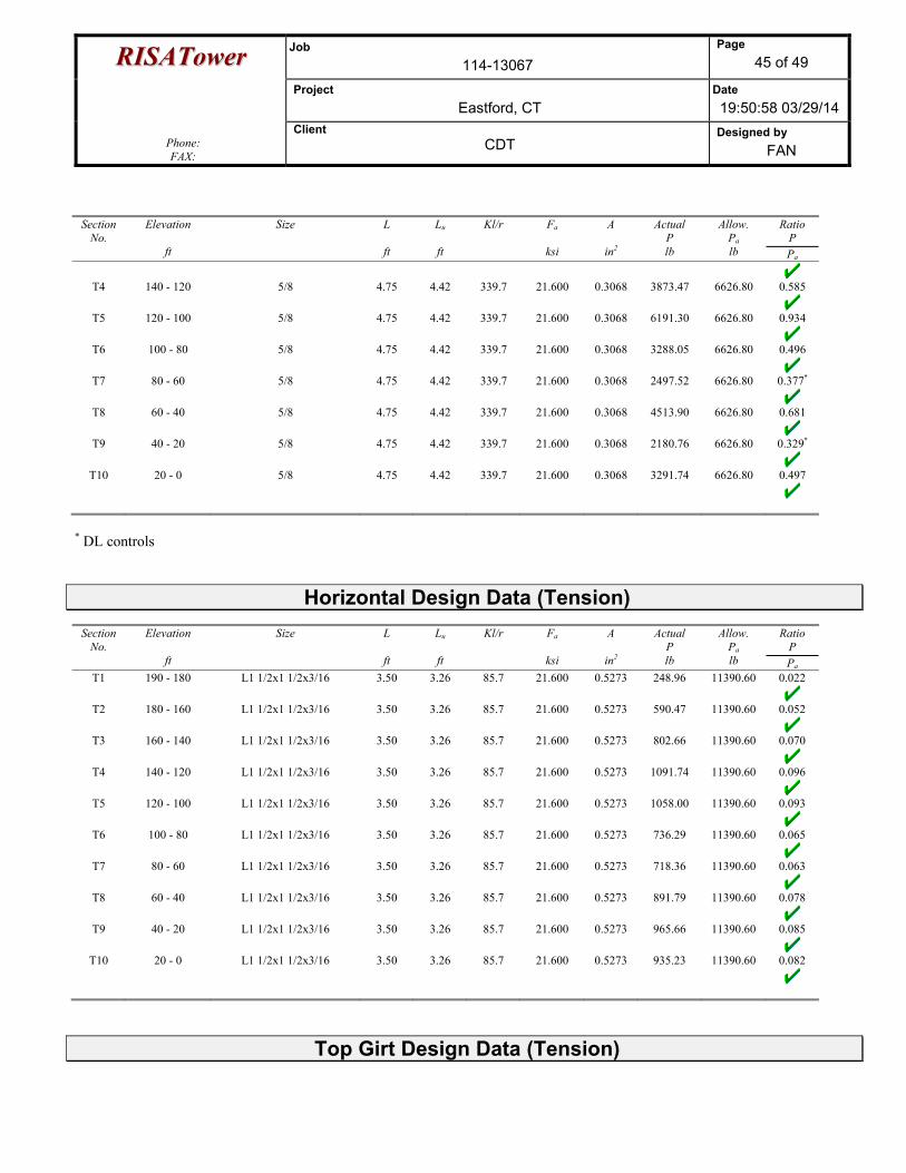
RRIISSAATToowweerr Job 114-13067
Page 45 of 49
Project Eastford, CT
Date 19:50:58 03/29/14
Phone: FAX:
Client CDT
Designed by FAN
Section No.
Elevation
ft
Size
L
ft
Lu
ft
Kl/r
Fa
ksi
A
in2
Actual P lb
Allow. Pa lb
Ratio P Pa
T4 140 - 120 5/8 4.75 4.42 339.7 21.600 0.3068 3873.47 6626.80 0.585
T5 120 - 100 5/8 4.75 4.42 339.7 21.600 0.3068 6191.30 6626.80 0.934
T6 100 - 80 5/8 4.75 4.42 339.7 21.600 0.3068 3288.05 6626.80 0.496
T7 80 - 60 5/8 4.75 4.42 339.7 21.600 0.3068 2497.52 6626.80 0.377*
T8 60 - 40 5/8 4.75 4.42 339.7 21.600 0.3068 4513.90 6626.80 0.681
T9 40 - 20 5/8 4.75 4.42 339.7 21.600 0.3068 2180.76 6626.80 0.329*
T10 20 - 0 5/8 4.75 4.42 339.7 21.600 0.3068 3291.74 6626.80 0.497
* DL controls
Horizontal Design Data (Tension)
Section No.
Elevation
ft
Size
L
ft
Lu
ft
Kl/r
Fa
ksi
A
in2
Actual P lb
Allow. Pa lb
Ratio P Pa
T1 190 - 180 L1 1/2x1 1/2x3/16 3.50 3.26 85.7 21.600 0.5273 248.96 11390.60 0.022
T2 180 - 160 L1 1/2x1 1/2x3/16 3.50 3.26 85.7 21.600 0.5273 590.47 11390.60 0.052
T3 160 - 140 L1 1/2x1 1/2x3/16 3.50 3.26 85.7 21.600 0.5273 802.66 11390.60 0.070
T4 140 - 120 L1 1/2x1 1/2x3/16 3.50 3.26 85.7 21.600 0.5273 1091.74 11390.60 0.096
T5 120 - 100 L1 1/2x1 1/2x3/16 3.50 3.26 85.7 21.600 0.5273 1058.00 11390.60 0.093
T6 100 - 80 L1 1/2x1 1/2x3/16 3.50 3.26 85.7 21.600 0.5273 736.29 11390.60 0.065
T7 80 - 60 L1 1/2x1 1/2x3/16 3.50 3.26 85.7 21.600 0.5273 718.36 11390.60 0.063
T8 60 - 40 L1 1/2x1 1/2x3/16 3.50 3.26 85.7 21.600 0.5273 891.79 11390.60 0.078
T9 40 - 20 L1 1/2x1 1/2x3/16 3.50 3.26 85.7 21.600 0.5273 965.66 11390.60 0.085
T10 20 - 0 L1 1/2x1 1/2x3/16 3.50 3.26 85.7 21.600 0.5273 935.23 11390.60 0.082
Top Girt Design Data (Tension)
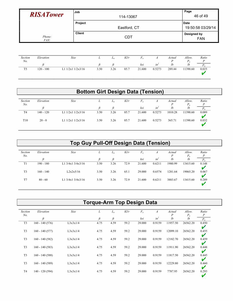
RRIISSAATToowweerr Job 114-13067
Page 46 of 49
Project Eastford, CT
Date 19:50:58 03/29/14
Phone: FAX:
Client CDT
Designed by FAN
Section No.
Elevation
ft
Size
L
ft
Lu
ft
Kl/r
Fa
ksi
A
in2
Actual P lb
Allow. Pa lb
Ratio P Pa
T5 120 - 100 L1 1/2x1 1/2x3/16 3.50 3.26 85.7 21.600 0.5273 289.44 11390.60 0.025
Bottom Girt Design Data (Tension)
Section No.
Elevation
ft
Size
L
ft
Lu
ft
Kl/r
Fa
ksi
A
in2
Actual P lb
Allow. Pa lb
Ratio P Pa
T4 140 - 120 L1 1/2x1 1/2x3/16 3.50 3.26 85.7 21.600 0.5273 1010.28 11390.60 0.089
T10 20 - 0 L1 1/2x1 1/2x3/16 3.50 3.26 85.7 21.600 0.5273 365.71 11390.60 0.032
Top Guy Pull-Off Design Data (Tension)
Section No.
Elevation
ft
Size
L
ft
Lu
ft
Kl/r
Fa
ksi
A
in2
Actual P lb
Allow. Pa lb
Ratio P Pa
T1 190 - 180 L1 3/4x1 3/4x3/16 3.50 3.26 72.9 21.600 0.6211 1980.99 13415.60 0.148
T3 160 - 140 L2x2x5/16 3.50 3.26 65.1 29.000 0.6574 1281.64 19065.20 0.067
T7 80 - 60 L1 3/4x1 3/4x3/16 3.50 3.26 72.9 21.600 0.6211 3883.67 13415.60 0.289
Torque-Arm Top Design Data
Section No.
Elevation
ft
Size
L
ft
Lu
ft
Kl/r
Fa
ksi
A
in2
Actual P lb
Allow. Pa lb
Ratio P Pa
T3 160 - 140 (576) L3x3x1/4 4.75 4.59 59.2 29.000 0.9159 11957.50 26562.20 0.450
T3 160 - 140 (577) L3x3x1/4 4.75 4.59 59.2 29.000 0.9159 12099.10 26562.20 0.455
T3 160 - 140 (582) L3x3x1/4 4.75 4.59 59.2 29.000 0.9159 12182.70 26562.20 0.459
T3 160 - 140 (583) L3x3x1/4 4.75 4.59 59.2 29.000 0.9159 11911.90 26562.20 0.448
T3 160 - 140 (588) L3x3x1/4 4.75 4.59 59.2 29.000 0.9159 11817.50 26562.20 0.445
T3 160 - 140 (589) L3x3x1/4 4.75 4.59 59.2 29.000 0.9159 12229.80 26562.20 0.460
T4 140 - 120 (594) L3x3x1/4 4.75 4.59 59.2 29.000 0.9159 7787.95 26562.20 0.293
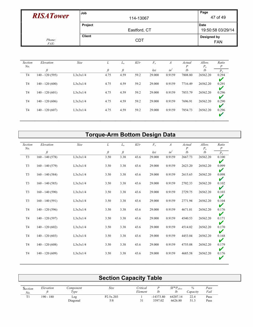
RRIISSAATToowweerr Job 114-13067
Page 47 of 49
Project Eastford, CT
Date 19:50:58 03/29/14
Phone: FAX:
Client CDT
Designed by FAN
Section No.
Elevation
ft
Size
L
ft
Lu
ft
Kl/r
Fa
ksi
A
in2
Actual P lb
Allow. Pa lb
Ratio P Pa
T4 140 - 120 (595) L3x3x1/4 4.75 4.59 59.2 29.000 0.9159 7808.80 26562.20 0.294
T4 140 - 120 (600) L3x3x1/4 4.75 4.59 59.2 29.000 0.9159 7716.49 26562.20 0.291
T4 140 - 120 (601) L3x3x1/4 4.75 4.59 59.2 29.000 0.9159 7853.79 26562.20 0.296
T4 140 - 120 (606) L3x3x1/4 4.75 4.59 59.2 29.000 0.9159 7696.91 26562.20 0.290
T4 140 - 120 (607) L3x3x1/4 4.75 4.59 59.2 29.000 0.9159 7854.73 26562.20 0.296
Torque-Arm Bottom Design Data
Section No.
Elevation
ft
Size
L
ft
Lu
ft
Kl/r
Fa
ksi
A
in2
Actual P lb
Allow. Pa lb
Ratio P Pa
T3 160 - 140 (578) L3x3x1/4 3.50 3.38 43.6 29.000 0.9159 2667.73 26562.20 0.100
T3 160 - 140 (579) L3x3x1/4 3.50 3.38 43.6 29.000 0.9159 2623.20 26562.20 0.099
T3 160 - 140 (584) L3x3x1/4 3.50 3.38 43.6 29.000 0.9159 2615.65 26562.20 0.098
T3 160 - 140 (585) L3x3x1/4 3.50 3.38 43.6 29.000 0.9159 2702.33 26562.20 0.102
T3 160 - 140 (590) L3x3x1/4 3.50 3.38 43.6 29.000 0.9159 2729.75 26562.20 0.103
T3 160 - 140 (591) L3x3x1/4 3.50 3.38 43.6 29.000 0.9159 2771.94 26562.20 0.104
T4 140 - 120 (596) L3x3x1/4 3.50 3.38 43.6 29.000 0.9159 4671.01 26562.20 0.176
T4 140 - 120 (597) L3x3x1/4 3.50 3.38 43.6 29.000 0.9159 4540.53 26562.20 0.171
T4 140 - 120 (602) L3x3x1/4 3.50 3.38 43.6 29.000 0.9159 4514.02 26562.20 0.170
T4 140 - 120 (603) L3x3x1/4 3.50 3.38 43.6 29.000 0.9159 4453.04 26562.20 0.168
T4 140 - 120 (608) L3x3x1/4 3.50 3.38 43.6 29.000 0.9159 4755.08 26562.20 0.179
T4 140 - 120 (609) L3x3x1/4 3.50 3.38 43.6 29.000 0.9159 4685.58 26562.20 0.176
Section Capacity Table Section
No. Elevation
ft Component
Type Size Critical
Element P lb
SF*Pallow lb
% Capacity
Pass Fail
T1 190 - 180 Leg P2.5x.203 1 -14373.80 64207.14 22.4 Pass Diagonal 5/8 31 3397.02 6626.80 51.3 Pass
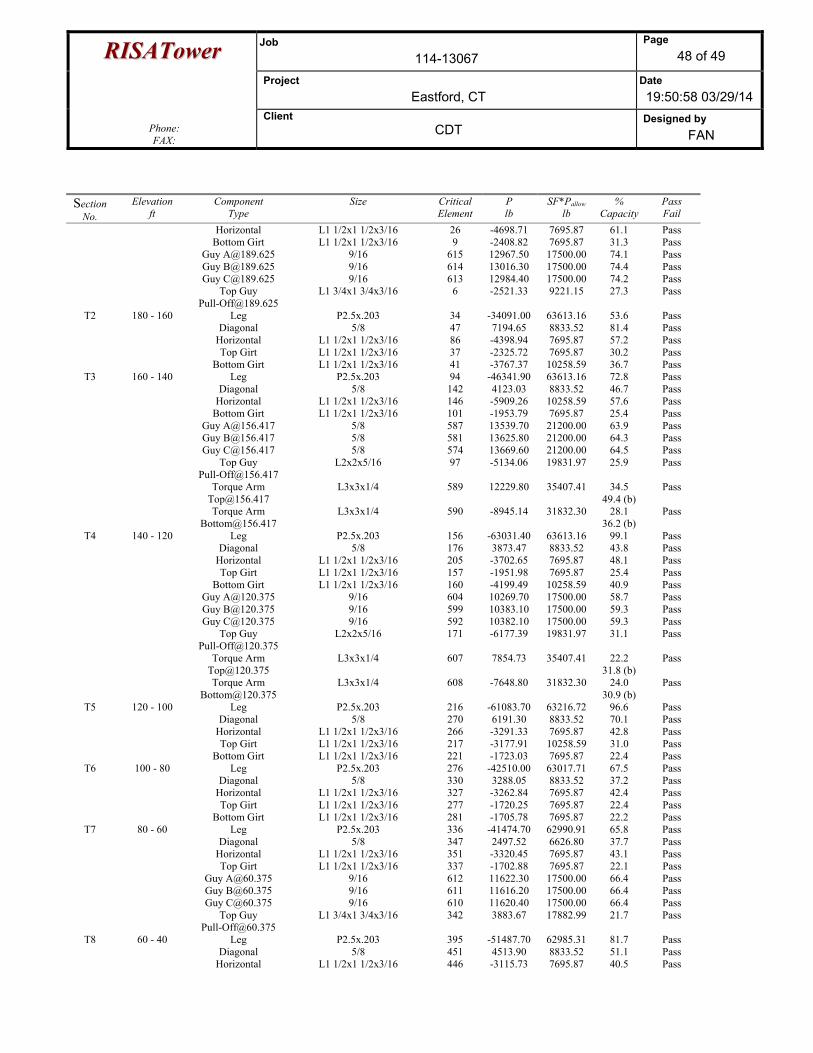
RRIISSAATToowweerr Job 114-13067
Page 48 of 49
Project Eastford, CT
Date 19:50:58 03/29/14
Phone: FAX:
Client CDT
Designed by FAN
Section No.
Elevation ft
Component Type
Size CriticalElement
P lb
SF*Pallow lb
% Capacity
Pass Fail
Horizontal L1 1/2x1 1/2x3/16 26 -4698.71 7695.87 61.1 Pass Bottom Girt L1 1/2x1 1/2x3/16 9 -2408.82 7695.87 31.3 Pass Guy [email protected] 9/16 615 12967.50 17500.00 74.1 Pass Guy [email protected] 9/16 614 13016.30 17500.00 74.4 Pass Guy [email protected] 9/16 613 12984.40 17500.00 74.2 Pass Top Guy
[email protected] L1 3/4x1 3/4x3/16 6 -2521.33 9221.15 27.3 Pass
T2 180 - 160 Leg P2.5x.203 34 -34091.00 63613.16 53.6 Pass Diagonal 5/8 47 7194.65 8833.52 81.4 Pass Horizontal L1 1/2x1 1/2x3/16 86 -4398.94 7695.87 57.2 Pass Top Girt L1 1/2x1 1/2x3/16 37 -2325.72 7695.87 30.2 Pass Bottom Girt L1 1/2x1 1/2x3/16 41 -3767.37 10258.59 36.7 Pass
T3 160 - 140 Leg P2.5x.203 94 -46341.90 63613.16 72.8 Pass Diagonal 5/8 142 4123.03 8833.52 46.7 Pass Horizontal L1 1/2x1 1/2x3/16 146 -5909.26 10258.59 57.6 Pass Bottom Girt L1 1/2x1 1/2x3/16 101 -1953.79 7695.87 25.4 Pass Guy [email protected] 5/8 587 13539.70 21200.00 63.9 Pass Guy [email protected] 5/8 581 13625.80 21200.00 64.3 Pass Guy [email protected] 5/8 574 13669.60 21200.00 64.5 Pass Top Guy
[email protected] L2x2x5/16 97 -5134.06 19831.97 25.9 Pass
Torque Arm [email protected]
L3x3x1/4 589 12229.80 35407.41 34.5 49.4 (b)
Pass
Torque Arm [email protected]
L3x3x1/4 590 -8945.14 31832.30 28.1 36.2 (b)
Pass
T4 140 - 120 Leg P2.5x.203 156 -63031.40 63613.16 99.1 Pass Diagonal 5/8 176 3873.47 8833.52 43.8 Pass Horizontal L1 1/2x1 1/2x3/16 205 -3702.65 7695.87 48.1 Pass Top Girt L1 1/2x1 1/2x3/16 157 -1951.98 7695.87 25.4 Pass Bottom Girt L1 1/2x1 1/2x3/16 160 -4199.49 10258.59 40.9 Pass Guy [email protected] 9/16 604 10269.70 17500.00 58.7 Pass Guy [email protected] 9/16 599 10383.10 17500.00 59.3 Pass Guy [email protected] 9/16 592 10382.10 17500.00 59.3 Pass Top Guy
[email protected] L2x2x5/16 171 -6177.39 19831.97 31.1 Pass
Torque Arm [email protected]
L3x3x1/4 607 7854.73 35407.41 22.2 31.8 (b)
Pass
Torque Arm [email protected]
L3x3x1/4 608 -7648.80 31832.30 24.0 30.9 (b)
Pass
T5 120 - 100 Leg P2.5x.203 216 -61083.70 63216.72 96.6 Pass Diagonal 5/8 270 6191.30 8833.52 70.1 Pass Horizontal L1 1/2x1 1/2x3/16 266 -3291.33 7695.87 42.8 Pass Top Girt L1 1/2x1 1/2x3/16 217 -3177.91 10258.59 31.0 Pass Bottom Girt L1 1/2x1 1/2x3/16 221 -1723.03 7695.87 22.4 Pass
T6 100 - 80 Leg P2.5x.203 276 -42510.00 63017.71 67.5 Pass Diagonal 5/8 330 3288.05 8833.52 37.2 Pass Horizontal L1 1/2x1 1/2x3/16 327 -3262.84 7695.87 42.4 Pass Top Girt L1 1/2x1 1/2x3/16 277 -1720.25 7695.87 22.4 Pass Bottom Girt L1 1/2x1 1/2x3/16 281 -1705.78 7695.87 22.2 Pass
T7 80 - 60 Leg P2.5x.203 336 -41474.70 62990.91 65.8 Pass Diagonal 5/8 347 2497.52 6626.80 37.7 Pass Horizontal L1 1/2x1 1/2x3/16 351 -3320.45 7695.87 43.1 Pass Top Girt L1 1/2x1 1/2x3/16 337 -1702.88 7695.87 22.1 Pass Guy [email protected] 9/16 612 11622.30 17500.00 66.4 Pass Guy [email protected] 9/16 611 11616.20 17500.00 66.4 Pass Guy [email protected] 9/16 610 11620.40 17500.00 66.4 Pass Top Guy
[email protected] L1 3/4x1 3/4x3/16 342 3883.67 17882.99 21.7 Pass
T8 60 - 40 Leg P2.5x.203 395 -51487.70 62985.31 81.7 Pass Diagonal 5/8 451 4513.90 8833.52 51.1 Pass Horizontal L1 1/2x1 1/2x3/16 446 -3115.73 7695.87 40.5 Pass
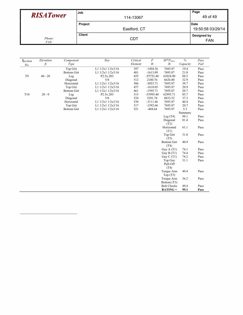
RRIISSAATToowweerr Job 114-13067
Page 49 of 49
Project Eastford, CT
Date 19:50:58 03/29/14
Phone: FAX:
Client CDT
Designed by FAN
Section No.
Elevation ft
Component Type
Size CriticalElement
P lb
SF*Pallow lb
% Capacity
Pass Fail
Top Girt L1 1/2x1 1/2x3/16 397 -1494.36 7695.87 19.4 Pass Bottom Girt L1 1/2x1 1/2x3/16 401 -1613.09 7695.87 21.0 Pass
T9 40 - 20 Leg P2.5x.203 455 -55752.40 63024.90 88.5 Pass Diagonal 5/8 512 2180.76 6626.80 32.9 Pass Horizontal L1 1/2x1 1/2x3/16 506 -3053.71 7695.87 39.7 Pass Top Girt L1 1/2x1 1/2x3/16 457 -1610.05 7695.87 20.9 Pass Bottom Girt L1 1/2x1 1/2x3/16 461 -1595.71 7695.87 20.7 Pass
T10 20 - 0 Leg P2.5x.203 515 -53995.40 62993.71 85.7 Pass Diagonal 5/8 524 3291.74 8833.52 37.3 Pass Horizontal L1 1/2x1 1/2x3/16 530 -3111.46 7695.87 40.4 Pass Top Girt L1 1/2x1 1/2x3/16 517 -1592.66 7695.87 20.7 Pass Bottom Girt L1 1/2x1 1/2x3/16 521 -404.64 7695.87 5.3 Pass Summary Leg (T4) 99.1 Pass Diagonal
(T2) 81.4 Pass
Horizontal (T1)
61.1 Pass
Top Girt (T5)
31.0 Pass
Bottom Girt (T4)
40.9 Pass
Guy A (T1) 74.1 Pass Guy B (T1) 74.4 Pass Guy C (T1) 74.2 Pass Top Guy
Pull-Off (T4)
31.1 Pass
Torque Arm Top (T3)
49.4 Pass
Torque Arm Bottom (T3)
36.2 Pass
Bolt Checks 49.4 Pass RATING = 99.1 Pass
�
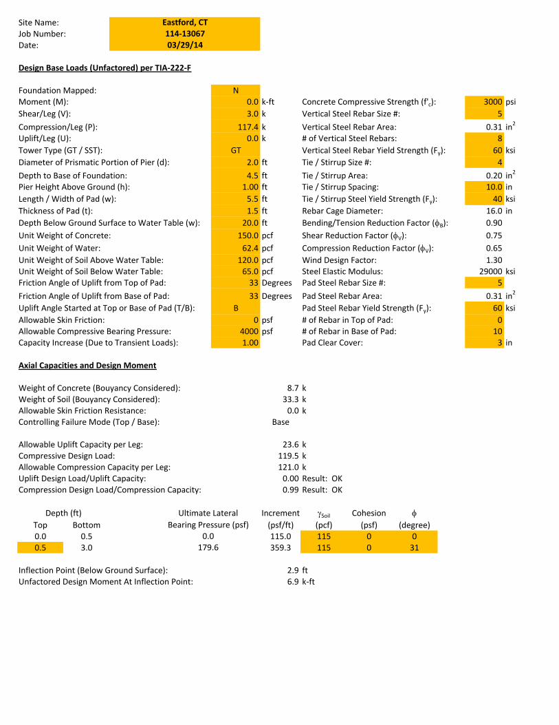
Site�Name:Job�Number:Date:
Design�Base�Loads�(Unfactored)�per�TIAͲ222ͲF
Foundation�Mapped: NMoment�(M): 0.0 kͲft Concrete�Compressive�Strength�(f'c): 3000 psiShear/Leg�(V): 3.0 k Vertical�Steel�Rebar�Size�#: 5Compression/Leg�(P): 117.4 k Vertical�Steel�Rebar�Area:� 0.31 in2
Uplift/Leg�(U): 0.0 k #�of�Vertical�Steel�Rebars: 8Tower�Type�(GT�/�SST): GT Vertical�Steel�Rebar�Yield�Strength�(Fy): 60 ksiDiameter�of�Prismatic�Portion�of�Pier�(d): 2.0 ft Tie�/�Stirrup�Size�#: 4Depth�to�Base�of�Foundation: 4.5 ft Tie�/�Stirrup�Area: 0.20 in2
Pier�Height�Above�Ground�(h): 1.00 ft Tie�/�Stirrup�Spacing: 10.0 inLength�/�Width�of�Pad�(w): 5.5 ft Tie�/�Stirrup�Steel�Yield�Strength�(Fy): 40 ksiThickness�of�Pad�(t): 1.5 ft Rebar�Cage�Diameter: 16.0 inDepth�Below�Ground�Surface�to�Water�Table�(w): 20.0 ft Bending/Tension�Reduction�Factor�(IB): 0.90Unit�Weight�of�Concrete: 150.0 pcf Shear�Reduction�Factor�(IV): 0.75Unit�Weight�of�Water: 62.4 pcf Compression�Reduction�Factor�(IV): 0.65Unit�Weight�of�Soil�Above�Water�Table: 120.0 pcf Wind�Design�Factor: 1.30Unit�Weight�of�Soil�Below�Water�Table: 65.0 pcf Steel�Elastic�Modulus: 29000 ksiFriction�Angle�of�Uplift�from�Top�of�Pad: 33 Degrees Pad�Steel�Rebar�Size�#: 5Friction�Angle�of�Uplift�from�Base�of�Pad: 33 Degrees Pad�Steel�Rebar�Area: 0.31 in2
Uplift�Angle�Started�at�Top�or�Base�of�Pad�(T/B): B Pad�Steel�Rebar�Yield�Strength�(Fy): 60 ksiAllowable�Skin�Friction: 0 psf #�of�Rebar�in�Top�of�Pad: 0Allowable�Compressive�Bearing�Pressure: 4000 psf #�of�Rebar�in�Base�of�Pad: 10Capacity�Increase�(Due�to�Transient�Loads): 1.00 Pad�Clear�Cover: 3 in
114Ͳ13067Eastford,�CT
03/29/14
Axial�Capacities�and�Design�Moment
Weight�of�Concrete�(Bouyancy�Considered): 8.7 kWeight�of�Soil�(Bouyancy�Considered): 33.3 kAllowable�Skin�Friction�Resistance: 0.0 kControlling�Failure�Mode�(Top�/�Base): Base
Allowable�Uplift�Capacity�per�Leg: 23.6 kCompressive�Design�Load: 119.5 kAllowable�Compression�Capacity�per�Leg: 121.0 kUplift�Design�Load/Uplift�Capacity: 0.00 Result:��OKCompression�Design�Load/Compression�Capacity: 0.99 Result:��OK
Increment JSoil Cohesion ITop Bottom (psf/ft) (pcf) (psf) (degree)0.0 0.5 115.0 115 0 00.5 3.0 359.3 115 0 31
Inflection�Point�(Below�Ground�Surface): 2.9 ftUnfactored�Design�Moment�At�Inflection�Point: 6.9 kͲft
Depth�(ft) Ultimate�LateralBearing�Pressure�(psf)
179.60.0
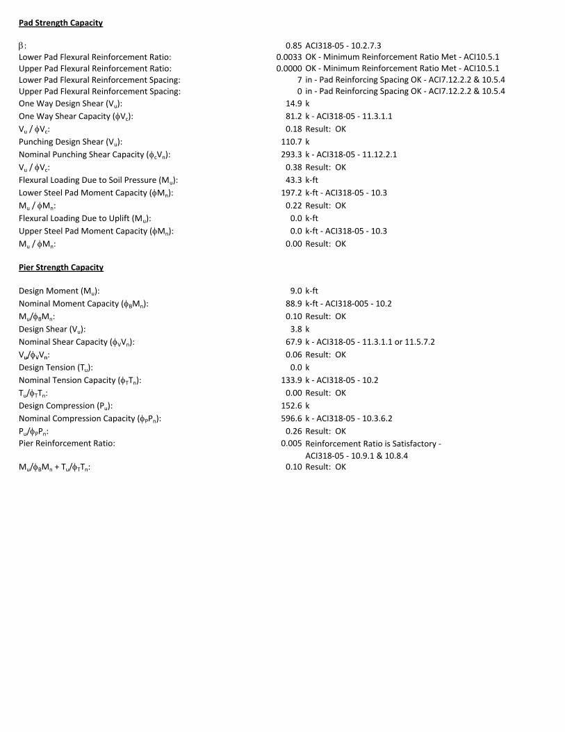
Pad�Strength�Capacity
E: 0.85 ACI318Ͳ05�Ͳ�10.2.7.3Lower�Pad�Flexural�Reinforcement�Ratio: 0.0033Upper�Pad�Flexural�Reinforcement�Ratio: 0.0000Lower�Pad�Flexural�Reinforcement�Spacing: 7Upper�Pad�Flexural�Reinforcement�Spacing: 0One�Way�Design�Shear�(Vu): 14.9 kOne�Way�Shear�Capacity�(IVc): 81.2 k�Ͳ�ACI318Ͳ05�Ͳ�11.3.1.1Vu�/�IVc: 0.18Punching�Design�Shear�(Vu): 110.7 kNominal�Punching�Shear�Capacity�(IcVn): 293.3 k�Ͳ�ACI318Ͳ05�Ͳ�11.12.2.1Vu�/�IVc: 0.38Flexural�Loading�Due�to�Soil�Pressure�(Mu): 43.3 kͲftLower�Steel�Pad�Moment�Capacity�(IMn): 197.2 kͲft�Ͳ�ACI318Ͳ05�Ͳ�10.3Mu�/�IMn: 0.22Flexural�Loading�Due�to�Uplift�(Mu): 0.0 kͲftUpper�Steel�Pad�Moment�Capacity�(IMn): 0.0 kͲft�Ͳ�ACI318Ͳ05�Ͳ�10.3Mu�/�IMn: 0.00
Pier�Strength�Capacity
Design�Moment�(Mu): 9.0 kͲftNominal�Moment�Capacity�(IBMn): 88.9 kͲft�Ͳ�ACI318Ͳ005�Ͳ�10.2Mu/IBMn: 0.10Design�Shear�(Vu): 3.8 kNominal�Shear�Capacity�(IVVn): 67.9 k�Ͳ�ACI318Ͳ05�Ͳ�11.3.1.1�or�11.5.7.2Vu/IVVn: 0.06
in�Ͳ�Pad�Reinforcing�Spacing�OK�Ͳ�ACI7.12.2.2�&�10.5.4
Result:��OK
Result:��OK
Result:��OK
OK�Ͳ�Minimum�Reinforcement�Ratio�Met�Ͳ�ACI10.5.1OK�Ͳ�Minimum�Reinforcement�Ratio�Met�Ͳ�ACI10.5.1
Result:��OK
Result:��OK
Result:��OK
in�Ͳ�Pad�Reinforcing�Spacing�OK�Ͳ�ACI7.12.2.2�&�10.5.4
u/IV n
Design�Tension�(Tu): 0.0 kNominal�Tension�Capacity�(ITTn): 133.9 k�Ͳ�ACI318Ͳ05�Ͳ�10.2Tu/ITTn: 0.00Design�Compression�(Pu): 152.6 kNominal�Compression�Capacity�(IPPn): 596.6 k�Ͳ�ACI318Ͳ05�Ͳ�10.3.6.2Pu/IPPn: 0.26Pier�Reinforcement�Ratio: 0.005
Mu/IBMn�+�Tu/ITTn: 0.10
Result:��OK
Result:��OK
Result:��OK
Reinforcement�Ratio�is�Satisfactory�Ͳ�ACI318Ͳ05�Ͳ�10.9.1�&�10.8.4
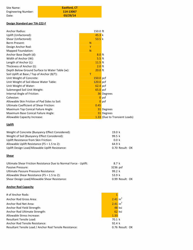
Site�Name:Engineering�Number:Date:
Design�Standard�per�TIAͲ222ͲF
Anchor�Radius: 150.0 ftUplift�(Unfactored): 45.3 kShear�(Unfactored): 53.5 kBerm�Present: NDesign�Anchor�Rod: YMapped�Foundation: NAnchor�Base�Depth�(d): 8.0 ftWidth�of�Anchor�(W): 5.5 ftLength�of�Anchor�(L): 11.5 ftThickness�of�Anchor�(t): 2.0 ftDepth�Below�Ground�Surface�to�Water�Table�(w): 20.0 ftSoil�Uplift�at�Base�/�Top�of�Anchor�(B/T): TUnit�Weight�of�Concrete: 150.0 pcfUnit�Weight�of�Soil�Above�Water�Table: 120.0 pcfUnit�Weight�of�Water: 62.4 pcfSubmerged�Soil�Unit�Weight: 65.0 pcfInternal�Angle�of�Friction: 36 Degrees Berm�Length: 10 ftCohesion: 0 psf Berm�Width 10 ftAllowable�Skin�Friction�of�Pad�Sides�to�Soil: 0 psf Berm�Thickness: 2.5 ftUltimate�Coefficient�of�Shear�Friction: 0.45 Soil�/�Concrete: SoilMaximum�Top�Conical�Failure�Angle: 31 DegreesMaximum�Base�Conical�Failure�Angle: 31 DegreesAllowable�Capacity�Increase: 1.33 (Due�to�Transient�Loads)
03/29/14
Eastford,�CT114Ͳ13067
Uplift
Weight�of�Concrete�(Buoyancy�Effect�Considered): 19.0 kWeight�of�Soil�(Buoyancy�Effect�Considered): 99.5 kUplift�Resistance�from�Skin�Friction: 0.0 kAllowable�Uplift�Resistance�(FS�=�1.5�to�2): 64.9 kUplift�Design�Load/Allowable�Uplift�Resistance: 0.70 Result:��OK
Shear
Ultimate�Shear�Friction�Resistance�Due�to�Normal�Force�Ͳ�Uplift: 8.7 kPassive�Pressure: 3236 psfUltimate�Passure�Pressure�Resistance: 99.2 kAllowable�Shear�Resistance�(FS�=�1.5�to�2): 53.9 kShear�Design�Load/Allowable�Shear�Resistance: 0.99 Result:��OK
Anchor�Rod�Capacity
#�of�Anchor�Rods: 1Anchor�Rod�Gross�Area: 2.41 in2
Anchor�Rod�Net�Area: 2.41 in2
Anchor�Rod�Yield�Strength: 48 ksiAnchor�Rod�Ultimate�Strength: 62 ksiAllowable�Stress�Increase: 1.33Resultant�Tensile�Load: 70.1 kAnchor�Rod�Tensile�Resistance: 92.4 kResultant�Tensile�Load�/�Anchor�Rod�Tensile�Resistance: 0.76 Result:��OK
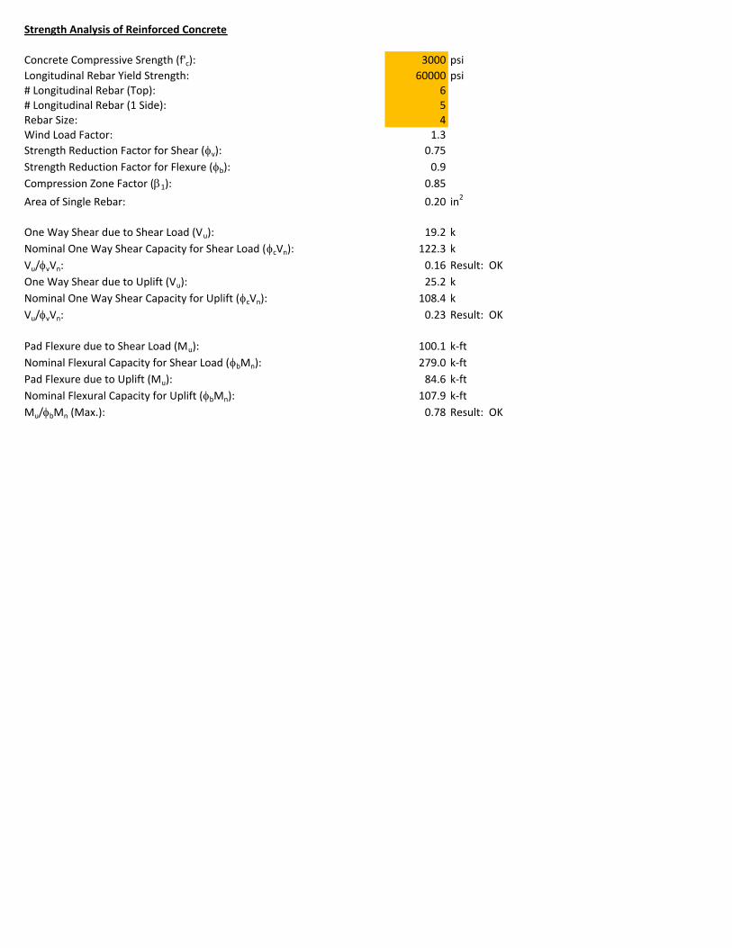
Strength�Analysis�of�Reinforced�Concrete
Concrete�Compressive�Srength�(f'c): 3000 psiLongitudinal�Rebar�Yield�Strength: 60000 psi#�Longitudinal�Rebar�(Top): 6#�Longitudinal�Rebar�(1�Side): 5Rebar�Size: 4Wind�Load�Factor: 1.3Strength�Reduction�Factor�for�Shear�(Iv): 0.75Strength�Reduction�Factor�for�Flexure�(Ib): 0.9Compression�Zone�Factor�(E1): 0.85Area�of�Single�Rebar: 0.20 in2
One�Way�Shear�due�to�Shear�Load�(Vu):�� 19.2 kNominal�One�Way�Shear�Capacity�for�Shear�Load�(IcVn): 122.3 kVu/IvVn: 0.16 Result:��OKOne�Way�Shear�due�to�Uplift�(Vu):�� 25.2 kNominal�One�Way�Shear�Capacity�for�Uplift�(IcVn): 108.4 kVu/IvVn: 0.23 Result:��OK
Pad�Flexure�due�to�Shear�Load�(Mu): 100.1 kͲftNominal�Flexural�Capacity�for�Shear�Load�(IbMn): 279.0 kͲftPad�Flexure�due�to�Uplift�(Mu): 84.6 kͲftNominal�Flexural�Capacity�for�Uplift�(IbMn): 107.9 kͲftMu/IbMn�(Max.): 0.78 Result:��OK

EBI Consulting environmental | engineering | due diligence
21 B Street . Burlington, MA 01803 . Tel: (781) 273.2500 . Fax: (781) 273.3311
RADIO FREQUENCY EMISSIONS ANALYSIS REPORT EVALUATION OF HUMAN EXPOSURE POTENTIAL
TO NON-IONIZING EMISSIONS
Sprint Existing Facility
Site ID: CT33XC016
Eastford 34 Old Toute 44
Eastford, CT 06242
October 25, 2012
EBI Consulting environmental | engineering | due diligence
21 B Street . Burlington, MA 01803 . Tel: (781) 273.2500 . Fax: (781) 273.3311
October 25, 2012
Sprint Attn: RF Engineering Manager 1 International Boulevard, Suite 800 Mahwah, NJ 07495
Re: Emissions Values for Site: CT33XC016 – Eastford
EBI Consulting was directed to analyze the proposed upgrades to the existing Sprint facility located at 34 Old Toute 44, Eastford, CT, for the purpose of determining whether the emissions from the proposed Sprint equipment upgrades on this property are within specified federal limits.
All information used in this report was analyzed as a percentage of current Maximum Permissible Exposure (% MPE) as listed in the FCC OET Bulletin 65 Edition 97-01and ANSI/IEEE Std C95.1. The
FCC regulates Maximum Permissible Exposure in units of microwatts per square centimeter (W/cm2).
The number of W/cm2 calculated at each sample point is called the power density. The exposure limit for power density varies depending upon the frequencies being utilized. Wireless Carriers and Paging Services use different frequency bands each with different exposure limits, therefore it is necessary to report results and limits in terms of percent MPE rather than power density.
All results were compared to the FCC (Federal Communications Commission) radio frequency exposure rules, 47 CFR 1.1307(b)(1) – (b)(3), to determine compliance with the Maximum Permissible Exposure (MPE) limits for General Population/Uncontrolled environments as defined below.
General population/uncontrolled exposure limits apply to situations in which the general public may be exposed or in which persons who are exposed as a consequence of their employment may not be made fully aware of the potential for exposure or cannot exercise control over their exposure. Therefore, members of the general public would always be considered under this category when exposure is not employment related, for example, in the case of a telecommunications tower that exposes persons in a nearby residential area.
Public exposure to radio frequencies is regulated and enforced in units of microwatts per square centimeter (μW/cm2). The general population exposure limit for the cellular band is approximately 567 μW/cm2, and the general population exposure limit for the PCS band is 1000 μW/cm2. Because each carrier will be using different frequency bands, and each frequency band has different exposure limits, it is necessary to report percent of MPE rather than power density.
EBI Consulting environmental | engineering | due diligence
21 B Street . Burlington, MA 01803 . Tel: (781) 273.2500 . Fax: (781) 273.3311
Occupational/controlled exposure limits apply to situations in which persons are exposed as a consequence of their employment and in which those persons who are exposed have been made fully aware of the potential for exposure and can exercise control over their exposure. Occupational/controlled exposure limits also apply where exposure is of a transient nature as a result of incidental passage through a location where exposure levels may be above general population/uncontrolled limits (see below), as long as the exposed person has been made fully aware of the potential for exposure and can exercise control over his or her exposure by leaving the area or by some other appropriate means.
Additional details can be found in FCC OET 65.
CALCULATIONS
Calculations were done for the proposed upgrades to the existing Sprint Wireless antenna facility located at 34 Old Toute 44, Eastford, CT, using the equipment information listed below. All calculations were performed per the specifications under FCC OET 65. All calculations were performed assuming the main lobe of the antenna was focused at the base of the tower to present a worst case scenario. Actual values seen from this site will be dramatically less than those shown in this report. For this report the sample point is the top of a 6 foot person standing at the base of the tower.
For all calculations, all emissions were calculated using the following assumptions:
1) 2 CDMA Carriers (1900 MHz) were considered for each sector of the proposed installation. 2) All radios at the proposed installation were considered to be running at full power and were
uncombined in their RF transmissions paths per carrier prescribed configuration. Per FCC OET Bulletin No. 65 - Edition 97-01 recommendations to achieve the maximum anticipated value at each sample point, all power levels emitting from the proposed antenna installation are increased by a factor of 2.56 to account for possible in-phase reflections from the surrounding environment. This is rarely the case, and if so, is never continuous.
3) For the following calculations the sample point was the top of a six foot person standing at the base of the tower. The actual gain in this direction was used per the manufactures supplied specifications.
4) The antenna used in this modeling is the DB980H90E-M. This is based on feedback from the carrier with regards to anticipated antenna selection. This antenna has a 14.95 dBd gain value at its main lobe at 1900 MHz. All calculations were performed assuming the main lobe of the antenna was focused at the base of the tower to present a worst case scenario.
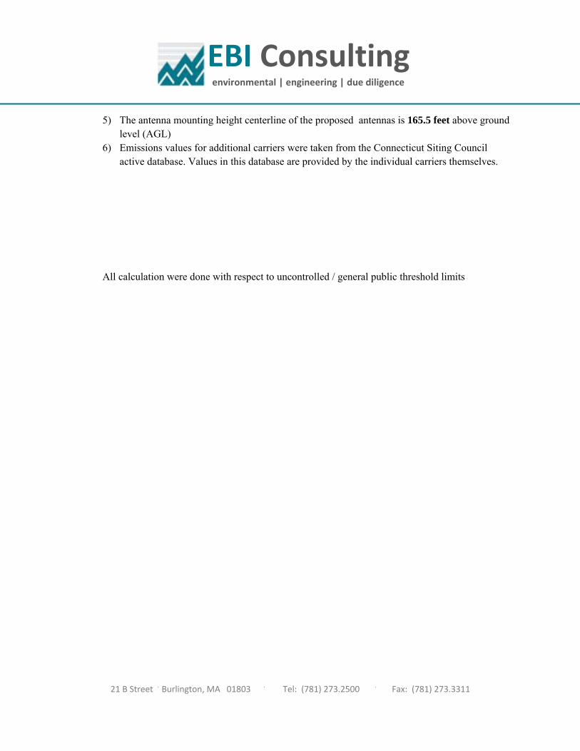
EBI Consulting environmental | engineering | due diligence
21 B Street . Burlington, MA 01803 . Tel: (781) 273.2500 . Fax: (781) 273.3311
5) The antenna mounting height centerline of the proposed antennas is 165.5 feet above ground level (AGL)
6) Emissions values for additional carriers were taken from the Connecticut Siting Council active database. Values in this database are provided by the individual carriers themselves.
All calculation were done with respect to uncontrolled / general public threshold limits
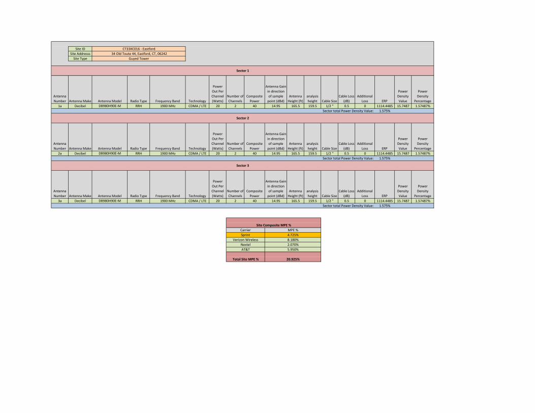
Site ID
Site AddresssSite Type
Antenna Number Antenna Make Antenna Model Radio Type Frequency Band Technology
Power Out Per Channel (Watts)
Number of Channels
Composite Power
Antenna Gain in direction of sample point (dBd)
Antenna Height (ft)
analysis height Cable Size
Cable Loss (dB)
Additional Loss ERP
Power Density Value
Power Density
Percentage
1a Decibel DB980H90E‐M RRH 1900 MHz CDMA / LTE 20 2 40 14.95 165.5 159.5 1/2 " 0.5 0 1114.4485 15.7487 1.57487%
1.575%
Antenna Number Antenna Make Antenna Model Radio Type Frequency Band Technology
Power Out Per Channel (Watts)
Number of Channels
Composite Power
Antenna Gain in direction of sample point (dBd)
Antenna Height (ft)
analysis height Cable Size
Cable Loss (dB)
Additional Loss ERP
Power Density Value
Power Density
Percentage
2a Decibel DB980H90E‐M RRH 1900 MHz CDMA / LTE 20 2 40 14.95 165.5 159.5 1/2 " 0.5 0 1114.4485 15.7487 1.57487%
1.575%
Antenna Number Antenna Make Antenna Model Radio Type Frequency Band Technology
Power Out Per Channel (Watts)
Number of Channels
Composite Power
Antenna Gain in direction of sample point (dBd)
Antenna Height (ft)
analysis height Cable Size
Cable Loss (dB)
Additional Loss ERP
Power Density Value
Power Density
Percentage
3a Decibel DB980H90E‐M RRH 1900 MHz CDMA / LTE 20 2 40 14.95 165.5 159.5 1/2 " 0.5 0 1114.4485 15.7487 1.57487%
1.575%
5.950%
MPE %4.725%
8.180%
Carrier
Sprint
Verizon Wireless
Nextel 2.070%
AT&T
Sector 1
Sector 2
Sector 3
34 Old Toute 44, Eastford, CT, 06242CT33XC016 ‐ Eastford
Guyed Tower
Sector total Power Density Value:
Sector total Power Density Value:
Sector total Power Density Value:
Site Composite MPE %
Total Site MPE % 20.925%
EBI Consulting environmental | engineering | due diligence
21 B Street . Burlington, MA 01803 . Tel: (781) 273.2500 . Fax: (781) 273.3311
Summary
All calculations performed for this analysis yielded results that were well within the allowable limits for general public exposure to RF Emissions.
The anticipated Maximum Composite contributions from the Sprint facility are 4.725% (1.575% from each sector) of the allowable FCC established general public limit considering all three sectors simultaneously sampled at the ground level.
The anticipated composite MPE value for this site assuming all carriers present is 20.925% of the allowable FCC established general public limit sampled at the ground level. This is based upon values listed in the Connecticut Siting Council database for existing carrier emissions
FCC guidelines state that if a site is found to be out of compliance (over allowable thresholds), that carriers over a 5% contribution to the composite value will require measures to bring the site into compliance. For this facility, the composite values calculated were well within the allowable 100% threshold standard per the federal government
Scott Heffernan RF Engineering Director EBI Consulting 21 B Street Burlington, MA 01803