jis motion control - industrial bearing distributors · motion control coupling quick reference...
TRANSCRIPT
93www.lovejoy-inc.com MC-
JWJI
SC
JSF
MC
GH
PG
DD
TSP
UJ
VSD
RSL
DED
JWJIS
CJ
SFM
CG
HP
GD
DT
SPU
JVSD
RSLD
EDTable of Contents
93www.lovejoy-inc.com
Table of Contents
JWJI
SC
JSF
MC
GH
PG
DD
TSP
UJ
VSD
RSL
DED
JWJIS
CJ
SFM
CG
HP
GD
DT
SPU
JVSD
RSLD
ED
MC-1
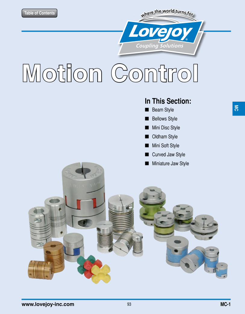
In This Section: ■ Beam Style
■ Bellows Style
■ Mini Disc Style
■ Oldham Style
■ Mini Soft Style
■ Curved Jaw Style
■ Miniature Jaw Style
Motion Control
JWJI
SC
JSF
MC
GH
PG
DD
TSP
UJ
VSD
RSL
DED
JWJIS
CJ
SFM
CG
HP
GD
DT
SPU
JVSD
RSLD
ED
Table of Contents
94 630-852-0500
When using Lovejoy products, you must follow these instructions and take the following precautions. Failure to do so may cause the power transmission product to break and parts to be thrown with sufficient force to cause severe injury or death.
Refer to this Lovejoy Catalog for proper selection, sizing, horsepower, torque range, and speed range of power transmission products, including elastomeric elements for couplings. Follow the installation instructions included with the product, and in the individual product catalogs for proper installation of power transmission products. Do not exceed catalog ratings.
During start up and operation of power transmission product, avoid sudden shock loads. Coupling assembly should operate quietly and smoothly. If coupling assembly vibrates or makes beating sound, shut down immediately, and recheck alignment. Shortly after initial operation and periodically thereafter, where applicable, inspect coupling assembly for: alignment, wear of elastomeric element, bolt torques, and flexing elements for signs of fatigue. Do not operate coupling assembly if alignment is improper, or where applicable, if elastomeric element is damaged, or worn to less than 75% of its original thickness.
Do not use any of these power transmission products for elevators, man lifts, or other devices that carry people. If the power transmission product fails, the lift device could fall resulting in severe injury or death.
For all power transmission products, you must install suitable guards in accordance with OSHA and American Society of Mechanical Engineers Standards. Do not start power transmission product before suitable guards are in place. Failure to properly guard these products may result in severe injury or death from personnel contacting moving parts or from parts being thrown from assembly in the event the power transmission product fails.
If you have any questions, contact the Lovejoy Engineering Department at 1-630-852-0500.
Safety Warning
Table of Contents
MC-2
Motion Control
JWJI
SC
JSF
MC
GH
PG
DD
TSP
UJ
VSD
RSL
DED
JWJIS
CJ
SFM
CG
HP
GD
DT
SPU
JVSD
RSLD
ED
95www.lovejoy-inc.com
Table of Contents
MC-3
Motion Control
Selection Process ..........................................................................................................................96 ....................MC-4
ASB Series > Performance / Dimensional Data ............................................................................98 ....................MC-6
ES and EC Series > Performance / Dimensional Data .................................................................99 ....................MC-7
ADB Series > Performance / Dimensional Data ..........................................................................100 ....................MC-8
BWC Series > Performance / Dimensional Data .........................................................................101 ....................MC-9
BWLC Series > Performance / Dimensional Data .......................................................................102 ..................MC-10
MDSD Series > Performance / Dimensional Data .......................................................................103 .................. MC-11
Quick Reference ..........................................................................................................................104 ..................MC-12
MD Series > Performance / Dimensional Data ............................................................................106 ..................MC-14
MDS Series > Performance / Dimensional Data .........................................................................107 ..................MC-15
MOL Series > Performance / Dimensional Data ..........................................................................108 ..................MC-16
MSF Series > Performance / Dimensional Data ..........................................................................109 ..................MC-17
GS Series > Overview ................................................................................................................. 110 ..................MC-18
GS Series > Performance Data ................................................................................................... 111 ..................MC-19
GS Series > Dimensional Data .................................................................................................... 112 ..................MC-20
GS Series > Hub Designs ........................................................................................................... 113 ..................MC-21
L Series > Performance / Dimensional Data ............................................................................... 114 ..................MC-22
Running Section Page No. Page No.
JWJI
SC
JSF
MC
GH
PG
DD
TSP
UJ
VSD
RSL
DED
JWJIS
CJ
SFM
CG
HP
GD
DT
SPU
JVSD
RSLD
ED
96 630-852-0500
Table of Contents
MC-4
Motion Control
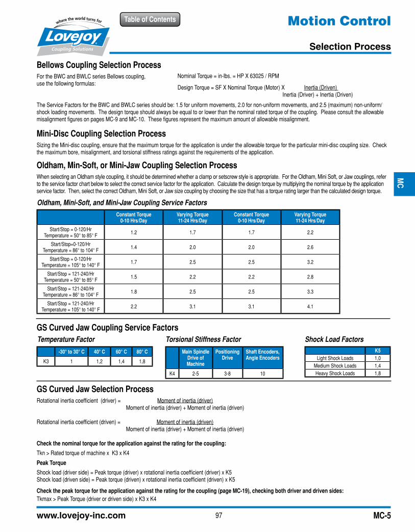
Selection Process
Motion Control Coupling Selection Process
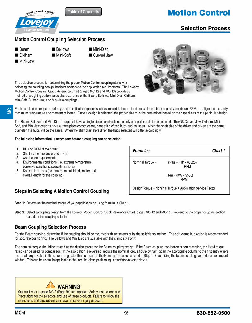
The selection process for determining the proper Motion Control coupling starts with selecting the coupling design that best addresses the application requirements. The Lovejoy Motion Control Coupling Quick Reference Chart (pages MC-12 and MC-13) provides a method of weighing performance characteristics of the Beam, Bellows, Mini-Disc, Oldham, Mini-Soft, Curved Jaw, and Mini-Jaw couplings.
Each coupling is compared side by side in critical categories such as: material, torque, torsional stiffness, bore capacity, maximum RPM, misalignment capacity, maximum temperature and moment of inertia. Once a design is selected, the proper size must be determined based on the capabilities of the particular design.
The Beam, Bellows and Mini Disc designs all have a single piece construction, so only one part needs to be selected. The GS Curved Jaw, Oldham, Mini Soft, and Mini Jaw designs have a three piece constructions, consisting of two hubs and an insert. When the shaft size of the driver and driven are the same diameter, the hubs will be the same. When the shaft diameters differ, the hubs selected will differ accordingly.
The following information is necessary before a coupling can be selected:
1. HP and RPM of the driver 2. Shaft size of the driver and driven 3. Application requirements 4. Environmental conditions (i.e. extreme temperature, corrosive conditions, space limitations) 5. Space Limitations (i.e. maximum outside diameter and overall length for the coupling)
Steps In Selecting A Motion Control Coupling
Step 1: Determine the nominal torque of your application by using formula in Chart 1.
Step 2: Select a coupling design from the Lovejoy Motion Control Quick Reference Chart (pages MC-12 and MC-13). Proceed to the proper coupling section based on the coupling selected.
Beam Coupling Selection ProcessFor the Beam coupling, determine if the coupling should be mounted with set screws or by the split/clamp method. The split clamp hub option is recommended for accurate positioning. The Bellows and Mini Disc are available with the clamp style only.
The nominal torque should be treated as the design torque for the Beam coupling design. If the Beam coupling application is non-reversing, the listed torque rating can be used for comparison. If the application is reversing, reduce the nominal torque figure by half. Scan the appropriate column to the first entry where the rated torque value in the column is greater than or equal to the Nominal Torque calculated in Step 1. Over sizing the beam coupling can reduce the amount windup. This can be useful in applications that require close positioning in start/stop/reverse drives.
Formulas Chart 1
Nominal Torque = in-lbs = (HP x 63025) RPM
Nm = (KW x 9550) RPM
Design Torque = Nominal Torque X Application Service Factor
■ Beam ■ Oldham ■ Mini-Jaw
■ Bellows ■ Mini-Soft
■ Mini-Disc ■ Curved Jaw
JWJI
SC
JSF
MC
GH
PG
DD
TSP
UJ
VSD
RSL
DED
JWJIS
CJ
SFM
CG
HP
GD
DT
SPU
JVSD
RSLD
ED
WARNINGYou must refer to page MC-2 (Page 94) for Important Safety Instructions and Precautions for the selection and use of these products. Failure to follow the instructions and precautions can result in severe injury or death.
97www.lovejoy-inc.com
Table of Contents
MC-5
Bellows Coupling Selection ProcessFor the BWC and BWLC series Bellows coupling, use the following formulas:
The Service Factors for the BWC and BWLC series should be: 1.5 for uniform movements, 2.0 for non-uniform movements, and 2.5 (maximum) non-uniform/shock loading movements. The design torque should always be equal to or lower than the nominal rated torque of the coupling. Please consult the allowable misalignment figures on pages MC-9 and MC-10. These figures represent the maximum amount of allowable misalignment.
Mini-Disc Coupling Selection ProcessSizing the Mini-disc coupling, ensure that the maximum torque for the application is under the allowable torque for the particular mini-disc coupling size. Check the maximum bore, misalignment, and torsional stiffness ratings against the requirements of the application.
Oldham, Min-Soft, or Mini-Jaw Coupling Selection ProcessWhen selecting an Oldham style coupling, it should be determined whether a clamp or setscrew style is appropriate. For the Oldham, Mini Soft, or Jaw couplings, refer to the service factor chart below to select the correct service factor for the application. Calculate the design torque by multiplying the nominal torque by the application service factor. Then, select the correct Oldham, Mini Soft, or Jaw size coupling by choosing the size that has a torque rating larger than the calculated design torque.
GS Curved Jaw Selection ProcessRotational inertia coefficient (driver) = Moment of inertia (driver) Moment of inertia (driver) + Moment of inertia (driven)
Rotational inertia coefficient (driven) = Moment of inertia (driven) Moment of inertia (driver) + Moment of inertia (driven)
Check the nominal torque for the application against the rating for the coupling:
Tkn > Rated torque of machine x K3 x K4
Peak Torque
Shock load (driver side) = Peak torque (driver) x rotational inertia coefficient (driver) x K5Shock load (driven side) = Peak torque (driven) x rotational inertia coefficient (driven) x K5
Check the peak torque for the application against the rating for the coupling (page MC-19), checking both driver and driven sides:Tkmax > Peak Torque (driver or driven side) x K3 x K4
GS Curved Jaw Coupling Service Factors
Nominal Torque = in-lbs. = HP X 63025 / RPM
Design Torque = SF X Nominal Torque (Motor) X Inertia (Driven) Inertia (Driver) + Inertia (Driven)
Oldham, Mini-Soft, and Mini-Jaw Coupling Service Factors
Constant Torque 0-10 Hrs/Day
Varying Torque 11-24 Hrs/Day
Constant Torque 0-10 Hrs/Day
Varying Torque 11-24 Hrs/Day
Start/Stop = 0-120/Hr Temperature = 50° to 85° F 1.2 1.7 1.7 2.2
Start/Stop=0-120/HrTemperature = 86° to 104° F 1.4 2.0 2.0 2.6
Start/Stop = 0-120/HrTemperature = 105° to 140° F 1.7 2.5 2.5 3.2
Start/Stop = 121-240/HrTemperature = 50° to 85° F 1.5 2.2 2.2 2.8
Start/Stop = 121-240/HrTemperature = 86° to 104° F 1.8 2.5 2.5 3.3
Start/Stop = 121-240/HrTemperature = 105° to 140° F 2.2 3.1 3.1 4.1
Temperature Factor
-30° to 30° C 40° C 60° C 80° C
K3 1 1,2 1,4 1,8
Torsional Stiffness Factor
Main Spindle Drive of Machine
Positioning Drive
Shaft Encoders, Angle Encoders
K4 2-5 3-8 10
Shock Load FactorsK5
Light Shock Loads 1,0Medium Shock Loads 1,4Heavy Shock Loads 1,8
Motion Control
Selection Process
JWJI
SC
JSF
MC
GH
PG
DD
TSP
UJ
VSD
RSL
DED
JWJIS
CJ
SFM
CG
HP
GD
DT
SPU
JVSD
RSLD
ED
98 630-852-0500
Table of Contents
MC-6
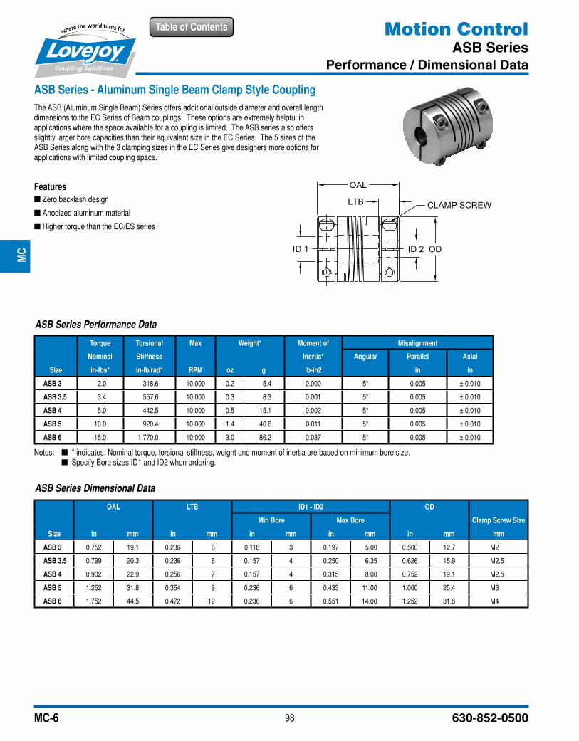
ASB Series - Aluminum Single Beam Clamp Style CouplingThe ASB (Aluminum Single Beam) Series offers additional outside diameter and overall length dimensions to the EC Series of Beam couplings. These options are extremely helpful in applications where the space available for a coupling is limited. The ASB series also offers slightly larger bore capacities than their equivalent size in the EC Series. The 5 sizes of the ASB Series along with the 3 clamping sizes in the EC Series give designers more options for applications with limited coupling space.
Features ■ Zero backlash design
■ Anodized aluminum material
■ Higher torque than the EC/ES series
Motion ControlASB Series
Performance / Dimensional Data
ASB Series Dimensional Data
OAL LTB ID1 - ID2 OD
Min Bore Max Bore Clamp Screw Size
Size in mm in mm in mm in mm in mm mm
ASB 3 0.752 19.1 0.236 6 0.118 3 0.197 5.00 0.500 12.7 M2
ASB 3.5 0.799 20.3 0.236 6 0.157 4 0.250 6.35 0.626 15.9 M2.5
ASB 4 0.902 22.9 0.256 7 0.157 4 0.315 8.00 0.752 19.1 M2.5
ASB 5 1.252 31.8 0.354 9 0.236 6 0.433 11.00 1.000 25.4 M3
ASB 6 1.752 44.5 0.472 12 0.236 6 0.551 14.00 1.252 31.8 M4
ASB Series Performance Data
Torque Torsional Max Weight* Moment of Misalignment
Nominal Stiffness Inertia* Angular Parallel Axial
Size in-lbs* in-lb/rad* RPM oz g lb-in2 in in
ASB 3 2.0 318.6 10,000 0.2 5.4 0.000 5° 0.005 ± 0.010
ASB 3.5 3.4 557.6 10,000 0.3 8.3 0.001 5° 0.005 ± 0.010
ASB 4 5.0 442.5 10,000 0.5 15.1 0.002 5° 0.005 ± 0.010
ASB 5 10.0 920.4 10,000 1.4 40.6 0.011 5° 0.005 ± 0.010
ASB 6 15.0 1,770.0 10,000 3.0 86.2 0.037 5° 0.005 ± 0.010
Notes: n * indicates: Nominal torque, torsional stiffness, weight and moment of inertia are based on minimum bore size. n Specify Bore sizes ID1 and ID2 when ordering.
JWJI
SC
JSF
MC
GH
PG
DD
TSP
UJ
VSD
RSL
DED
JWJIS
CJ
SFM
CG
HP
GD
DT
SPU
JVSD
RSLD
ED
99www.lovejoy-inc.com
Table of Contents
MC-7
Motion ControlES and EC Series
Performance / Dimensional Data
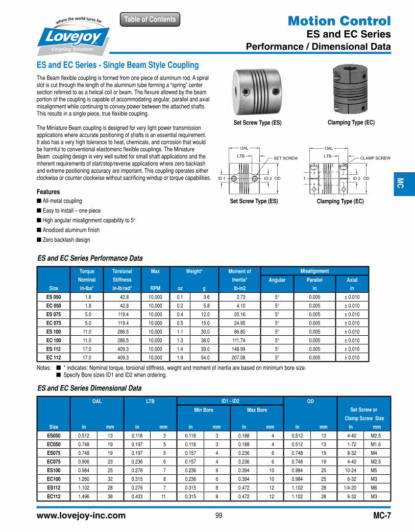
ES and EC Series - Single Beam Style CouplingThe Beam flexible coupling is formed from one piece of aluminum rod. A spiral slot is cut through the length of the aluminum tube forming a “spring” center section referred to as a helical coil or beam. The flexure allowed by the beam portion of the coupling is capable of accommodating angular, parallel and axial misalignment while continuing to convey power between the attached shafts. This results in a single piece, true flexible coupling.
The Miniature Beam coupling is designed for very light power transmission applications where accurate positioning of shafts is an essential requirement. It also has a very high tolerance to heat, chemicals, and corrosion that would be harmful to conventional elastomeric flexible couplings. The Miniature Beam coupling design is very well suited for small shaft applications and the inherent requirements of start/stop/reverse applications where zero backlash and extreme positioning accuracy are important. This coupling operates either clockwise or counter clockwise without sacrificing windup or torque capabilities.
Features ■ All-metal coupling
■ Easy to install – one piece
■ High angular misalignment capability to 5°
■ Anodized aluminum finish
■ Zero backlash design
Clamping Type (EC)
Set Screw Type (ES)
Set Screw Type (ES)
Clamping Type (EC)
Notes: n * indicates: Nominal torque, torsional stiffness, weight and moment of inertia are based on minimum bore size. n Specify Bore sizes ID1 and ID2 when ordering.
ES and EC Series Dimensional Data
OAL LTB ID1 - ID2 OD
Min Bore Max Bore Set Screw or
Clamp Screw Size
Size in mm in mm in mm in mm in mm in mm
ES050 0.512 13 0.118 3 0.118 3 0.188 4 0.512 13 4-40 M2.5
EC050 0.748 19 0.197 5 0.118 3 0.188 4 0.512 13 1-72 M1.6
ES075 0.748 19 0.197 5 0.157 4 0.236 6 0.748 19 8-32 M4
EC075 0.906 23 0.236 6 0.157 4 0.236 6 0.748 19 4-40 M2.5
ES100 0.984 25 0.276 7 0.236 6 0.394 10 0.984 25 10-24 M5
EC100 1.260 32 0.315 8 0.236 6 0.394 10 0.984 25 6-32 M3
ES112 1.102 28 0.276 7 0.315 8 0.472 12 1.102 28 1/4-20 M6
EC112 1.496 38 0.433 11 0.315 8 0.472 12 1.102 28 6-32 M3
ES and EC Series Performance Data
Torque Torsional Max Weight* Moment of Misalignment
Nominal Stiffness Inertia* Angular Parallel Axial
Size in-lbs* in-lb/rad* RPM oz g lb-in2 in in
ES 050 1.8 42.8 10,000 0.1 3.6 2.73 5° 0.005 ± 0.010
EC 050 1.8 42.8 10,000 0.2 5.8 4.10 5° 0.005 ± 0.010
ES 075 5.0 119.4 10,000 0.4 12.0 20.16 5° 0.005 ± 0.010
EC 075 5.0 119.4 10,000 0.5 15.0 24.95 5° 0.005 ± 0.010
ES 100 11.0 286.5 10,000 1.1 30.0 86.80 5° 0.005 ± 0.010
EC 100 11.0 286.5 10,000 1.3 38.0 111.74 5° 0.005 ± 0.010
ES 112 17.0 409.3 10,000 1.4 39.0 148.99 5° 0.005 ± 0.010
EC 112 17.0 409.3 10,000 1.9 54.0 207.08 5° 0.005 ± 0.010JW
JIS
CJ
SFM
CG
HP
GD
DT
SPU
JVS
DR
SLD
ED
JWJIS
CJ
SFM
CG
HP
GD
DT
SPU
JVSD
RSLD
ED
100 630-852-0500
Table of Contents
MC-8
Motion ControlADB Series
Performance / Dimensional Data
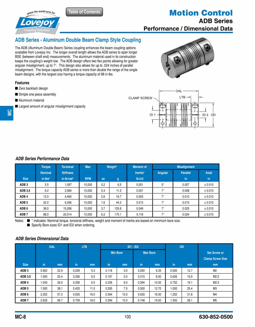
ADB Series - Aluminum Double Beam Clamp Style CouplingThe ADB (Aluminum Double Beam) Series coupling enhances the beam coupling options available from Lovejoy Inc. The longer overall length allows the ADB series to span longer BSE (between shaft end) measurements. The aluminum material used in its construction keeps the coupling’s weight low. The ADB design offers two flex points allowing for greater angular misalignment, up to 7°. This design also allows for up to .024 inches of parallel misalignment. The torque capacity ADB series is more than double the range of the single beam designs, with the largest size having a torque capacity of 88 in-lbs.
Features ■ Zero backlash design
■ Simple one piece assembly
■ Aluminum material
■ Largest amount of angular misalignment capacity
Notes: n * indicates: Nominal torque, torsional stiffness, weight and moment of inertia are based on minimum bore size. n Specify Bore sizes ID1 and ID2 when ordering.
ADB Series Performance Data
Torque Torsional Max Weight* Moment of Misalignment
Nominal Stiffness Inertia* Angular Parallel Axial
Size in-lbs* in-lb/rad* RPM oz g lb-in2 in in
ADB 3 3.5 1,097 10,000 0.2 6.5 0.001 5° 0.007 ± 0.010
ADB 3.5 6.2 2,584 10,000 0.4 11.5 0.001 7° 0.008 ± 0.010
ADB 4 12.0 4,460 10,000 0.6 16.7 0.003 7° 0.010 ± 0.010
ADB 5 20.0 6,266 10,000 1.6 44.3 0.013 7° 0.015 ± 0.010
ADB 6 38.0 15,266 10,000 3.7 105.8 0.049 7° 0.020 ± 0.010
ADB 7 88.0 20,514 10,000 6.2 175.1 0.118 7° 0.024 ± 0.010
ADB Series Dimensional Data
OAL LTB ID1 - ID2 OD
Min Bore Max Bore Set Screw or
Clamp Screw Size
Size in mm in mm in mm in mm in mm mm
ADB 3 0.902 22.9 0.209 5.3 0.118 3.0 0.250 6.35 0.500 12.7 M2
ADB 3.5 1.000 25.4 0.256 6.5 0.197 5.0 0.315 8.00 0.626 15.9 M2.5
ADB 4 1.043 26.5 0.256 6.5 0.236 6.0 0.394 10.00 0.752 19.1 M2.5
ADB 5 1.500 38.1 0.433 11.0 0.295 7.5 0.500 12.70 1.000 25.4 M3
ADB 6 2.252 57.2 0.630 16.0 0.394 10.0 0.630 16.00 1.252 31.8 M4
ADB 7 2.626 66.7 0.709 18.0 0.394 10.0 0.748 19.00 1.500 38.1 M5
JWJI
SC
JSF
MC
GH
PG
DD
TSP
UJ
VSD
RSL
DED
JWJIS
CJ
SFM
CG
HP
GD
DT
SPU
JVSD
RSLD
ED
101www.lovejoy-inc.com
Table of Contents
MC-9
Motion ControlBWC Series
Performance / Dimensional Data
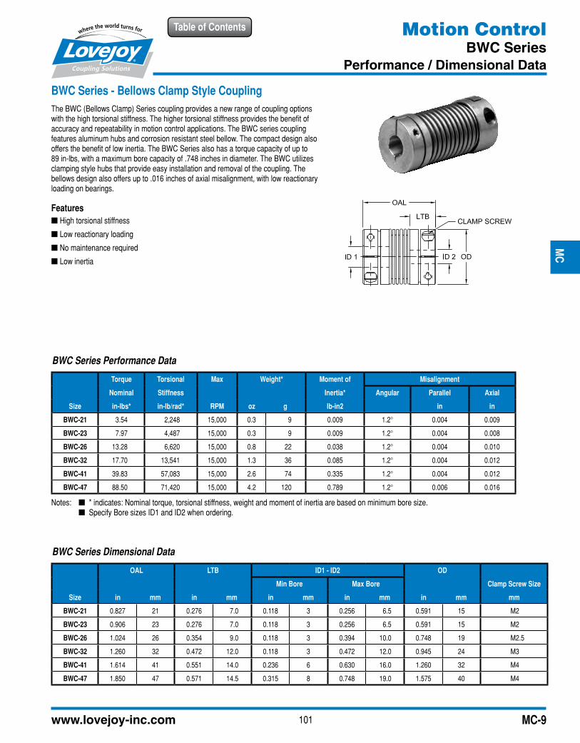
BWC Series - Bellows Clamp Style CouplingThe BWC (Bellows Clamp) Series coupling provides a new range of coupling options with the high torsional stiffness. The higher torsional stiffness provides the benefit of accuracy and repeatability in motion control applications. The BWC series coupling features aluminum hubs and corrosion resistant steel bellow. The compact design also offers the benefit of low inertia. The BWC Series also has a torque capacity of up to 89 in-lbs, with a maximum bore capacity of .748 inches in diameter. The BWC utilizes clamping style hubs that provide easy installation and removal of the coupling. The bellows design also offers up to .016 inches of axial misalignment, with low reactionary loading on bearings.
Features ■ High torsional stiffness
■ Low reactionary loading
■ No maintenance required
■ Low inertia
BWC Series Dimensional Data
OAL LTB ID1 - ID2 OD
Min Bore Max Bore Clamp Screw Size
Size in mm in mm in mm in mm in mm mm
BWC-21 0.827 21 0.276 7.0 0.118 3 0.256 6.5 0.591 15 M2
BWC-23 0.906 23 0.276 7.0 0.118 3 0.256 6.5 0.591 15 M2
BWC-26 1.024 26 0.354 9.0 0.118 3 0.394 10.0 0.748 19 M2.5
BWC-32 1.260 32 0.472 12.0 0.118 3 0.472 12.0 0.945 24 M3
BWC-41 1.614 41 0.551 14.0 0.236 6 0.630 16.0 1.260 32 M4
BWC-47 1.850 47 0.571 14.5 0.315 8 0.748 19.0 1.575 40 M4
BWC Series Performance Data
Torque Torsional Max Weight* Moment of Misalignment
Nominal Stiffness Inertia* Angular Parallel Axial
Size in-lbs* in-lb/rad* RPM oz g lb-in2 in in
BWC-21 3.54 2,248 15,000 0.3 9 0.009 1.2° 0.004 0.009
BWC-23 7.97 4,487 15,000 0.3 9 0.009 1.2° 0.004 0.008
BWC-26 13.28 6,620 15,000 0.8 22 0.038 1.2° 0.004 0.010
BWC-32 17.70 13,541 15,000 1.3 36 0.085 1.2° 0.004 0.012
BWC-41 39.83 57,083 15,000 2.6 74 0.335 1.2° 0.004 0.012
BWC-47 88.50 71,420 15,000 4.2 120 0.789 1.2° 0.006 0.016
Notes: n * indicates: Nominal torque, torsional stiffness, weight and moment of inertia are based on minimum bore size. n Specify Bore sizes ID1 and ID2 when ordering.
JWJI
SC
JSF
MC
GH
PG
DD
TSP
UJ
VSD
RSL
DED
JWJIS
CJ
SFM
CG
HP
GD
DT
SPU
JVSD
RSLD
ED
102 630-852-0500
Table of Contents
MC-10
Motion ControlBWLC Series
Performance / Dimensional Data
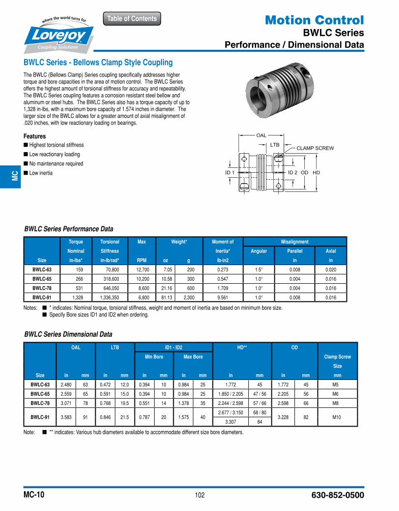
BWLC Series - Bellows Clamp Style CouplingThe BWLC (Bellows Clamp) Series coupling specifically addresses higher torque and bore capacities in the area of motion control. The BWLC Series offers the highest amount of torsional stiffness for accuracy and repeatability. The BWLC Series coupling features a corrosion resistant steel bellow and aluminum or steel hubs. The BWLC Series also has a torque capacity of up to 1,328 in-lbs, with a maximum bore capacity of 1.574 inches in diameter. The larger size of the BWLC allows for a greater amount of axial misalignment of .020 inches, with low reactionary loading on bearings.
Features ■ Highest torsional stiffness
■ Low reactionary loading
■ No maintenance required
■ Low inertia
BWLC Series Dimensional Data
OAL LTB ID1 - ID2 HD** OD
Min Bore Max Bore Clamp Screw
Size
Size in mm in mm in mm in mm in mm in mm mm
BWLC-63 2.480 63 0.472 12.0 0.394 10 0.984 25 1.772 45 1.772 45 M5
BWLC-65 2.559 65 0.591 15.0 0.394 10 0.984 25 1.850 / 2.205 47 / 56 2.205 56 M6
BWLC-78 3.071 78 0.768 19.5 0.551 14 1.378 35 2.244 / 2.598 57 / 66 2.598 66 M8
BWLC-91 3.583 91 0.846 21.5 0.787 20 1.575 402.677 / 3.150 68 / 80
3.228 82 M103.307 84
Note: n ** indicates: Various hub diameters available to accommodate different size bore diameters.
BWLC Series Performance Data
Torque Torsional Max Weight* Moment of Misalignment
Nominal Stiffness Inertia* Angular Parallel Axial
Size in-lbs* in-lb/rad* RPM oz g lb-in2 in in
BWLC-63 159 70,800 12,700 7.05 200 0.273 1.5° 0.008 0.020
BWLC-65 266 318,600 10,200 10.58 300 0.547 1.0° 0.004 0.016
BWLC-78 531 646,050 8,600 21.16 600 1.709 1.0° 0.004 0.016
BWLC-91 1,328 1,336,350 6,800 81.13 2,300 9.561 1.0° 0.008 0.016
Notes: n * indicates: Nominal torque, torsional stiffness, weight and moment of inertia are based on minimum bore size. n Specify Bore sizes ID1 and ID2 when ordering.
JWJI
SC
JSF
MC
GH
PG
DD
TSP
UJ
VSD
RSL
DED
JWJIS
CJ
SFM
CG
HP
GD
DT
SPU
JVSD
RSLD
ED
103www.lovejoy-inc.com
Table of Contents
MC-11
Motion ControlMDSD Series
Performance / Dimensional Data
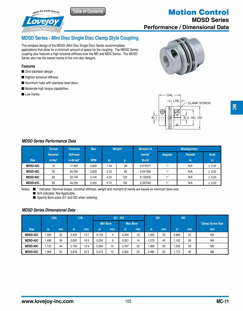
MDSD Series - Mini Disc Single Disc Clamp Style CouplingThe compact design of the MDSD (Mini Disc Single Disc) Series accommodates applications that allow for a minimum amount of space for the coupling. The MDSD Series coupling also features a high torsional stiffness over the MD and MDS Series. The MDSD Series also has the lowest inertia of the mini disc designs.
Features ■ Zero backlash design
■ Highest torsional stiffness
■ Aluminum hubs with stainless steel discs
■ Moderate-high torque capabilities
■ Low Inertia
MDSD Series Dimensional Data
OAL LTB ID1 - ID2 OD HD
Min Bore Max Bore Clamp Screw Size
Size in mm in mm in mm in mm in mm in mm mm
MDSD-32C 1.260 32 0.539 13.7 0.118 4 0.394 10 1.260 32 0.866 22 M3
MDSD-40C 1.496 38 0.650 16.5 0.236 6 0.551 14 1.575 40 1.102 28 M4
MDSD-50C 1.732 44 0.764 19.4 0.394 10 0.787 20 1.969 50 1.535 39 M5
MDSD-63C 1.969 50 0.878 22.3 0.472 12 0.984 25 2.480 63 1.772 45 M6
MDSD Series Performance Data
Torque Torsional Max Weight* Moment of Misalignment
Nominal Stiffness Inertia* Angular Parallel Axial
Size in-lbs* in-lb/rad* RPM oz g lb-in2 in in
MDSD-32C 18 11,505 4,800 1.34 38 0.015377 1° N/A ± 0.20
MDSD-40C 35 24,780 3,800 2.33 66 0.041006 1° N/A ± 0.20
MDSD-50C 66 32,745 3,100 4.23 120 0.126435 1° N/A ± 0.20
MDSD-63C 89 44,250 2,400 6.70 190 0.287042 1° N/A ± 0.20
Notes: n * indicates: Nominal torque, torsional stiffness, weight and moment of inertia are based on minimum bore size. n N/A indicates: Not Applicable. n Specify Bore sizes ID1 and ID2 when ordering.
JWJI
SC
JSF
MC
GH
PG
DD
TSP
UJ
VSD
RSL
DED
JWJIS
CJ
SFM
CG
HP
GD
DT
SPU
JVSD
RSLD
ED
104 630-852-0500
Table of Contents
MC-12
Motion Control
Quick Reference
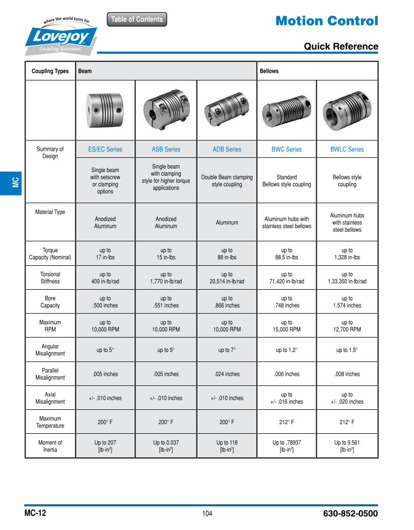
Coupling Types Beam Bellows
Summary of Design
ES/EC Series ASB Series ADB Series BWC Series BWLC Series
Single beam with setscrew or clamping
options
Single beam with clamping
style for higher torque applications
Double Beam clamping style coupling
Standard Bellows style coupling
Bellows style coupling
Material TypeAnodized Aluminum
Anodized Aluminum
AluminumAluminum hubs with
stainless steel bellows
Aluminum hubs with stainless steel bellows
Torque Capacity (Nominal)
up to 17 in-lbs
up to 15 in-lbs
up to 88 in-lbs
up to 88.5 in-lbs
up to 1,328 in-lbs
Torsional Stiffness
up to 409 in-lb/rad
up to 1,770 in-lb/rad
up to 20,514 in-lb/rad
up to 71,420 in-lb/rad
up to 1,33,350 in-lb/rad
Bore Capacity
up to .500 inches
up to .551 inches
up to .866 inches
up to .748 inches
up to 1.574 inches
Maximum RPM
up to 10,000 RPM
up to 10,000 RPM
up to10,000 RPM
up to 15,000 RPM
up to 12,700 RPM
Angular Misalignment
up to 5° up to 5° up to 7° up to 1.2° up to 1.5°
Parallel Misalignment
.005 inches .005 inches .024 inches .006 inches .008 inches
Axial Misalignment
+/- .010 inches +/- .010 inches +/- .010 inchesup to
+/- .016 inchesup to
+/- .020 inches
Maximum Temperature
200° F 200° F 200° F 212° F 212° F
Moment of Inertia
Up to 207[lb-in2]
Up to 0.037[lb-in2]
Up to 118[lb-in2]
Up to .78937[lb-in2]
Up to 9.561[lb-in2]
JWJI
SC
JSF
MC
GH
PG
DD
TSP
UJ
VSD
RSL
DED
JWJIS
CJ
SFM
CG
HP
GD
DT
SPU
JVSD
RSLD
ED
105www.lovejoy-inc.com
Table of Contents
MC-13
Motion Control
Quick Reference
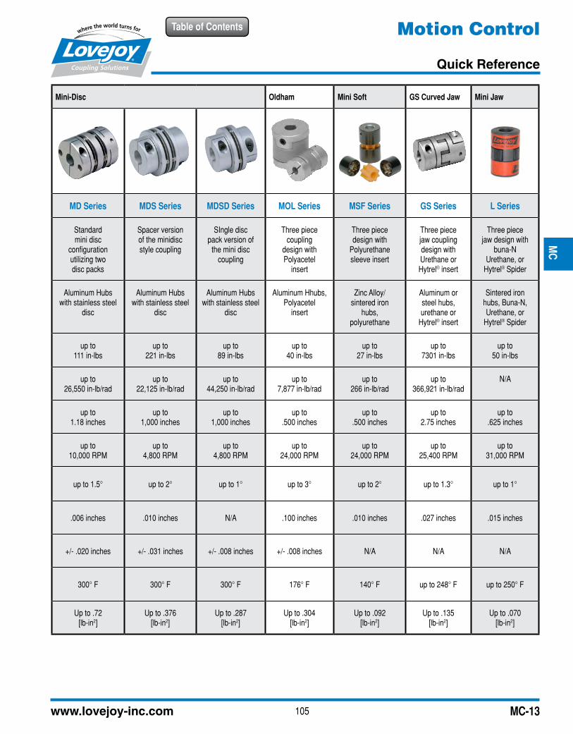
Mini-Disc Oldham Mini Soft GS Curved Jaw Mini Jaw
MD Series MDS Series MDSD Series MOL Series MSF Series GS Series L Series
Standard mini disc
configurationutilizing twodisc packs
Spacer versionof the minidiscstyle coupling
SIngle discpack version of
the mini disccoupling
Three piececoupling
design withPolyacetel
insert
Three piecedesign with
Polyurethanesleeve insert
Three piecejaw couplingdesign withUrethane orHytrel® insert
Three piecejaw design with
buna-NUrethane, or
Hytrel® Spider
Aluminum Hubswith stainless steel
disc
Aluminum Hubswith stainless steel
disc
Aluminum Hubswith stainless steel
disc
Aluminum Hhubs,Polyacetel
insert
Zinc Alloy/sintered iron
hubs,polyurethane
Aluminum orsteel hubs,urethane or
Hytrel® insert
Sintered ironhubs, Buna-N,Urethane, or
Hytrel® Spider
up to 111 in-lbs
up to 221 in-lbs
up to 89 in-lbs
up to 40 in-lbs
up to 27 in-lbs
up to7301 in-lbs
up to50 in-lbs
up to 26,550 in-lb/rad
up to 22,125 in-lb/rad
up to 44,250 in-lb/rad
up to 7,877 in-lb/rad
up to 266 in-lb/rad
up to366,921 in-lb/rad
N/A
up to1.18 inches
up to1,000 inches
up to1,000 inches
up to.500 inches
up to.500 inches
up to2.75 inches
up to.625 inches
up to10,000 RPM
up to4,800 RPM
up to 4,800 RPM
up to24,000 RPM
up to24,000 RPM
up to25,400 RPM
up to31,000 RPM
up to 1.5° up to 2° up to 1° up to 3° up to 2° up to 1.3° up to 1°
.006 inches .010 inches N/A .100 inches .010 inches .027 inches .015 inches
+/- .020 inches +/- .031 inches +/- .008 inches +/- .008 inches N/A N/A N/A
300° F 300° F 300° F 176° F 140° F up to 248° F up to 250° F
Up to .72[lb-in2]
Up to .376[lb-in2]
Up to .287[lb-in2]
Up to .304[lb-in2]
Up to .092[lb-in2]
Up to .135[lb-in2]
Up to .070[lb-in2]
JWJI
SC
JSF
MC
GH
PG
DD
TSP
UJ
VSD
RSL
DED
JWJIS
CJ
SFM
CG
HP
GD
DT
SPU
JVSD
RSLD
ED
106 630-852-0500
Table of Contents
MC-14
Motion ControlMD Series
Performance / Dimensional Data
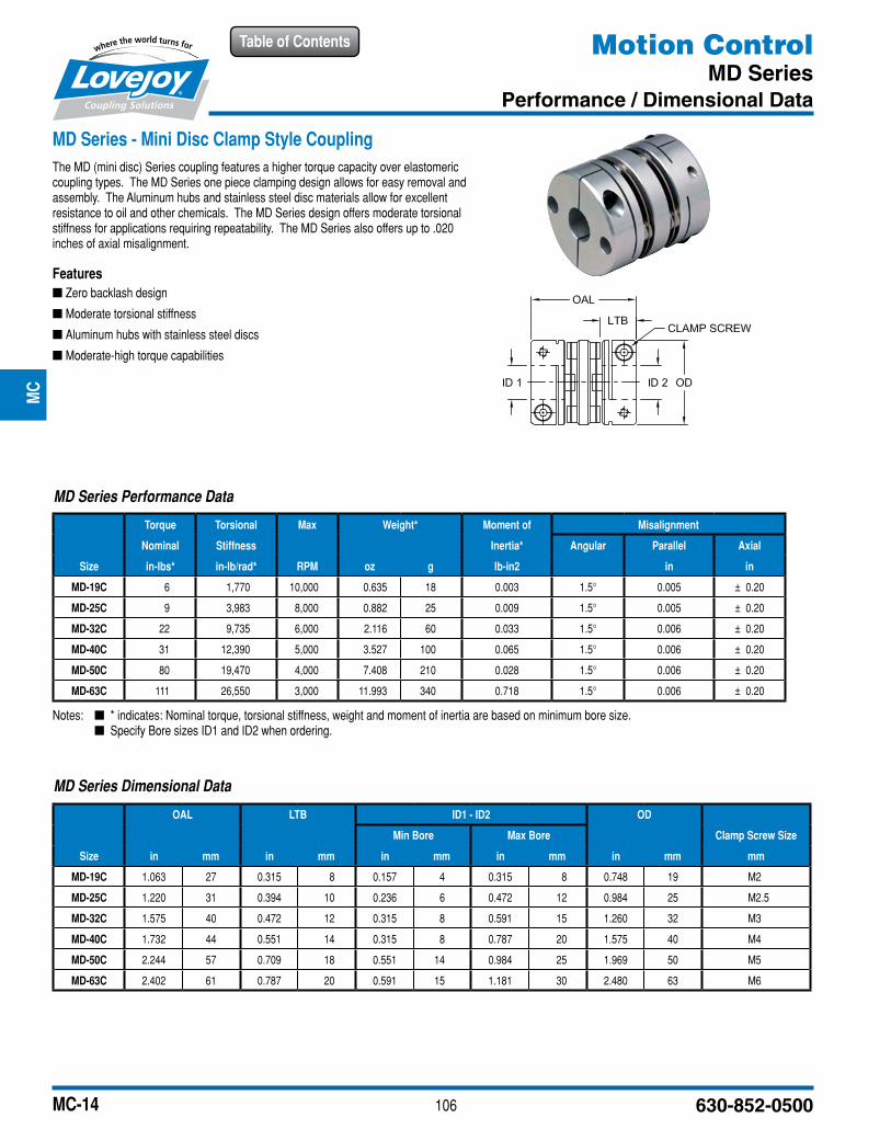
MD Series - Mini Disc Clamp Style CouplingThe MD (mini disc) Series coupling features a higher torque capacity over elastomeric coupling types. The MD Series one piece clamping design allows for easy removal and assembly. The Aluminum hubs and stainless steel disc materials allow for excellent resistance to oil and other chemicals. The MD Series design offers moderate torsional stiffness for applications requiring repeatability. The MD Series also offers up to .020 inches of axial misalignment.
Features ■ Zero backlash design
■ Moderate torsional stiffness
■ Aluminum hubs with stainless steel discs
■ Moderate-high torque capabilities
MD Series Dimensional Data
OAL LTB ID1 - ID2 OD
Min Bore Max Bore Clamp Screw Size
Size in mm in mm in mm in mm in mm mm
MD-19C 1.063 27 0.315 8 0.157 4 0.315 8 0.748 19 M2
MD-25C 1.220 31 0.394 10 0.236 6 0.472 12 0.984 25 M2.5
MD-32C 1.575 40 0.472 12 0.315 8 0.591 15 1.260 32 M3
MD-40C 1.732 44 0.551 14 0.315 8 0.787 20 1.575 40 M4
MD-50C 2.244 57 0.709 18 0.551 14 0.984 25 1.969 50 M5
MD-63C 2.402 61 0.787 20 0.591 15 1.181 30 2.480 63 M6
MD Series Performance Data
Torque Torsional Max Weight* Moment of Misalignment
Nominal Stiffness Inertia* Angular Parallel Axial
Size in-lbs* in-lb/rad* RPM oz g lb-in2 in in
MD-19C 6 1,770 10,000 0.635 18 0.003 1.5° 0.005 ± 0.20
MD-25C 9 3,983 8,000 0.882 25 0.009 1.5° 0.005 ± 0.20
MD-32C 22 9,735 6,000 2.116 60 0.033 1.5° 0.006 ± 0.20
MD-40C 31 12,390 5,000 3.527 100 0.065 1.5° 0.006 ± 0.20
MD-50C 80 19,470 4,000 7.408 210 0.028 1.5° 0.006 ± 0.20
MD-63C 111 26,550 3,000 11.993 340 0.718 1.5° 0.006 ± 0.20
Notes: n * indicates: Nominal torque, torsional stiffness, weight and moment of inertia are based on minimum bore size. n Specify Bore sizes ID1 and ID2 when ordering.
JWJI
SC
JSF
MC
GH
PG
DD
TSP
UJ
VSD
RSL
DED
JWJIS
CJ
SFM
CG
HP
GD
DT
SPU
JVSD
RSLD
ED

107www.lovejoy-inc.com
Table of Contents
MC-15
Motion ControlMDS Series
Performance / Dimensional Data
MDS Series – Mini Disc Spacer Clamp Style CouplingThe MDS (mini disc spacer) Series coupling features a higher parallel misalignment capacity over standard MD Series at .006 inches. The MDS Series also has the highest parallel misalignment at .012 inches and angular misalignment at 2° of any of the mini disc couplings.
Features ■ Zero backlash design
■ High torsional stiffness
■ Aluminum hubs with stainless steel discs
■ Moderate-high torque capabilities
■ Low Inertia
MDS Series Dimensional Data
OAL LTB ID1 - ID2 OD HD
Min Bore Max Bore Clamp Screw Size
Size in mm in mm in mm in mm in mm in mm mm
MDS-32C 1.575 40 0.539 13.7 0.236 6 0.394 10 1.260 32 0.866 22 M3
MDS-40C 1.811 46 0.650 16.5 0.315 8 0.551 14 1.575 40 1.102 28 M4
MDS-50C 2.047 52 0.764 19.4 0.472 12 0.787 20 1.969 50 1.535 39 M5
MDS-63C 2.283 58 0.878 22.3 0.591 15 0.984 25 2.480 63 1.772 45 M6
MDS Series Performance Data
Torque Torsional Max Weight* Moment of Misalignment
Nominal Stiffness Inertia* Angular Parallel Axial
Size in-lbs* in-lb/rad* RPM oz g lb-in2 in in
MDS-32C 18 8,850 4,800 1.69 48 0.212 2° 0.006 ± 0.016
MDS-40C 35 13,275 3,800 2.86 81 0.055 2° 0.007 ± 0.016
MDS-50C 66 17,700 3,100 5.29 150 0.157 2° 0.007 ± 0.024
MDS-63C 89 22,125 2,400 8.11 230 0.376 2° 0.012 ± 0.031
Notes: n * indicates: Nominal torque, torsional stiffness, weight and moment of inertia are based on minimum bore size. n Specify Bore sizes ID1 and ID2 when ordering.
JWJI
SC
JSF
MC
GH
PG
DD
TSP
UJ
VSD
RSL
DED
JWJIS
CJ
SFM
CG
HP
GD
DT
SPU
JVSD
RSLD
ED
108 630-852-0500
Table of Contents
MC-16
Motion ControlMOL Series
Performance / Dimensional Data
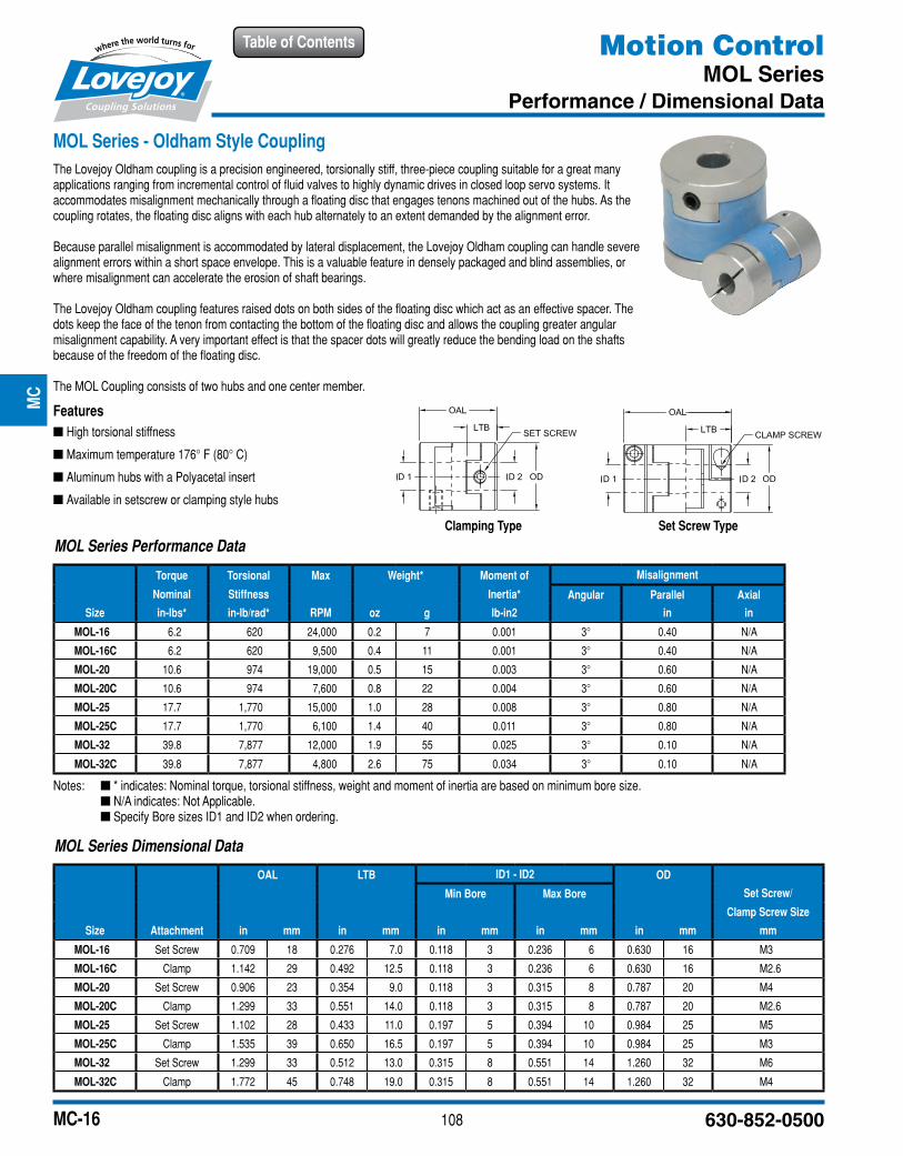
MOL Series - Oldham Style CouplingThe Lovejoy Oldham coupling is a precision engineered, torsionally stiff, three-piece coupling suitable for a great many applications ranging from incremental control of fluid valves to highly dynamic drives in closed loop servo systems. It accommodates misalignment mechanically through a floating disc that engages tenons machined out of the hubs. As the coupling rotates, the floating disc aligns with each hub alternately to an extent demanded by the alignment error.
Because parallel misalignment is accommodated by lateral displacement, the Lovejoy Oldham coupling can handle severe alignment errors within a short space envelope. This is a valuable feature in densely packaged and blind assemblies, or where misalignment can accelerate the erosion of shaft bearings.
The Lovejoy Oldham coupling features raised dots on both sides of the floating disc which act as an effective spacer. The dots keep the face of the tenon from contacting the bottom of the floating disc and allows the coupling greater angular misalignment capability. A very important effect is that the spacer dots will greatly reduce the bending load on the shafts because of the freedom of the floating disc.
The MOL Coupling consists of two hubs and one center member.
Features ■ High torsional stiffness
■ Maximum temperature 176° F (80° C)
■ Aluminum hubs with a Polyacetal insert
■ Available in setscrew or clamping style hubs
Clamping Type Set Screw Type
Notes: n * indicates: Nominal torque, torsional stiffness, weight and moment of inertia are based on minimum bore size. n N/A indicates: Not Applicable. n Specify Bore sizes ID1 and ID2 when ordering.
MOL Series Dimensional Data
OAL LTB ID1 - ID2 OD
Min Bore Max Bore Set Screw/
Clamp Screw Size
Size Attachment in mm in mm in mm in mm in mm mm
MOL-16 Set Screw 0.709 18 0.276 7.0 0.118 3 0.236 6 0.630 16 M3
MOL-16C Clamp 1.142 29 0.492 12.5 0.118 3 0.236 6 0.630 16 M2.6
MOL-20 Set Screw 0.906 23 0.354 9.0 0.118 3 0.315 8 0.787 20 M4
MOL-20C Clamp 1.299 33 0.551 14.0 0.118 3 0.315 8 0.787 20 M2.6
MOL-25 Set Screw 1.102 28 0.433 11.0 0.197 5 0.394 10 0.984 25 M5
MOL-25C Clamp 1.535 39 0.650 16.5 0.197 5 0.394 10 0.984 25 M3
MOL-32 Set Screw 1.299 33 0.512 13.0 0.315 8 0.551 14 1.260 32 M6
MOL-32C Clamp 1.772 45 0.748 19.0 0.315 8 0.551 14 1.260 32 M4
MOL Series Performance Data
Torque Torsional Max Weight* Moment of Misalignment
Nominal Stiffness Inertia* Angular Parallel Axial
Size in-lbs* in-lb/rad* RPM oz g lb-in2 in in
MOL-16 6.2 620 24,000 0.2 7 0.001 3° 0.40 N/A
MOL-16C 6.2 620 9,500 0.4 11 0.001 3° 0.40 N/A
MOL-20 10.6 974 19,000 0.5 15 0.003 3° 0.60 N/A
MOL-20C 10.6 974 7,600 0.8 22 0.004 3° 0.60 N/A
MOL-25 17.7 1,770 15,000 1.0 28 0.008 3° 0.80 N/A
MOL-25C 17.7 1,770 6,100 1.4 40 0.011 3° 0.80 N/A
MOL-32 39.8 7,877 12,000 1.9 55 0.025 3° 0.10 N/A
MOL-32C 39.8 7,877 4,800 2.6 75 0.034 3° 0.10 N/A
JWJI
SC
JSF
MC
GH
PG
DD
TSP
UJ
VSD
RSL
DED
JWJIS
CJ
SFM
CG
HP
GD
DT
SPU
JVSD
RSLD
ED
109www.lovejoy-inc.com
Table of Contents
MC-17
Motion ControlMSF Series
Performance / Dimensional Data
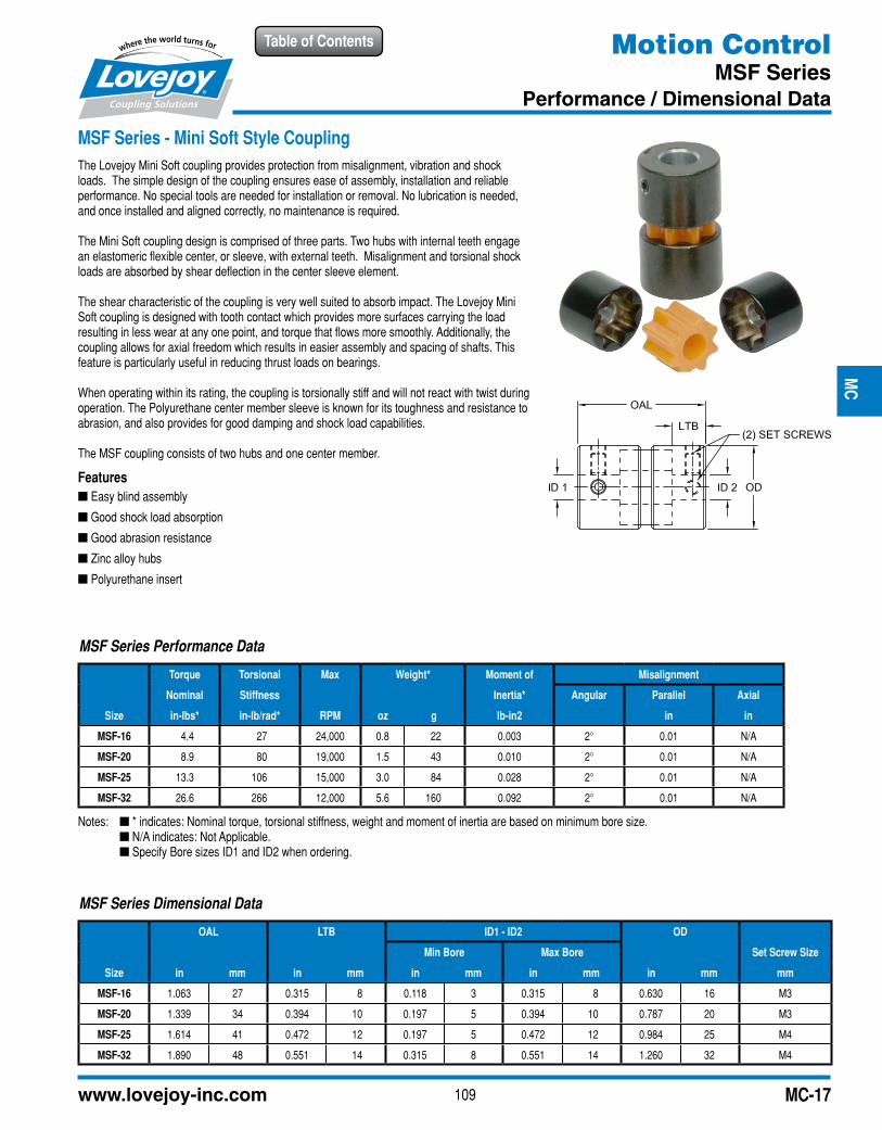
MSF Series - Mini Soft Style CouplingThe Lovejoy Mini Soft coupling provides protection from misalignment, vibration and shock loads. The simple design of the coupling ensures ease of assembly, installation and reliable performance. No special tools are needed for installation or removal. No lubrication is needed, and once installed and aligned correctly, no maintenance is required.
The Mini Soft coupling design is comprised of three parts. Two hubs with internal teeth engage an elastomeric flexible center, or sleeve, with external teeth. Misalignment and torsional shock loads are absorbed by shear deflection in the center sleeve element.
The shear characteristic of the coupling is very well suited to absorb impact. The Lovejoy Mini Soft coupling is designed with tooth contact which provides more surfaces carrying the load resulting in less wear at any one point, and torque that flows more smoothly. Additionally, the coupling allows for axial freedom which results in easier assembly and spacing of shafts. This feature is particularly useful in reducing thrust loads on bearings.
When operating within its rating, the coupling is torsionally stiff and will not react with twist during operation. The Polyurethane center member sleeve is known for its toughness and resistance to abrasion, and also provides for good damping and shock load capabilities.
The MSF coupling consists of two hubs and one center member.
Features ■ Easy blind assembly
■ Good shock load absorption
■ Good abrasion resistance
■ Zinc alloy hubs
■ Polyurethane insert
Notes: n * indicates: Nominal torque, torsional stiffness, weight and moment of inertia are based on minimum bore size. n N/A indicates: Not Applicable. n Specify Bore sizes ID1 and ID2 when ordering.
MSF Series Dimensional Data
OAL LTB ID1 - ID2 OD
Min Bore Max Bore Set Screw Size
Size in mm in mm in mm in mm in mm mm
MSF-16 1.063 27 0.315 8 0.118 3 0.315 8 0.630 16 M3
MSF-20 1.339 34 0.394 10 0.197 5 0.394 10 0.787 20 M3
MSF-25 1.614 41 0.472 12 0.197 5 0.472 12 0.984 25 M4
MSF-32 1.890 48 0.551 14 0.315 8 0.551 14 1.260 32 M4
MSF Series Performance Data
Torque Torsional Max Weight* Moment of Misalignment
Nominal Stiffness Inertia* Angular Parallel Axial
Size in-lbs* in-lb/rad* RPM oz g lb-in2 in in
MSF-16 4.4 27 24,000 0.8 22 0.003 2° 0.01 N/A
MSF-20 8.9 80 19,000 1.5 43 0.010 2° 0.01 N/A
MSF-25 13.3 106 15,000 3.0 84 0.028 2° 0.01 N/A
MSF-32 26.6 266 12,000 5.6 160 0.092 2° 0.01 N/A
JWJI
SC
JSF
MC
GH
PG
DD
TSP
UJ
VSD
RSL
DED
JWJIS
CJ
SFM
CG
HP
GD
DT
SPU
JVSD
RSLD
ED
110 630-852-0500
Table of Contents
MC-18
Motion ControlGS Series
Overview
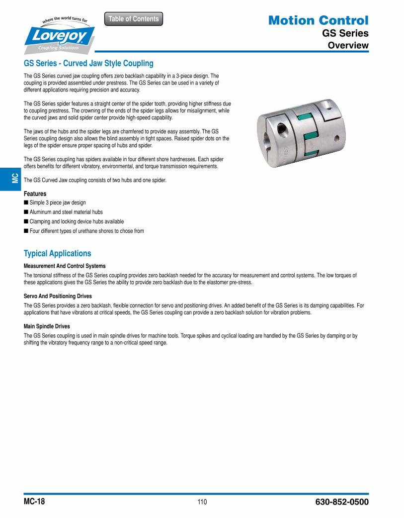
GS Series - Curved Jaw Style CouplingThe GS Series curved jaw coupling offers zero backlash capability in a 3-piece design. The coupling is provided assembled under prestress. The GS Series can be used in a variety of different applications requiring precision and accuracy.
The GS Series spider features a straight center of the spider tooth, providing higher stiffness due to coupling prestress. The crowning of the ends of the spider legs allows for misalignment, while the curved jaws and solid spider center provide high-speed capability.
The jaws of the hubs and the spider legs are chamfered to provide easy assembly. The GS Series coupling design also allows the blind assembly in tight spaces. Raised spider dots on the legs of the spider ensure proper spacing of hubs and spider.
The GS Series coupling has spiders available in four different shore hardnesses. Each spider offers benefits for different vibratory, environmental, and torque transmission requirements.
The GS Curved Jaw coupling consists of two hubs and one spider.
Features ■ Simple 3 piece jaw design
■ Aluminum and steel material hubs
■ Clamping and locking device hubs available
■ Four different types of urethane shores to chose from
Typical ApplicationsMeasurement And Control Systems
The torsional stiffness of the GS Series coupling provides zero backlash needed for the accuracy for measurement and control systems. The low torques of these applications gives the GS Series the ability to provide zero backlash due to the elastomer pre-stress.
Servo And Positioning Drives
The GS Series provides a zero backlash, flexible connection for servo and positioning drives. An added benefit of the GS Series is its damping capabilities. For applications that have vibrations at critical speeds, the GS Series coupling can provide a zero backlash solution for vibration problems.
Main Spindle Drives
The GS Series coupling is used in main spindle drives for machine tools. Torque spikes and cyclical loading are handled by the GS Series by damping or by shifting the vibratory frequency range to a non-critical speed range.
JWJI
SC
JSF
MC
GH
PG
DD
TSP
UJ
VSD
RSL
DED
JWJIS
CJ
SFM
CG
HP
GD
DT
SPU
JVSD
RSLD
ED
111www.lovejoy-inc.com
Table of Contents
MC-19
Motion ControlGS Series
Performance Data
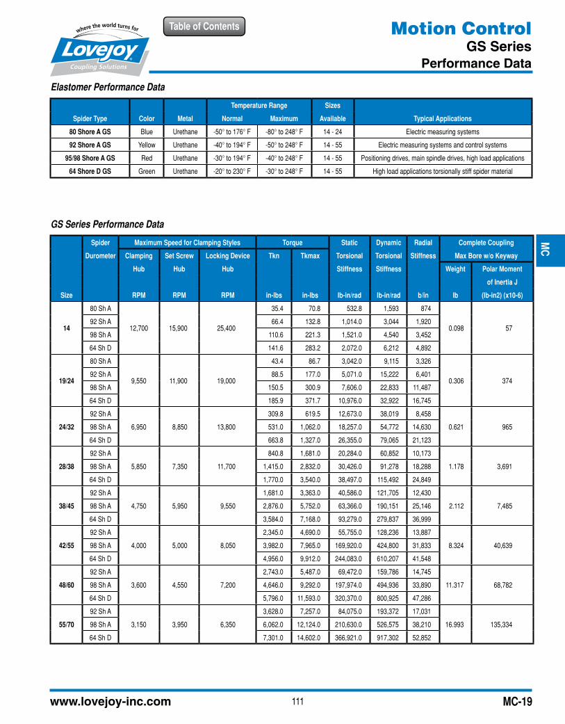
Elastomer Performance Data
Temperature Range Sizes
Spider Type Color Metal Normal Maximum Available Typical Applications
80 Shore A GS Blue Urethane -50° to 176° F -80° to 248° F 14 - 24 Electric measuring systems
92 Shore A GS Yellow Urethane -40° to 194° F -50° to 248° F 14 - 55 Electric measuring systems and control systems
95/98 Shore A GS Red Urethane -30° to 194° F -40° to 248° F 14 - 55 Positioning drives, main spindle drives, high load applications
64 Shore D GS Green Urethane -20° to 230° F -30° to 248° F 14 - 55 High load applications torsionally stiff spider material
GS Series Performance Data
Spider Maximum Speed for Clamping Styles Torque Static Dynamic Radial Complete Coupling
Durometer Clamping Set Screw Locking Device Tkn Tkmax Torsional Torsional Stiffness Max Bore w/o Keyway
Hub Hub Hub Stiffness Stiffness Weight Polar Moment
of Inertia J
Size RPM RPM RPM in-lbs in-lbs lb-in/rad lb-in/rad b/in lb (lb-in2) (x10-6)
14
80 Sh A
12,700 15,900 25,400
35.4 70.8 532.8 1,593 874
0.098 5792 Sh A 66.4 132.8 1,014.0 3,044 1,920
98 Sh A 110.6 221.3 1,521.0 4,540 3,452
64 Sh D 141.6 283.2 2,072.0 6,212 4,892
19/24
80 Sh A
9,550 11,900 19,000
43.4 86.7 3,042.0 9,115 3,326
0.306 37492 Sh A 88.5 177.0 5,071.0 15,222 6,401
98 Sh A 150.5 300.9 7,606.0 22,833 11,487
64 Sh D 185.9 371.7 10,976.0 32,922 16,745
24/32
92 Sh A
6,950 8,850 13,800
309.8 619.5 12,673.0 38,019 8,458
0.621 96598 Sh A 531.0 1,062.0 18,257.0 54,772 14,630
64 Sh D 663.8 1,327.0 26,355.0 79,065 21,123
28/38
92 Sh A
5,850 7,350 11,700
840.8 1,681.0 20,284.0 60,852 10,173
1.178 3,69198 Sh A 1,415.0 2,832.0 30,426.0 91,278 18,288
64 Sh D 1,770.0 3,540.0 38,497.0 115,492 24,849
38/45
92 Sh A
4,750 5,950 9,550
1,681.0 3,363.0 40,586.0 121,705 12,430
2.112 7,48598 Sh A 2,876.0 5,752.0 63,366.0 190,151 25,146
64 Sh D 3,584.0 7,168.0 93,279.0 279,837 36,999
42/55
92 Sh A
4,000 5,000 8,050
2,345.0 4,690.0 55,755.0 128,236 13,887
8.324 40,63998 Sh A 3,982.0 7,965.0 169,920.0 424,800 31,833
64 Sh D 4,956.0 9,912.0 244,083.0 610,207 41,548
48/60
92 Sh A
3,600 4,550 7,200
2,743.0 5,487.0 69,472.0 159,786 14,745
11.317 68,78298 Sh A 4,646.0 9,292.0 197,974.0 494,936 33,890
64 Sh D 5,796.0 11,593.0 320,370.0 800,925 47,286
55/70
92 Sh A
3,150 3,950 6,350
3,628.0 7,257.0 84,075.0 193,372 17,031
16.993 135,33498 Sh A 6,062.0 12,124.0 210,630.0 526,575 38,210
64 Sh D 7,301.0 14,602.0 366,921.0 917,302 52,852
JWJI
SC
JSF
MC
GH
PG
DD
TSP
UJ
VSD
RSL
DED
JWJIS
CJ
SFM
CG
HP
GD
DT
SPU
JVSD
RSLD
ED
112 630-852-0500
Table of Contents
MC-20
Motion ControlGS Series
Dimensional Data
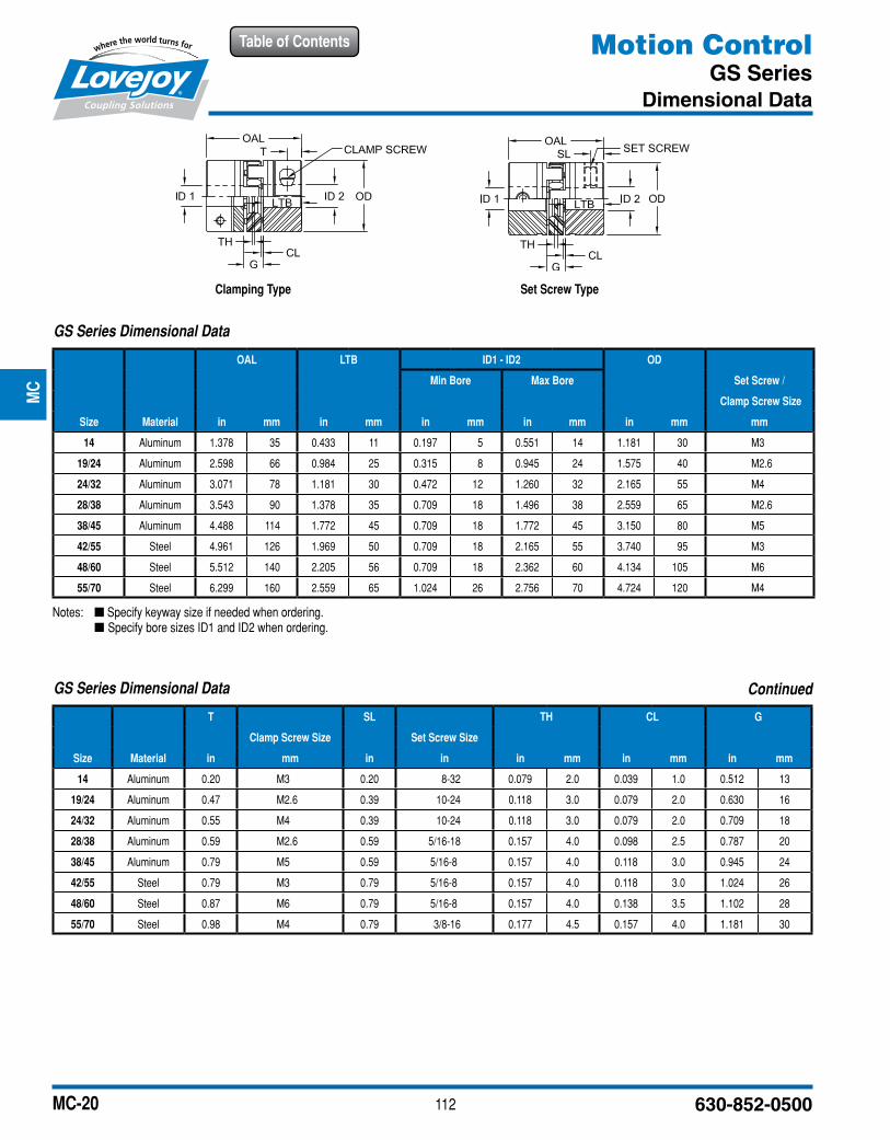
Clamping Type Set Screw Type
Notes: n Specify keyway size if needed when ordering. n Specify bore sizes ID1 and ID2 when ordering.
GS Series Dimensional Data
OAL LTB ID1 - ID2 OD
Min Bore Max Bore Set Screw /
Clamp Screw Size
Size Material in mm in mm in mm in mm in mm mm
14 Aluminum 1.378 35 0.433 11 0.197 5 0.551 14 1.181 30 M3
19/24 Aluminum 2.598 66 0.984 25 0.315 8 0.945 24 1.575 40 M2.6
24/32 Aluminum 3.071 78 1.181 30 0.472 12 1.260 32 2.165 55 M4
28/38 Aluminum 3.543 90 1.378 35 0.709 18 1.496 38 2.559 65 M2.6
38/45 Aluminum 4.488 114 1.772 45 0.709 18 1.772 45 3.150 80 M5
42/55 Steel 4.961 126 1.969 50 0.709 18 2.165 55 3.740 95 M3
48/60 Steel 5.512 140 2.205 56 0.709 18 2.362 60 4.134 105 M6
55/70 Steel 6.299 160 2.559 65 1.024 26 2.756 70 4.724 120 M4
GS Series Dimensional Data
T SL TH CL G
Clamp Screw Size Set Screw Size
Size Material in mm in in in mm in mm in mm
14 Aluminum 0.20 M3 0.20 8-32 0.079 2.0 0.039 1.0 0.512 13
19/24 Aluminum 0.47 M2.6 0.39 10-24 0.118 3.0 0.079 2.0 0.630 16
24/32 Aluminum 0.55 M4 0.39 10-24 0.118 3.0 0.079 2.0 0.709 18
28/38 Aluminum 0.59 M2.6 0.59 5/16-18 0.157 4.0 0.098 2.5 0.787 20
38/45 Aluminum 0.79 M5 0.59 5/16-8 0.157 4.0 0.118 3.0 0.945 24
42/55 Steel 0.79 M3 0.79 5/16-8 0.157 4.0 0.118 3.0 1.024 26
48/60 Steel 0.87 M6 0.79 5/16-8 0.157 4.0 0.138 3.5 1.102 28
55/70 Steel 0.98 M4 0.79 3/8-16 0.177 4.5 0.157 4.0 1.181 30
Continued
JWJI
SC
JSF
MC
GH
PG
DD
TSP
UJ
VSD
RSL
DED
JWJIS
CJ
SFM
CG
HP
GD
DT
SPU
JVSD
RSLD
ED
113www.lovejoy-inc.com
Table of Contents
MC-21
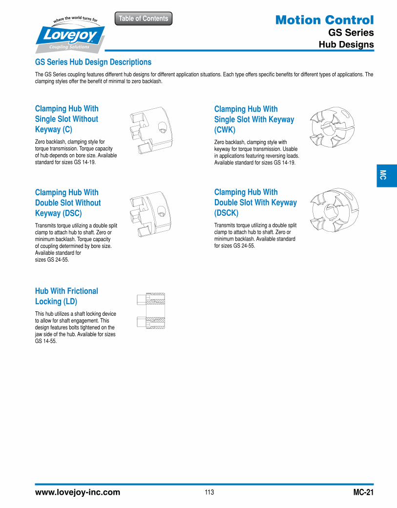
GS Series Hub Design DescriptionsThe GS Series coupling features different hub designs for different application situations. Each type offers specific benefits for different types of applications. The clamping styles offer the benefit of minimal to zero backlash.
Clamping Hub With Single Slot Without Keyway (C)Zero backlash, clamping style for torque transmission. Torque capacity of hub depends on bore size. Available standard for sizes GS 14-19.
Clamping Hub With Single Slot With Keyway (CWK)Zero backlash, clamping style with keyway for torque transmission. Usable in applications featuring reversing loads. Available standard for sizes GS 14-19.
Clamping Hub With Double Slot Without Keyway (DSC)Transmits torque utilizing a double split clamp to attach hub to shaft. Zero or minimum backlash. Torque capacity of coupling determined by bore size. Available standard for sizes GS 24-55.
Clamping Hub With Double Slot With Keyway (DSCK)Transmits torque utilizing a double split clamp to attach hub to shaft. Zero or minimum backlash. Available standard for sizes GS 24-55.
Hub With Frictional Locking (LD)This hub utilizes a shaft locking device to allow for shaft engagement. This design features bolts tightened on the jaw side of the hub. Available for sizes GS 14-55.
Motion ControlGS Series
Hub Designs
JWJI
SC
JSF
MC
GH
PG
DD
TSP
UJ
VSD
RSL
DED
JWJIS
CJ
SFM
CG
HP
GD
DT
SPU
JVSD
RSLD
ED
114 630-852-0500
Table of ContentsJW
JIS
CJ
SFM
CG
HP
GD
DT
SPU
JVS
DR
SLD
ED
JWJIS
CJ
SFM
CG
HP
GD
DT
SPU
JVSD
RSLD
ED
MC-22
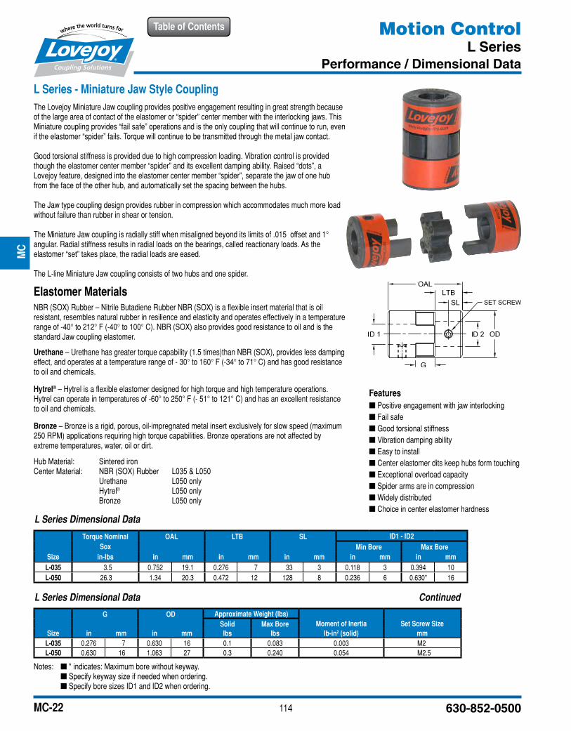
L Series - Miniature Jaw Style CouplingThe Lovejoy Miniature Jaw coupling provides positive engagement resulting in great strength because of the large area of contact of the elastomer or “spider” center member with the interlocking jaws. This Miniature coupling provides “fail safe” operations and is the only coupling that will continue to run, even if the elastomer “spider” fails. Torque will continue to be transmitted through the metal jaw contact.
Good torsional stiffness is provided due to high compression loading. Vibration control is provided though the elastomer center member “spider” and its excellent damping ability. Raised “dots”, a Lovejoy feature, designed into the elastomer center member “spider”, separate the jaw of one hub from the face of the other hub, and automatically set the spacing between the hubs.
The Jaw type coupling design provides rubber in compression which accommodates much more load without failure than rubber in shear or tension.
The Miniature Jaw coupling is radially stiff when misaligned beyond its limits of .015 offset and 1° angular. Radial stiffness results in radial loads on the bearings, called reactionary loads. As the elastomer “set” takes place, the radial loads are eased.
The L-line Miniature Jaw coupling consists of two hubs and one spider.
Elastomer MaterialsNBR (SOX) Rubber – Nitrile Butadiene Rubber NBR (SOX) is a flexible insert material that is oil resistant, resembles natural rubber in resilience and elasticity and operates effectively in a temperature range of -40° to 212° F (-40° to 100° C). NBR (SOX) also provides good resistance to oil and is the standard Jaw coupling elastomer.
Urethane – Urethane has greater torque capability (1.5 times)than NBR (SOX), provides less damping effect, and operates at a temperature range of - 30° to 160° F (-34° to 71° C) and has good resistance to oil and chemicals.
Hytrel® – Hytrel is a flexible elastomer designed for high torque and high temperature operations. Hytrel can operate in temperatures of -60° to 250° F (- 51° to 121° C) and has an excellent resistance to oil and chemicals.
Bronze – Bronze is a rigid, porous, oil-impregnated metal insert exclusively for slow speed (maximum 250 RPM) applications requiring high torque capabilities. Bronze operations are not affected by extreme temperatures, water, oil or dirt.
Hub Material: Sintered ironCenter Material: NBR (SOX) Rubber L035 & L050 Urethane L050 only Hytrel® L050 only Bronze L050 only
Features ■ Positive engagement with jaw interlocking ■ Fail safe ■ Good torsional stiffness ■ Vibration damping ability ■ Easy to install ■ Center elastomer dits keep hubs form touching ■ Exceptional overload capacity ■ Spider arms are in compression ■ Widely distributed ■ Choice in center elastomer hardness
L Series Dimensional Data
Torque Nominal OAL LTB SL ID1 - ID2Sox Min Bore Max Bore
Size in-lbs in mm in mm in mm in mm in mmL-035 3.5 0.752 19.1 0.276 7 33 3 0.118 3 0.394 10L-050 26.3 1.34 20.3 0.472 12 128 8 0.236 6 0.630* 16
L Series Dimensional Data Continued
G OD Approximate Weight (lbs)Solid Max Bore Moment of Inertia Set Screw Size
Size in mm in mm lbs lbs lb-in2 (solid) mmL-035 0.276 7 0.630 16 0.1 0.083 0.003 M2L-050 0.630 16 1.063 27 0.3 0.240 0.054 M2.5
Motion ControlL Series
Performance / Dimensional Data
Notes: n * indicates: Maximum bore without keyway. n Specify keyway size if needed when ordering. n Specify bore sizes ID1 and ID2 when ordering.