johanson technology multi-layer high-q capacitors · high q performance, and exhibit np0...
TRANSCRIPT

7www.johansontechnology.com
These lines of multilayer capacitors have been developed for High-Q and microwave applications.
• The S-Series (R07S, R14S, R15S) capacitors give an ultra-high Q performance, and exhibit NP0 temperature characteris-tics.
• The L-Series (R05L) capacitors give mid-high Q performance, and exhibit NP0 temperature characteristics.
• The E-Series (S42E, S48E, S58E) capacitors give excellent high-Q performance from HF to Microwave frequencies. Typical uses are high voltage, high current applications. They are offered in chip (Ni barrier or Non-Magnetic Pt.-Ag) or in Non-Magnetic leaded form.
• RoHS compliance is standard for all unleaded parts (see termination options box).
• Automotive versions (AEC-Q200) of R05L, R07S, R14S, R15S, and S42E series are available on request
MULTI-LAYER HIGH-Q CAPACITORS
HOW TO ORDER
Part Number written: 252S48E470KV4E
WVDC2
250 = 25 V500 = 50V201 = 200 V 251 = 250 V 501 = 500 V102 = 1000 V152 = 1500 V252 = 2500 V362 = 3600 V 722 = 7200 V
252
CASE SIZER05 (0201)R07 (0402)R14 (0603)R15 (0805)S42 (1111) S48 (2525) S58 (3838)
S48 470
TOLERANCE< 10pF
A = ± 0.05 pF B = ± 0.10 pF C = ± 0.25 pF D = ± 0.50 pF
≥ 10pFF = ±1 %G = ±2%J = ±5%K = ± 10%
For tolerance availability, see chart.
K
MARKING3 = Cap Code & Tolerance4 = No Marking6 = EIA Code
(Marking option is only available
on 0805 and larger case sizes)
4
TERMINATIONNickel Barrier V = Ni/Sn (Green) T = Ni/SnPb G = Ni/Au (Green)
Non-Mag1 U = Cu/Sn (Green) C = Cu/SnPb
Leaded (All Non-
Mag)1 1 = Microstrip2 = Axial Ribbon 3 = Axial Wire4 = Radial Ribbon5 = Radial Wire
V
CAPACITANCE (pF)1st two digits aresignificant; third digitdenotes number ofzeros, R = decimal.
100 = 10 pF101 = 100 pF
PACKAGING S = Bulk
W = Waffle Pack 0201 - 0603 Y = Paper 5” Reel T = Paper 7” Reel R1 = Paper 13” Reel J1 = Paper 5” Reel - Horizontally Oriented Electrodes
N1 = Paper 5” Reel - Vertically Oriented Electrodes
L1 = Paper 7” Reel - Horizontally Oriented Electrodes
V1 = Paper 7” Reel - Vertically Oriented Electrodes
0805 - 3838Z = Embossed 5” ReelE = Embossed 7” ReelU1 = Embossed 13” ReelM1 = Embossed 5” Reel - Horizontally Oriented Electrodes
Q1 = Embossed 5” Reel - Vertically Oriented Electrodes
G1 = Embossed 7” Reel - Horizontally Oriented Electrodes
P1 = Embossed 7” Reel - Vertically Oriented Electrodes
Tape specificationsconform to EIA RS481
E
DIELECTRICS = Ultra High Q NPOL = High Q NPOE = Ultra High Q NPO, High Voltage, High PowerG = Fully Oriented, Ultra High-Q NPO
E
1 - Not available for all MLCC - Call factory for info. 2 - WVDC - Working Voltage DC.3 -Qualification required for automotive application, Not available for all series - Call factory for info.
QUALIFICATION AEC-Q200qualification 3
(optional)
-AEC

8 www.johansontechnology.com
RF Power Applications
0201 (R05) 0402(R07S)
0603(R14S)
0805(R15S)
0805(R15L)
1111(S42E)
2525(S48E)
3838(S58E)NPO
(R05L)NPO
(R05G)CapacitancepF Code0.1 0R1
A
B
C
D
0.2 0R2 25/50 V 25 V 50/250 V 250 V 500V 1500V0.3 0R3 25/50 V 25 V 50/250 V 250 V 250 V 500V 1500V0.4 0R4 25/50 V 25 V 50/250 V 250 V 250 V 500V 1500V0.5 0R5 25/50 V 25 V 50/250 V 250 V 250 V 500V 1500V 3600V0.6 0R6 25/50 V 25 V 50/250 V 250 V 250 V 500V 1500V 3600V 3600V 7200V0.7 0R7 25/50 V 25 V 50/250 V 250 V 250 V 500V 1500V 3600V 3600V 7200V0.8 0R8 25/50 V 25 V 50/250 V 250 V 250 V 500V 1500V 3600V 3600V 7200V0.9 0R9 25/50 V 25 V 50/250 V 250 V 250 V 500V 1500V 3600V 3600V 7200V1.0 1R0 25/50 V 25 V 50/250 V 250 V 250 V 500V 1500V 3600V 3600V 7200V1.1 1R1 25/50 V 25 V 50/250 V 250 V 250 V 500V 1500V 3600V 3600V 7200V1.2 1R2 25/50 V 25 V 50/250 V 250 V 250 V 500V 1500V 3600V 3600V 7200V1.3 1R3 25/50 V 25 V 50/250 V 250 V 250 V 500V 1500V 3600V 3600V 7200V1.4 1R4 25/50 V 25 V 50/250 V 250 V 250 V 500V 1500V 3600V 3600V 7200V1.5 1R5 25/50 V 25 V 50/250 V 250 V 250 V 500V 1500V 3600V 3600V 7200V1.6 1R6 25/50 V 25 V 50/250 V 250 V 250 V 500V 1500V 3600V 3600V 7200V1.7 1R7 25/50 V 25 V 50/250 V 250 V 250 V 500V 1500V 3600V 3600V 7200V1.8 1R8 25/50 V 25 V 50/250 V 250 V 250 V 500V 1500V 3600V 3600V 7200V1.9 1R9 25/50 V 25 V 50/250 V 250 V 250 V 500V 1500V 3600V 3600V 7200V2.0 2R0 25/50 V 25 V 50/250 V 250 V 250 V 500V 1500V 3600V 3600V 7200V2.1 2R1 25/50 V 25 V 50/250 V 250 V 250 V 500V 1500V 3600V 3600V 7200V2.2 2R2 25/50 V 25 V 50/250 V 250 V 250 V 500V 1500V 3600V 3600V 7200V2.4 2R4 25/50 V 25 V 50/250 V 250 V 250 V 500V 1500V 3600V 3600V 7200V2.7 2R7 25/50 V 25 V 50/250 V 250 V 250 V 500V 1500V 3600V 3600V 7200V3.0 3R0 25/50 V 25 V 50/250 V 250 V 250 V 500V 1500V 3600V 3600V 7200V3.3 3R3 25/50 V 25 V 50/250 V 250 V 250 V 500V 1500V 3600V 3600V 7200V3.6 3R6 25/50 V 25 V 50/200 V 250 V 250 V 500V 1500V 3600V 3600V 7200V3.9 3R9 25/50 V 25 V 50/200 V 250 V 250 V 500V 1500V 3600V 3600V 7200V4.3 4R3 25/50 V 25 V 50/200 V 250 V 250 V 500V 1500V 3600V 3600V 7200V4.7 4R7 25/50 V 25 V 50/200 V 250 V 250 V 500V 1500V 3600V 3600V 7200V5.1 5R1
A** BCD
25/50 V 25 V 50/200 V 250 V 250 V 500V 1500V 3600V 3600V 7200V5.6 5R6 25/50 V 25 V 50/200 V 250 V 250 V 500V 1500V 3600V 3600V 7200V6.2 6R2 25/50 V 25 V 50/200 V 250 V 250 V 500V 1500V 3600V 3600V 7200V6.8 6R8 25/50 V 25 V 50/200 V 250 V 250 V 500V 1500V 3600V 3600V 7200V7.5 7R5 25/50 V 25 V 50/200 V 250 V 250 V 500V 1500V 3600V 3600V 7200V8.2 8R2 25/50 V 25 V 50/200 V 250 V 250 V 500V 1500V 3600V 3600V 7200V9.1 9R1 25/50 V 25 V 50/200 V 250 V 250 V 500V 1500V 3600V 3600V 7200V10 100
F
G
J
K
25/50 V 25 V 50/200 V 250 V 250 V 500V 1500V 3600V 3600V 7200V11 110 25/50 V 25 V 50/200 V 250 V 250 V 500V 1500V 3600V 3600V 7200V12 120 25/50 V 25 V 50/200 V 250 V 250 V 500V 1500V 3600V 3600V 7200V13 130 25/50 V 25 V 50/200 V 250 V 250 V 500V 1500V 3600V 3600V 7200V15 150 25/50 V 25 V 50/200 V 250 V 250 V 500V 1500V 3600V 3600V 7200V16 160 25/50 V 25 V 50/200 V 250 V 250 V 500V 1500V 3600V 3600V 7200V18 180 25/50 V 25 V 50/200 V 250 V 250 V 500V 1500V 3600V 3600V 7200V20 200 25/50 V 50/200 V 250 V 250 V 500V 1500V 3600V 3600V 7200V22 220 25/50 V 50/200 V 250 V 250 V 500V 1500V 3600V 3600V 7200V24 240 25/50 V 50/200 V 250 V 250 V 500V 1500V 3600V 3600V 7200V27 270 25/50 V 50/200 V 250 V 250 V 500V 1500V 3600V 3600V 7200V30 300 25/50 V 50/200 V 250 V 250 V 500V 1500V 3600V 3600V 7200V33 330 25/50 V 50/200 V 250 V 250 V 500V 1500V 3600V 3600V 7200V
LOW ESR / HIGH-Q CAPACITOR SELECTION CHART
EIA Size
Cap. Value
Consult factory for Non-Standard values.**A tolerance only available for R07S (0402) and R14S(0603) caps

9www.johansontechnology.com
RF Power Applications
0201 (R05) 0402(R07S)
0603(R14S)
0805(R15S)
0805(R15L)
1111(S42E)
2525(S48E)
3838(S58E)NPO
(R05L)NP0
(R05G)Capacitance Toler-
ancepF Code36 360
F
G
J
K
25/50 V 250 V 250 V 500V 1500V 3600V 3600V 7200V39 390 25/50 V 250 V 250 V 500V 1500V 3600V 3600V 7200V43 430 25/50 V 250 V 250 V 500V 1500V 3600V 3600V 7200V47 470 25/50 V 250 V 250 V 500V 1500V 3600V 3600V 7200V51 510 25/50 V 250 V 250 V 500V 1500V 3600V 3600V 7200V56 560 25/50 V 250 V 250 V 500V 1500V 3600V 3600V 7200V62 620 25/50 V 250 V 250 V 500V 1500V 3600V 3600V 7200V68 680 25/50 V 250 V 250 V 500V 1500V 3600V 3600V 7200V75 750 25/50 V 250 V 250 V 500V 1500V 3600V 3600V 7200V82 820 25/50 V 250 V 250 V 500V 1500V 3600V 3600V 7200V91 910 25/50 V 250 V 250 V 500V 1500V 3600V 3600V 7200V100 101 25/50 V 250 V 250 V 500V 1500V 3600V 3600V 7200V110 111 250 V 300V 1500V 2500V 3600V 7200V120 121 250 V 300V 1000V 2500V 3600V 7200V130 131 250 V 300V 1000V 2500V 3600V 7200V150 151 250 V 300V 1000V 2500V 3600V 7200V160 161 250 V 300V 1000V 2500V 3600V 7200V180 181 250 V 300V 1000V 2500V 3600V 7200V200 201 250 V 300V 1000V 2500V 3600V220 221 250 V 200V 1000V 2500V 3600V240 241 500V 200V 600V 2500V 3600V270 271 500V 200V 600V 2500V 3600V300 301 500V 200V 600V 1500V 3600V330 331 500V 200V 600V 1500V 3600V360 361 500V 200V 600V 1500V 3600V390 391 500V 200V 500V 1500V 3600V430 431
G
J
K
500V 200V 500V 1500V 2500V470 471 500V 200V 500V 1500V 2500V510 511 100V 200V 500V 1000V 2500V560 561 100V 200V 500V 1000V 2500V620 621 100V 200V 500V 1000V 2500V680 681 50V 200V 1000V 2500V750 751 50V 200V 1000V 2500V820 821 50V 200V 1000V 2500V910 911 50V 200V 1000V 1000V1000 102 50V 200V 1000V 1000V1200 122 50V 1000V 1000V1500 152 50V 500V 1000V1800 182 50V 500V 1000V2200 222 50V 300V 1000V2700 272 300V 500V3300 332 500V3900 392 500V4700 472 500V5100 512 500V
10000 103
LOW ESR / HIGH-Q CAPACITOR SELECTION CHART
EIA Size
Cap. Value
Consult factory for Non-Standard values.
10 www.johansontechnology.comwww.johansontechnology.com
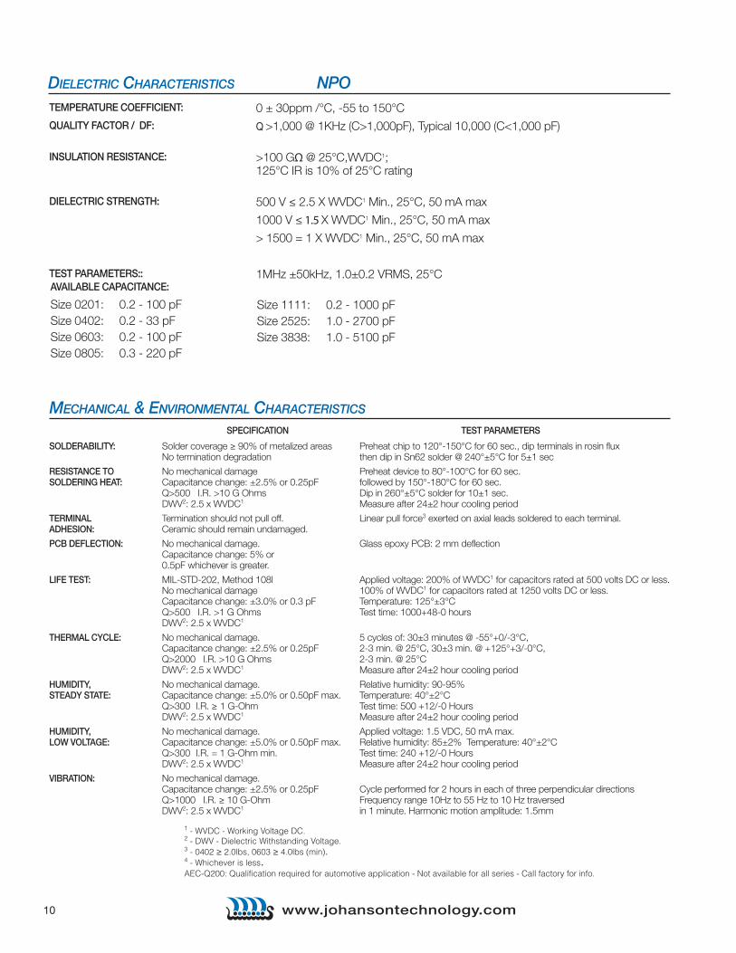
MECHANICAL & ENVIRONMENTAL CHARACTERISTICS
SPECIFICATION TEST PARAMETERS SOLDERABILITY: Solder coverage ≥ 90% of metalized areas Preheat chip to 120°-150°C for 60 sec., dip terminals in rosin flux No termination degradation then dip in Sn62 solder @ 240°±5°C for 5±1 sec
RESISTANCE TO No mechanical damage Preheat device to 80°-100°C for 60 sec. SOLDERING HEAT: Capacitance change: ±2.5% or 0.25pF followed by 150°-180°C for 60 sec. Q>500 I.R. >10 G Ohms Dip in 260°±5°C solder for 10±1 sec. DWV2: 2.5 x WVDC1 Measure after 24±2 hour cooling period
TERMINAL Termination should not pull off. Linear pull force3 exerted on axial leads soldered to each terminal. ADHESION: Ceramic should remain undamaged.
PCB DEFLECTION: No mechanical damage. Glass epoxy PCB: 2 mm deflection Capacitance change: 5% or 0.5pF whichever is greater.
LIFE TEST: MIL-STD-202, Method 108l Applied voltage: 200% of WVDC1 for capacitors rated at 500 volts DC or less. No mechanical damage 100% of WVDC1 for capacitors rated at 1250 volts DC or less. Capacitance change: ±3.0% or 0.3 pF Temperature: 125°±3°C Q>500 I.R. >1 G Ohms Test time: 1000+48-0 hours DWV2: 2.5 x WVDC1
THERMAL CYCLE: No mechanical damage. 5 cycles of: 30±3 minutes @ -55°+0/-3°C, Capacitance change: ±2.5% or 0.25pF 2-3 min. @ 25°C, 30±3 min. @ +125°+3/-0°C, Q>2000 I.R. >10 G Ohms 2-3 min. @ 25°C DWV2: 2.5 x WVDC1 Measure after 24±2 hour cooling period
HUMIDITY, No mechanical damage. Relative humidity: 90-95% STEADY STATE: Capacitance change: ±5.0% or 0.50pF max. Temperature: 40°±2°C Q>300 I.R. ≥ 1 G-Ohm Test time: 500 +12/-0 Hours DWV2: 2.5 x WVDC1 Measure after 24±2 hour cooling period
HUMIDITY, No mechanical damage. Applied voltage: 1.5 VDC, 50 mA max. LOW VOLTAGE: Capacitance change: ±5.0% or 0.50pF max. Relative humidity: 85±2% Temperature: 40°±2°C Q>300 I.R. = 1 G-Ohm min. Test time: 240 +12/-0 Hours DWV2: 2.5 x WVDC1 Measure after 24±2 hour cooling period
VIBRATION: No mechanical damage. Capacitance change: ±2.5% or 0.25pF Cycle performed for 2 hours in each of three perpendicular directions Q>1000 I.R. ≥ 10 G-Ohm Frequency range 10Hz to 55 Hz to 10 Hz traversed DWV2: 2.5 x WVDC1 in 1 minute. Harmonic motion amplitude: 1.5mm
DIELECTRIC CHARACTERISTICS NPO 0 ± 30ppm /°C, -55 to 150°C
Q >1,000 @ 1KHz (C>1,000pF), Typical 10,000 (C<1,000 pF)
>100 GΩ @ 25°C,WVDC1; 125°C IR is 10% of 25°C rating
500 V ≤ 2.5 X WVDC1 Min., 25°C, 50 mA max
1000 V ≤ 1.5 X WVDC1 Min., 25°C, 50 mA max
> 1500 = 1 X WVDC1 Min., 25°C, 50 mA max
1MHz ±50kHz, 1.0±0.2 VRMS, 25°C
TEMPERATURE COEFFICIENT:
QUALITY FACTOR / DF:
INSULATION RESISTANCE:
DIELECTRIC STRENGTH:
TEST PARAMETERS::
Size 1111: 0.2 - 1000 pFSize 2525: 1.0 - 2700 pFSize 3838: 1.0 - 5100 pF
AVAILABLE CAPACITANCE:
Size 0201: 0.2 - 100 pFSize 0402: 0.2 - 33 pFSize 0603: 0.2 - 100 pFSize 0805: 0.3 - 220 pF
1 - WVDC - Working Voltage DC. 2 - DWV - Dielectric Withstanding Voltage. 3 - 0402 ≥ 2.0lbs, 0603 ≥ 4.0lbs (min). 4 - Whichever is less.AEC-Q200: Qualification required for automotive application - Not available for all series - Call factory for info.

11www.johansontechnology.com
BENIFITS OF USING ORIENTED CAPACITORS
www.johansontechnology.com
Size Units Length Width Thickness End Band
EIA 0201 In .024 ±.001 .012 ±.001 .012 ±.001 .008 Max.
Metric (0603) mm (0.60 ±0.03) (0.30 ±0.03) (0.30 ±0.03) (0.20 Max.)
EIA 0402 In .040 ±.004 .020 ±.004 .020 ±.004 .010 ±.006
Metric (1005) mm (1.02 ±0.1) (0.51 ±0.1) (0.51 ±0.1) (0.25 ±.15)
EIA 0603 In .062 ±.006 .032 ±.006 .030 +.005/-.003 .014 ±.006
Metric (1608) mm (1.57 ±0.15) (0.81 ±0.15) (0.76 +.13-.08) (0.35 ±.15)
EIA 0805 In .080 ±.008 .050 ±.008 .040 ±.006 .020 ±.010
Metric (2012) mm (2.03 ±0.20) (1.27 ±0.20) (1.02 ±.15) (0.50 ±.25)
MECHANICAL CHARACTERISTICS
Horizontal Electrode Orientation Vertical Electrode Orientation
HORIZONTAL AND VERTICLE ORIENTED CAPACITORS
APPLICATIONS & FEATURES
Size: EIA 0201, 0805, 1111Performance: SRF’s up to 20 GHz, Ultra High Q, Tight tolerance, Ultralow ESRTermination: Ni/Au, Ni/Sn, Ni/SnPbApplications: High Frequency Wireless Communications, Portable Wireless Products, Battery Powered
Products
• Consistent Orientation - Improved repeatability of production circuits.• Consistent Orientation - More consistent filter performance.• Vertical Orientation - The elimination of parallel frequencies.• Vertical Orinetation - Lower inductance for a given capacitor.• Horizontal Orientation - Lower coupling between adjacent capacitors.
RoHS Compliant

12 www.johansontechnology.com
Unleaded Termination Codes “V” (Ni/Sn), “T” (Ni/SnPb), “U” (Cu/Sn non-mag), “C”
(Cu/SnPb non-mag)
Microstrip Ribbon Leads (Non-Magnetic), Termination Code “1”
Axial Ribbon Leads (Non-Magnetic), Termi-nation Code “2”
Axial Wire Leads (Non-Magnetic), Termination Code “3”
Radial Ribbon Leads (Non-Magnetic), Ter-mination Code “4”
Radial Wire Leads (Non-Magnetic), Termination Code “5”
Termination Size Units L Tol W Tol T E / B Tol
V,TU,C
S42E In 0.110 +.020 -.010 0.110 +/- .015 0.102 Max. 0.015 Typ. +/- 0.008
mm 2.79 +0.51 -0.25 2.79 +/- 0.38 2.59 Max. 0.38 Typ. +/- 0.20
S48E In 0.230 +.025 -.010 0.250 +/- .015 0.150 Max. 0.025 Typ.
mm 5.84 +0.63 -0.25 6.35 +/- 0.38 3.81 Max. 0.63 Typ.
S58E In 0.380 +.015 -.010 0.380 +/- .010 0.170 Max. 0.025 Typ.
mm 9.65 +0.38 -0.25 9.65 +/- 0.25 4.32 Max. 0.63 Typ.
For all E-Series Models:
OPERATING TEMP. : -55 to +125°C INSULATION RESISTANCE: >10G Ω @ 25°C TEMPERATURE COEFFICIENT: 0 ± 30ppm /°C, -55 to 125°C
DISSIPATION FACTOR (TYP.): < 0.05% @ 1 MHz
E-SERIES TERMINATIONS AND LEADS
L
E/B
T
W
e
LL LL
X
e
LL LL
X
LL
W
X
XX
LL
e eLL
X
e e
LLLL
LLLL
W
T
W
T
Lead Size LL(min) X Tol e e-Tol
1
S42E0.25 0.093 +/-0.005 0.004 +/- 0.002
6.40 2.36 +/- 0.13 0.102 +/- 0.051
S48E0.394 0.217 +/- 0.02 0.009 - 0.0019/+ 0.0031
10.0 5.5 +/- 0.50 0.220 - 0.050/+ 0.080
S58E0.748 0.35 +/- 0.02 0.010 - 0.0019/+ 0.0039
19.00 8.90 +/- 0.50 0.250 - 0.050/+ 0.100
2
S42E0.25 0.093 +/-0.005 0.004 +/- 0.002
6.40 2.36 +/- 0.13 0.102 +/- 0.051
S48E0.394 0.217 +/- 0.02 0.009 - 0.0019/+ 0.0031
10.00 5.50 +/- 0.50 0.220 - 0.050/+ 0.080
S58E0.748 0.35 +/- 0.02 0.010 - 0.0019/+ 0.0039
19.00 8.90 +/- 0.50 0.25 - 0.050/+ 0.100
3
S42E0.25
0.020in (0.511) diameter wire
6.40
S48E0.394
10.00
S58E0.748
19.00
CHIP DIMENSIONS
Drawings not to scale
Lead Size LL(min) X Tol e e-Tol
4
S42E0.352 0.093 +/-0.005 0.004 +/- 0.002
8.90 2.36 +/- 0.13 0.102 +/- 0.051
S48E0.501 0.217 +/- 0.02 0.009 - 0.0019/+ 0.0031
12.70 5.50 +/- 0.50 0.220 - 0.050/+ 0.080
S58E0.886 0.35 +/- 0.02 0.010 - 0.0019/+ 0.0039
22.50 8.90 +/- 0.50 0.25 - 0.050/+ 0.100
5
S42E0.25
0.020in (0.511) diameter wire
6.40
S48E0.394
10.00
S58E0.748
19.00

13www.johansontechnology.com
RF CHARACTERISTICS - 0402 R07S SERIES More data at: https://jtisoft.johansontechnology.com
RF CHARACTERISTICS - 0201 R05L SERIES More data at: https://jtisoft.johansontechnology.com
Resonant Frequency : 0201/R05L
1
10
100
1 10 100
Reso
nant
freq
uenc
y (G
Hz)
Capacitance value (pF)
SRF
0201 R05L Resonant frequency
Typical values of SRF with: Series mounting Horizontal orientation 14 mil-thick FR4 substrate
0
50
100
150
200
250
300
0 500 1000 1500 2000
ESR
(mΩ)
Freq (MHz)
3.0 pF
10 pF
33 pF
56 pF
100 pF
0201 R05L Equivalent Series Resistance (ESR)
Typical values
1
10
100
1000
10000
0 500 1000 1500 2000
Q fa
ctor
Freq (MHz)
3.0 pF
10 pF
33 pF
56 pF
100 pF
0201 R05L Q factor
0
0.5
1
1.5
2
2.5
3
0 500 1000 1500 2000
Max
imum
cur
rent
(A rm
s)
Freq (MHz)
3 pF
10 pF
33 pF
56 pF
100 pF
Estimated maximum current based on Ambient temperature = 65 °C Thermal resistance of DUT on
substrate = 300°C/W Infinite heatsink Duty cycle=100%
0201 R05L Max Current
1
10
0.1 1 10
Reso
nant
freq
uenc
y (G
Hz)
Capacitance value (pF)
SRF
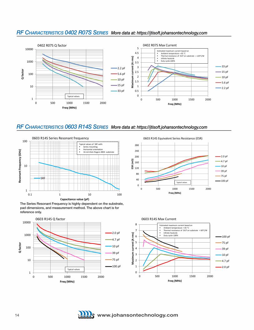
Typical values of SRF with: Series mounting Horizontal orientation 16 mil-thick Rogers 4003 substrate
0402 R07S Series Resonant frequency
0
50
100
150
200
250
0 500 1000 1500 2000
ESR
(mΩ)
Freq (MHz)
2.2 pF
5.6 pF
10 pF
15 pF
33 pF
Typical values
0402 R07S Equivalent Series Resistance (ESR)
The Series Resonant Frequency is highly dependent on the substrate, pad dimensions, and measurement method. The above chart is for reference only.
The Series Resonant Frequency is highly dependent on the substrate, pad dimensions, and measurement method. The above chart is for reference only.
14 www.johansontechnology.com
RF CHARACTERISTICS 0402 R07S SERIES More data at: https://jtisoft.johansontechnology.com
RF CHARACTERISTICS 0603 R14S SERIES More data at: https://jtisoft.johansontechnology.com
1
10
100
1000
10000
0 500 1000 1500 2000
Q fa
ctor
Freq (MHz)
2.2 pF
5.6 pF
10 pF
15 pF
33 pF
Typical values
0402 R07S Q factor
0603 R14S Series Resonant frequency
1
10
100
0.1 1 10 100
Reso
nant
freq
uenc
y (G
Hz)
Capacitance value (pF)
SRF
Typical values of SRF with: Series mounting Horizontal orientation 16 mil-thick Rogers 4003 substrate
0603 R14S Equivalent Series Resistance (ESR)
Typical values
0
40
80
120
160
200
240
280
0 500 1000 1500 2000
ESR
(mΩ)
Freq (MHz)
2.0 pF
4.7 pF
10 pF
39 pF
75 pF
100 pF
0603 R14S Q factor
1
10
100
1000
10000
0 500 1000 1500 2000
Q fa
ctor
Freq (MHz)
2.0 pF
4.7 pF
10 pF
39 pF
75 pF
100 pFTypical values
0603 R14S Max Current
0
1
2
3
4
5
6
7
8
0 500 1000 1500 2000
Max
imum
cur
rent
(A rm
s)
Freq (MHz)
100 pF
75 pF
39 pF
10 pF
4.7 pF
2.0 pF
Estimated maximum current based on Ambient temperature = 65 °C Thermal resistance of DUT on substrate = 60°C/W Infinite heatsink Duty cycle=100%
0402 R07S Max Current
0
0.5
1
1.5
2
2.5
3
3.5
4
4.5
5
0 500 1000 1500 2000
Max
imum
cur
rent
(A rm
s)
Freq (MHz)
33 pF
15 pF
10 pF
5.6 pF
2.2 pF
Estimated maximum current based on Ambient temperature = 65 °C Thermal resistance of DUT on substrate = 120°C/W Infinite heatsink Duty cycle=100%
The Series Resonant Frequency is highly dependent on the substrate, pad dimensions, and measurement method. The above chart is for reference only.
15www.johansontechnology.com
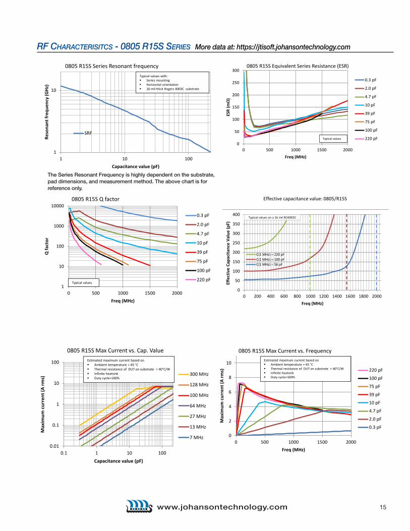
RF CHARACTERISITCS - 0805 R15S SERIES More data at: https://jtisoft.johansontechnology.com
Effective capacitance value: 0805/R15S
0
50
100
150
200
250
300
350
400
0 200 400 600 800 1000 1200 1400 1600 1800 2000
Effe
ctiv
e Ca
paci
tanc
e Va
lue
(pF)
Freq (MHz)
C(1 MHz) = 220 pFC(1 MHz) = 100 pFC(1 MHz) = 56 pF
Typical values on a 16 mil RO4003C
0805 R15S Series Resonant frequency
1
10
1 10 100
Reso
nant
freq
uenc
y (G
Hz)
Capacitance value (pF)
SRF
Typical values with: Series mounting Horizontal orientation 16 mil-thick Rogers 4003C substrate
0805 R15S Equivalent Series Resistance (ESR)
0
50
100
150
200
250
300
0 500 1000 1500 2000
ESR
(mΩ)
Freq (MHz)
0.3 pF
2.0 pF
4.7 pF
10 pF
39 pF
75 pF
100 pF
220 pFTypical values
0805 R15S Q factor
1
10
100
1000
10000
0 500 1000 1500 2000
Q fa
ctor
Freq (MHz)
0.3 pF
2.0 pF
4.7 pF
10 pF
39 pF
75 pF
100 pF
220 pFTypical values
0805 R15S Max Current vs. Cap. Value
0.01
0.1
1
10
100
0.1 1 10 100
Max
imum
cur
rent
(A rm
s)
Capacitance value (pF)
300 MHz
128 MHz
100 MHz
64 MHz
27 MHz
13 MHz
7 MHz
Estimated maximum current based on Ambient temperature = 65 °C Thermal resistance of DUT on substrate = 40°C/W Infinite heatsink Duty cycle=100%
0805 R15S Max Current vs. Frequency
0
2
4
6
8
10
0 500 1000 1500 2000
Max
imum
cur
rent
(A rm
s)
Freq (MHz)
220 pF
100 pF
75 pF
39 pF
10 pF
4.7 pF
2.0 pF
0.3 pF
Estimated maximum current based on Ambient temperature = 65 °C Thermal resistance of DUT on substrate = 40°C/W Infinite heatsink Duty cycle=100%
The Series Resonant Frequency is highly dependent on the substrate, pad dimensions, and measurement method. The above chart is for reference only.
16 www.johansontechnology.com
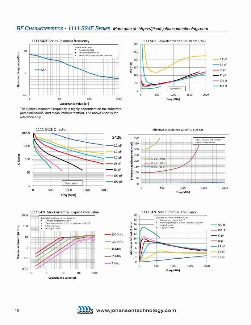
RF CHARACTERISTICS - 1111 S24E SERIES More data at: https://jtisoft.johansontechnology.com
Effective capacitance value: 1111/S42E
0
50
100
150
200
250
300
350
400
0 500 1000 1500 2000
Effe
ctiv
e ca
paci
tanc
e va
lue
(pF)
Freq (MHz)
C(1 MHz) = 300pF
C(1 MHz) = 100 pF
C(1 MHz) = 10 pF
Typical values on a 60-mil thick Rogers 4350B substrate
0.1
1
10
1 10 100 1000
Reso
nant
freq
uenc
y (G
Hz)
Capacitance value (pF)
SRF
Typical values with: Series mounting Horizontal orientation 60 mil-thick Rogers 4350B substrate
1111 S42E Series Resonant frequency
0
50
100
150
200
250
300
0 500 1000 1500 2000
ESR
(mΩ)
Freq (MHz)
1.2 pF
4.7 pF
10 pF
33 pF
100 pF
300 pFTypical values
1111 S42E Equivalent Series Resistance (ESR)
1
10
100
1000
10000
0 500 1000 1500 2000
Q fa
ctor
Freq (MHz)
S42E
0.2 pF
1.2 pF
4.7 pF
10 pF
33 pF
100 pF
300 pF
1111 S42E Q factor
Typical values
0.01
0.1
1
10
100
1000
0.1 1 10 100 1000
Max
imum
Cur
rent
(A rm
s)
Capacitance value (pF)
200 MHz
100 MHz
40 MHz
15 MHz
7 MHz
Estimated maximum current based on Ambient temperature = 65 °C Thermal resistance of DUT on substrate = 20°C/W Infinite heatsink Duty cycle=100%
1111 S42E Max Current vs. Capacitance Value 1111 S42E Max Current vs. Frequency
0
2
4
6
8
10
12
14
16
18
20
0 500 1000 1500 2000
Max
imum
Cur
rent
(A rm
s)
Freq (MHz)
300 pF
100 pF
33 pF
10 pF
4.7 pF
1.2 pF
0.2 pF
Estimated maximum current based on Ambient temperature = 65 °C Thermal resistance of DUT on substrate = 20°C/W Infinite heatsink Duty cycle=100%
The Series Resonant Frequency is highly dependent on the substrate, pad dimensions, and measurement method. The above chart is for reference only.

17www.johansontechnology.comwww.johansontechnology.com
RF CHARACTERISTICS - 2525 S48E SERIES More data at: https://jtisoft.johansontechnology.com
0.1
1
10
1 10 100 1000
Freq
uenc
y (G
Hz)
Capacitance (pF)
SRF
2525 S48E Series Resonant FrequencyTypical values of SRF when measured on a 8720C VNA using a shunt-through fixture
2525 S48E Q factor
1
10
100
1000
10000
0 50 100 150 200 250 300
Q fa
ctor
Freq (MHz)
10 pF
22 pF
33 pF
130 pF
470 pFTypical values
2525 S48E Max Current vs. Frequency
0
2
4
6
8
10
12
14
16
18
20
0 50 100 150 200 250 300
Imax
(A rm
s)
Freq (MHz)
470 pF
130 pF
33 pF
22 pF
10 pF
Estimated maximum current based on Ambient temperature = 65 °C Thermal resistance of DUT on substrate = 15°C/W Infinite heatsink Duty cycle=100%
2525 S48E Equivalent Series Resistance (ESR)
0
20
40
60
80
100
120
140
0 50 100 150 200 250 300
ESR
(mΩ)
Freq (MHz)
10 pF
22 pF
33 pF
130 pF
470 pF
Typical values
The Series Resonant Frequency is highly dependent on the substrate, pad dimensions, and measurement method. The above chart is for reference only.
18 www.johansontechnology.com
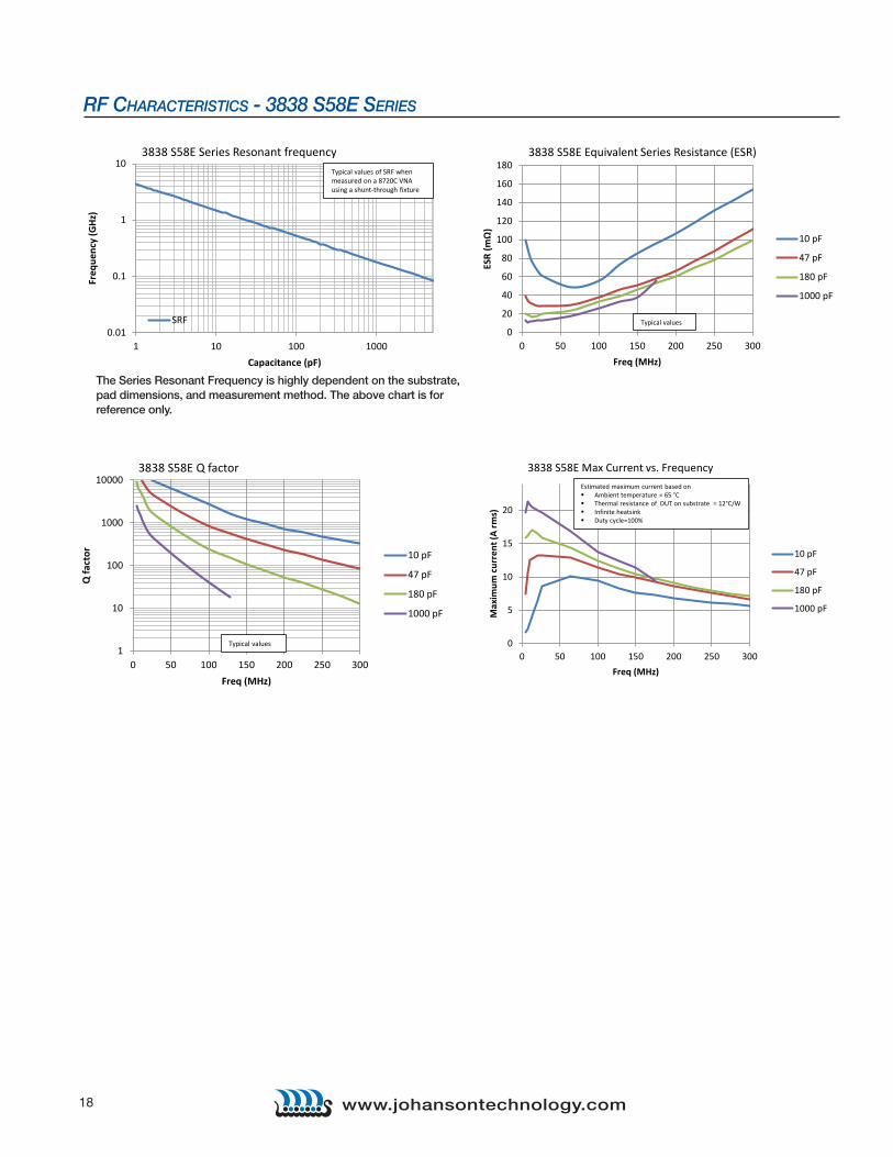
RF CHARACTERISTICS - 3838 S58E SERIES
0.01
0.1
1
10
1 10 100 1000
Freq
uenc
y (G
Hz)
Capacitance (pF)
SRF
Typical values of SRF when measured on a 8720C VNA using a shunt-through fixture
3838 S58E Series Resonant frequency 3838 S58E Equivalent Series Resistance (ESR)
0
20
40
60
80
100
120
140
160
180
0 50 100 150 200 250 300
ESR
(mΩ)
Freq (MHz)
10 pF
47 pF
180 pF
1000 pF
Typical values
3838 S58E Q factor
1
10
100
1000
10000
0 50 100 150 200 250 300
Q fa
ctor
Freq (MHz)
10 pF
47 pF
180 pF
1000 pF
Typical values
3838 S58E Max Current vs. Frequency
0
5
10
15
20
0 50 100 150 200 250 300
Max
imum
cur
rent
(A rm
s)
Freq (MHz)
10 pF
47 pF
180 pF
1000 pF
Estimated maximum current based on Ambient temperature = 65 °C Thermal resistance of DUT on substrate = 12°C/W Infinite heatsink Duty cycle=100%
The Series Resonant Frequency is highly dependent on the substrate, pad dimensions, and measurement method. The above chart is for reference only.