johnson t8000(tm95) service...
TRANSCRIPT

1
2006 Johnson T8000(TM95) SERVICE MANUAL

2
TABLE OF CONTENTSSECTION 1: MAINTENANCE PROCEDURE ………………..….…31. MAINTENANCE CHECK LIST………………………......................4 2. TENSIONING THE BELT PROCEDURE…………………..……..5-6 3. DECK RE-WAXING PROCEDURE………………………….……7-8 4. CLEAN THE GROOVES PROCEDURE…………….........................9 5. USE THE CARBON STICK TO CLEAN THE DC MOTOR……..10-11
SECTION 2: WIRING DIAGRAM INSTRUCTION…………….…...121. T8000(TM95) MCB WIRING 220V…………..………………….…..132. T8000(TM95) MCB WIRING 110V………………………………….143. T8000(TM95) MCB WIRING DEFINITION OF PIN 220V……....15-164. T8000(TM95) MCB WIRING DEFINITION OF PIN 110V…….....17-185. T8000(TM95) CONSOLE WIRING…………………………………..196. T8000(TM95) CONSOLE WIRING DEFINITION OF PIN………..20-227. T8000(TM95) ELECTRICAL BLOCK DIAGRAM FOR 220V..……23
SECTION 3: CONSOLE ENGINEER MODE………………..………..241. OPERATION MX-T3x Engineer mode..…………………………….25-28..SECTION 4: MCB LED INSTRUCTIONS…………………..…..… ….291. MCB LED place and definition for 220V……………………….…….302. MCB LED place and definition for 110V……………………..………31
SECTION 5: TROUBLESHOOTINGS……………………………….…32 1. No display on console………………………………………..………...332. Running speed is not stable…………………………………………….343. Treadmill starts to run by itself………………………………..……….354. All or some of the keys on console do not work………………….……355. Noises generated under motor cover………………...…………..….….366. Error Messages on the Console…………………………………….…..377. Error message 1 troubleshooting (1)…...……………………………....378. Error message 1 troubleshooting (2)…...……………………………....389. Error message 3,6 troubleshooting……………………............………..3910. Error message 4 troubleshooting………………………...…….……….4011. How to make sure whether the machine hand pulse can not work…....41-4212. T8000(TM95) maintenance lamp…………..…………………………..43
SECTION 6: What is the difference between 2005 TM68 & 2006 TM95…44-62

3
SECTION 1MAINTENANCE PROCEDURE

4
MAINTENANCE CHECK LIST
CleanMotor
Clean (Vacuum)Control Box
InspectRunning Belt
Inspect & Re-
waxingDeck Re-waxing
InspectCleanV Belt
InspectRunning belt Tension
TestEmergency Button
InspectCleanRear Roller
InspectCleanFront Roller
InspectCleanHandrail & Handlebar
InspectCleanDisplay Console
InspectPower Cord
ReplaceInspect Carbon Brush
InspectCleanFrame
InspectConsole Mounting Bolts
AnnualBiannualQuarterlyMonthlyWeeklyDailyItem
2006 Johnson T8000 TREADMILL
PREVENTIVE MAINTENANCE SCHEDULE

5
TENSIONING THE BELT PROCEDURE
Caution:
Over-tightening of the roller will severely shorten the life of the belt and may cause further damage to other components.
Running Belt:If when you plant your foot on the belt, you can feel a slipping sensation then the belt has stretched and is slipping across the rollers. This is a normal and common adjustment on a new treadmill. To eliminate this slipping, tension both the rear rollers Allen bolts 1/4 TURN as shown above. Try the treadmill again to check for slipping. Repeat if necessary, but NEVER TURN the roller bolts more than 1/4 turn at a time.
Perfect Tension of Running Belt: Perfect Tension of Running Belt: 0.9~1.1 lbs0.9~1.1 lbs
Frequency: Every 1 months

6
Drive Belt:If you have tensioned the running belt and are still experiencing a slipping, adjust the tension screw. Then try the treadmill again to check for slipping.

7
DECK RE-WAXING PROCEDUREFrequency: Every 1 month
Parts name: Silicon oil setParts number: SZTM74SOSPrice (USD): 0.6Use time : 1
Procedure:1. Loosen the tension bolts at both ends.2. Pull the belt with your left hand and apply the silicon in the deck
with your right hand. (The volume of silicon applied is about 40ml)
3. Tighten the tension bolts.4. Start the treadmill. Step on the treadmill belt to walk the silicon in.
Adjust the belt tension if necessary.5. With the clamp-on meter, measure the current draw of the motor.
(Clamp on either the red or the black wire.) The current should be less than 15Amps for 110V model. (less than 7.5Amps for 220V model.)
Caution:If deck is not to periodical add the waxing, between the deck and running belt will produce great friction make the deck and running belt to burn up and cut down the motor life .

8
Use the clamp-on meter (DC current-meter):
������������� ����� ���������������������������������������������������������������������������������������������������������������
With the clamp-on meter, measure the current draw of the motor. (Clamp on either the red or the black wire.) The current should be less than 15Amps for 110V model. (less than 7.5Amps for 220V model.)
���������������current limit :

9
CLEAN THE GROOVES PROCEDUREFrequency: Every 3 months
Procedure:
1.Remove the drive belt and check the grooves in belt for dirt or dust and clean it.
3Check the grooves in roller pulley for dirt or dust and clean it.
If dirty grooves in the drive belt, motor and roller pulley, there will be noises while running.
Caution:
2.Check the grooves in motor pulley for dirt or dust and clean it

10
Use the carbon stick to clean the DC motor
Frequency: Every 3 month
Caution:
If the treadmill with DC motor makes noise or running speed isn’t stable. You can use the carbon stick to clean the motor
Parts number : MTOOL- 0421 Box – 10 pcsPrice : USD 28.5

11
Carbon stick use Step :
Step 1.Take off the motor cover.
Step 2.Take off the motor carbon brush cover.
Step 3.Press “Start” key to run in the middle speed.
Step 4.Put the carbon stick to clean the motor dust inside.

12
SECTION 2WIRING DIAGRAM INSTRUCTION

13
T8000 (TM95) MCB WIRING(220V)
J1P2
P3
J2
MTR2
L2 L1
�
�
�
�
�
�
�
�
MTR1
P4 P1

14
T8000 (TM95) MCB WIRING(110V)
P2
MTR2
NEUTRAL LINE
�
�
�
�
�
�
�
MTR1P3
JP3

15
T8000(TM95) MCB WIRING DEFINITION OF PIN(220V)
P2:Elevation cable(6pin/AMP-350762-4)
Incline motor does turn on powerCOM6
Incline motor does move to downDOWN5
Incline motor does move to upUP4
Incline place signal test groundELVR_GND3
Incline place signalELVR_POT2
Incline place signal test power ELVR_+5V1
DefinitionNamePin
1
2
JP1
3
4
5
6

16
P3: 8-pin console cable
DefinitionNamePin
Console groundSGND8
Incline place signalELVR_POT7
Incline place signal test groundELVR_GND6
Incline place signal test powerELVR_+55
Console provide for incline motor UP signalUP4
Console provide for incline motor DOWN signalDOWN3
Speed sensor provide signalRPM2
Console for MCB of the PWM signal PWM1
1 8
J3
P4: 6-pin console cable
J1
DefinitionNamePin
Console groundSGND4,5,6
Console power+121,2,3
1 6

17
T8000(TM95) MCB WIRING DEFINITION OF PIN(110V)
P2:Elevation cable(6pin/AMP-350762-4)
Incline motor does turn on powerCOM6
Incline motor does move to downDOWN5
Incline motor does move to upUP4
Incline place signal test groundELVR_GND3
Incline place signalELVR_POT2
Incline place signal test power ELVR_+5V1
DefinitionNamePin
1
2
JP1
3
4
5
6

18
P3: 20-pin console cable
No UseN/A19
DefinitionNamePin
No UseN/A20
No UseN/A18
No UseN/A17
No UseN/A16
Drive motor signalMOTOR15
Console provide for incline motor DOWN signalDOWN14
Console provide for incline motor UP signalUP13
Console power+1212
Console power+1211
Console power+1210
Console for MCB of the PWM signalPWM9
Console groundGND8
Console groundGND7
Speed sensor provide signalRPM6
Incline place signal test power(+5V)VCC5
Incline place signalELE4
Console groundGND3
No UseN/A2
Console groundGND1
1220
19
P3

19
�
�
�
�
�
T8000(TM95) CONSOLE WIRING
J13 J6J12
�
�
�
�
�
J8 J7 J10 J3J5
C-SAFE
J14

20
T8000(TM95) CONSOLE WIRING DEFINITION OF PIN
J6:20-pin console cable
No UseN/A19
DefinitionNamePin
No UseN/A20
No UseN/A18
No UseN/A17
No UseN/A16
Drive motor signalMOTOR15
Console provide for incline motor DOWN signalDOWN14
Console provide for incline motor UP signalUP13
Console power+1212
Console power+1211
Console power+1210
Console for MCB of the PWM signalPWM9
Console groundGND8
Console groundGND7
Speed sensor provide signalRPM6
Incline place signal test power(+5V)VCC5
Incline place signalN/A4
Console groundN/A3
No UseN/A2
Console groundGND1
1220
19
J6

21
J13: 8-pin console cable
DefinitionNamePin
Console groundSGND8
Incline place signalELVR_POT7
Incline place signal test groundELVR_GND6
Incline place signal test powerELVR_+55
Console provide for incline motor UP signalUP4
Console provide for incline motor DOWN signalDOWN3
Speed sensor provide signalRPM2
Console for MCB of the PWM signal PWM1
1 8
J13
J12: 6-pin console cable
J12
DefinitionNamePin
Console groundSGND4,5,6
Console power+121,2,3
1 6

22
DefinitionNamePin
Console groundGND2
SAFE_KEYSAFE1
J5:Safe key wire
J5
1 2
J7:Hand sensor wireJ8:Pulse board wire
J7J8
1 2 1 4
Console power (+5V)VCC2
Pulse Board signalHR23
DefinitionNamePin
Console groundGND1
Console power (+5V)VCC3
Hand sensor signalHR12
Console power (+5V)VCC4
DefinitionNamePin
Console groundGND1

23
T8000(TM95) Electrical block diagram for 220V

24
SECTION 3CONSOLE ENGINEER MODE

25
T8000 OPERATION MANUAL- Engineer mode
How to enter into the engineering mode?
1. Press & Hold both “ELEVATION ” and “SPEED ” at the same time
for 3-5 sec. Then, the display will show “MANAGER MENU”.
2. Press the "ELEVATION or " to select you want and press the “SELECT" key enter.
Engineer mode setting

26
To edit the selected screenSELECT
To save the selected variableSTART
Arrow to set the variableSLOW
Arrow to set the variableFAST
Arrows to scroll through the different screensDOWN
Arrows to scroll through the different screensUP
functionkey name
KEY BEHALE FUNCTION
The list manager’s custom setting

27
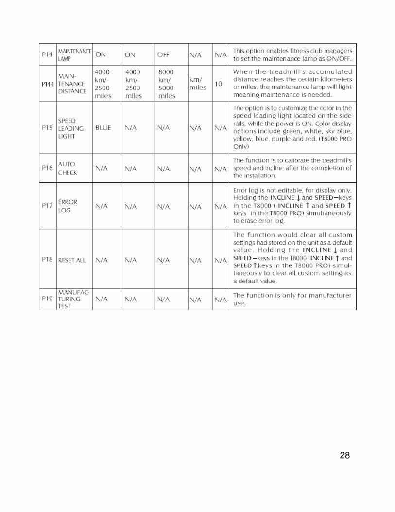
28

29
SECTION 4
MCB LED INSTRUCTIONS

30
T8000(TM95) MCB LED PLACE AND DEFINITION FOR 220V
� +18------MCB Power indicator light
� V_CON-------Indicates if Console Voltage Supply is present.
� PWM------Console PWM signal light
� UP----- Indicates if the upper console is commanding Elevation UP
� DOWN---- Indicates if the upper console is commanding Elevation DOWN.
� SPD_SENSR--- Indicates the motor is moving via the encoder's feedbackby blinking.
� I_LIMIT---- Over the 16A current limit time-out for 3’s has occurred.
� MTR_AC----MOTOR power indicator light.
� MOTOR---- MOTOR running light.
� MTR_SHRT---- MCB damage.
MTR_SHRT
MOTOR
MTR_AC
I_LIMIT+18PWMSPD_SENSR
V_CON
DOWN
UP

31
T8000(TM95) MCB LED PLACE AND DEFINITION FOR 110V
� +18------MCB Power indicator light
� AC---- Indicates if the DC Buss is Energized (Voltage Present).
� V_CON-------Indicates if Console Voltage Supply is present.
� PWM------Console PWM signal light
� UP----- Indicates if the upper console is commanding Elevation UP
� DOWN---- Indicates if the upper console is commanding Elevation DOWN.
� SPD_SENSR--- Indicates the motor is moving via the encoder's feedbackby blinking.
� I_LIMIT---- Over the 16A current limit time-out for 3’s has occurred.
� MTR_AC----MOTOR power indicator light.
� MOTOR---- MOTOR running light.
� MTR_SHRT---- MCB damage.
MTR_SHRT
MOTOR
MTR_AC
I_LIMIT+18PWMSPD_SENSR
V_CON
UP
DOWN
AC

32
SECTION 5
TROUBLESHOOTINGS

33
No display on console
Possible causes:
1. Breaker is damaged.
2. ON/OFF switch is damaged.
3. MCB is damaged
4. 6-pin console cable is damaged
5. PCB is damaged
Fix:1. Inspect the circuit breaker to see if it has tripped off.
(If it is tripped off….like diagram B, reset the breaker. And check which part is short-circuited. Then replace the short-circuited part.)
A B
2. The switch is turned to the "ON" position.( If the switch light isn't lit, replace the switch.)
2-1 Verify wire connection L1 & L2 on the MCB.
(Please refer the” MCB WIRING” ……page 14)3. Verify the MCB whether supply the +12VDC for console.
(Please refer the” MCB LED V_CON have light” ……page 30)4. Replace 6-pin console cable .5. Replace PCB
34
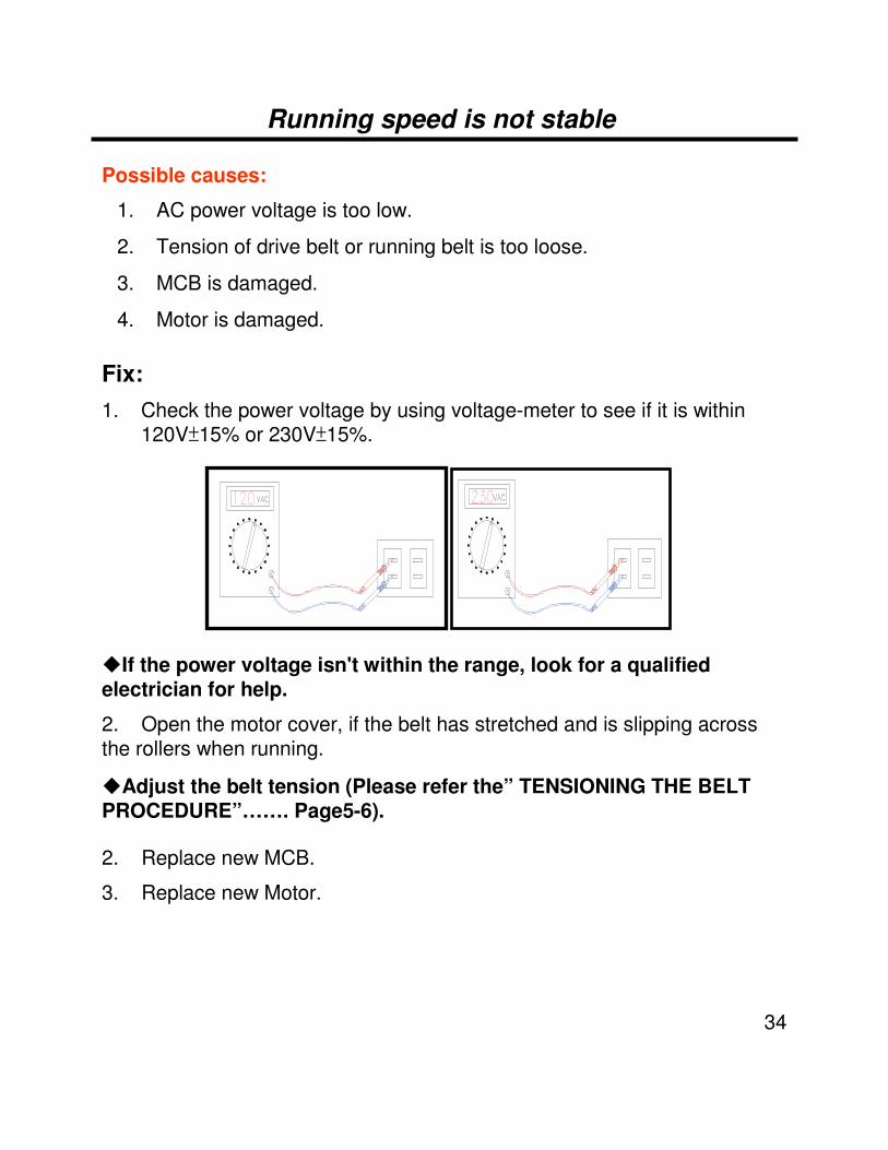
Running speed is not stable
Possible causes:
1. AC power voltage is too low.
2. Tension of drive belt or running belt is too loose.
3. MCB is damaged.
4. Motor is damaged.
Fix:1. Check the power voltage by using voltage-meter to see if it is within
120V 15% or 230V 15%.
�If the power voltage isn't within the range, look for a qualified electrician for help.
2. Open the motor cover, if the belt has stretched and is slipping across the rollers when running.
�Adjust the belt tension (Please refer the” TENSIONING THE BELT PROCEDURE”……. Page5-6).
2. Replace new MCB.
3. Replace new Motor.

35
Treadmill starts to run by itself
Possible causes:
1. The console cable is broken.
2. PCB is out of order.
3. MCB is out of order.
Fix:1. Replace the console cable with a new one.
2. Replace the PCB.
3. Replace the MCB.
All or some of the keys on console do not work
Possible causes:
1. Keypad connecting plug is not fit-in properly.
2. Keypad is damaged.
3. PCB is damaged.
Fix:1. Disconnect the keypad and replace the keypad, and check again.
2. Replace the keypad.
3. Replace the PCB.

36
Noises generated under motor cover
Possible causes:
1. The running belt tension is adjusted too tight.
2. The bearing of front roller is not installed correctly.
3. Dirty grooves of drive belt.
4. The motor is damaged.
Fix:1. Adjust the belt tension so that the belt does not start slipping and
then check if the noise has disappeared.
�Let the treadmill run, without using it, for at least 5 days because sometimes the bearing will settle and become quiet then check if the noise has disappeared.
2. Replace the front roller with a new one to see if the noise disappear.
3. Remove drive-belt and check the grooves in belt for dirt or dust and clean if necessary. Clean also the motor pulley and the roller pulley grooves and check if the noise has disappeared.
4. The motor bearing is damaged.(Please refer the “Use the carbon stick to clean the DC motor”……page 10-11)
�Replace the motor.

37
Error Messages on the Console
Incline motor not to movement E3
Incline motor the signal not answer E6
RPM Detect the mistake (Only occur on Auto Check) E4
Treadmill will not start E1
Definition Error
Error message 1 troubleshooting (1)
[Symptom 1 of treadmill will have start ]Press start and after 10 sec. the LED displaywill show “Error 1”
[Cause]The speed sensor can’t sense the speed
[Solution]1. Check the connector condition of the speed
sensor cable.
2. Replace the speed sensor.
3. Check the magnet on the front roller if it’s
too far away from the speed sensor
Magnet
Speed sensor
Check the connector MCB and Speed sensor cable

38
Error message 1 troubleshooting(2)
[Symptom 2 of treadmill will not start ]Press start and after 10 sec. the LED display will show “Error 1”
[Cause]
1. MCB is damaged.
2. 8-pin console cable is damaged.
3. PCB is damaged.
4. Motor is damaged.
[Solution]1. Open motor cover, verify wire connection BL [Motor wire (black)] and RED
[Motor wire (red)] on the MCB then plug in the power cord and turn on the power switch. Then press “START“ button.
2. Open MCB cover, connect all cable to MCB again turn on the power, verify the LED indicator of +18 LED is to glitter.
(If that +18 LED is not glitter, replace MCB)
3. Press “Start” key, verify the LED indicator of PWM LED is to lit.
(If that PWM LED is not lit, replace console cable. If PWM LED is still not lit, replace PCB. )
4. Replace Motor.
PWM

39
[Symptom]Press start then the console display show “Error 3 or 6“
[Cause]
1. The 8-pin console cable is damaged.
2. Incline motor is damaged.
3. PCB is damaged.
4. MCB is damaged.
5. The incline setting is not correct.
[Solution]1. Please check the incline motor cable whether to inset MCB.
2. Check the console signal whether transmission to MCB, you can refer to MCB LED UP and DOWN. If LED not light please check the console cable and console. If LED have light please replace the incline motor
3. If display still show “Error 3 or 6“, please replace the incline motor.
4. If display still show “Error 3 or 6“, please replace the PCB.
5. If display still show “Error 3 or 6“, please replace the MCB.
6. Enter Engineering Mode to renew the Auto-calibration( Engineer mode P16) elevation parameter (Please refer the page 27) .
Error message 3,6 troubleshooting
MCB LED UP and DOWN LED whether have light.
40
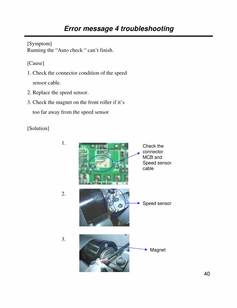
Error message 4 troubleshooting
[Symptom]Running the “Auto check “ can’t finish.
[Cause]
1. Check the connector condition of the speed
sensor cable.
2. Replace the speed sensor.
3. Check the magnet on the front roller if it’s
too far away from the speed sensor
[Solution]
Magnet
Speed sensor
Check the connector MCB and Speed sensor cable
1.
2.
3.
41
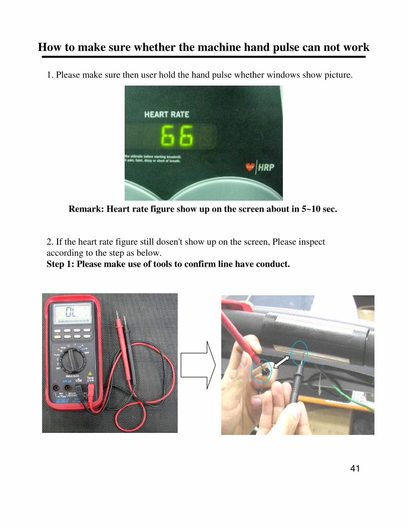
How to make sure whether the machine hand pulse can not work
1. Please make sure then user hold the hand pulse whether windows show picture.
Remark: Heart rate figure show up on the screen about in 5~10 sec.
2. If the heart rate figure still dosen't show up on the screen, Please inspect according to the step as below.Step 1: Please make use of tools to confirm line have conduct.

42
Step 2: Please check the connection.
Check whether the heart rate cable is touching hand pulst metal (both of left hand and right hand).
Besides the other side of the heart rate cable should be connected with HR board.
Step 3: If you can't find any problem with above step, and the heart rate figure still can't showup, Please replace the heart rate board.

43
1. When the distance accumulate to 5000KM the lamp will be lighted in blue.
2. There has to do some maintenance 2.1 Test the running belt if loose or not?2.2 Lubricate the running belt2.3 Remove the motor cover and clean the dust inside2.4 Clean the frame2.5 Check the running belt is in the center or not.
3. There can hold “DOWN" & “SLOW" Key for 3 seconds to turn off the light
Maintenance lamp
Johnson T8000(TM95) maintenance lamp

44
SECTION 6What is the difference between
2005 TM68 & 2006 TM95

45
1.Elevation motor
Not limit switch Add the limit switch
OLD NEW
Parts number :
SCD401022A(IE)
028512-A (SAP)
Parts number :
SCD401023A(IE)
038979-A (SAP)

46
2.PCB
OLD NEW
Parts number :
SJTD01002BI(IE)
013749-BI (SAP)
Parts number :
SJTD01030AA(IE)
038443-AA (SAP)
Add the Quick key function
47
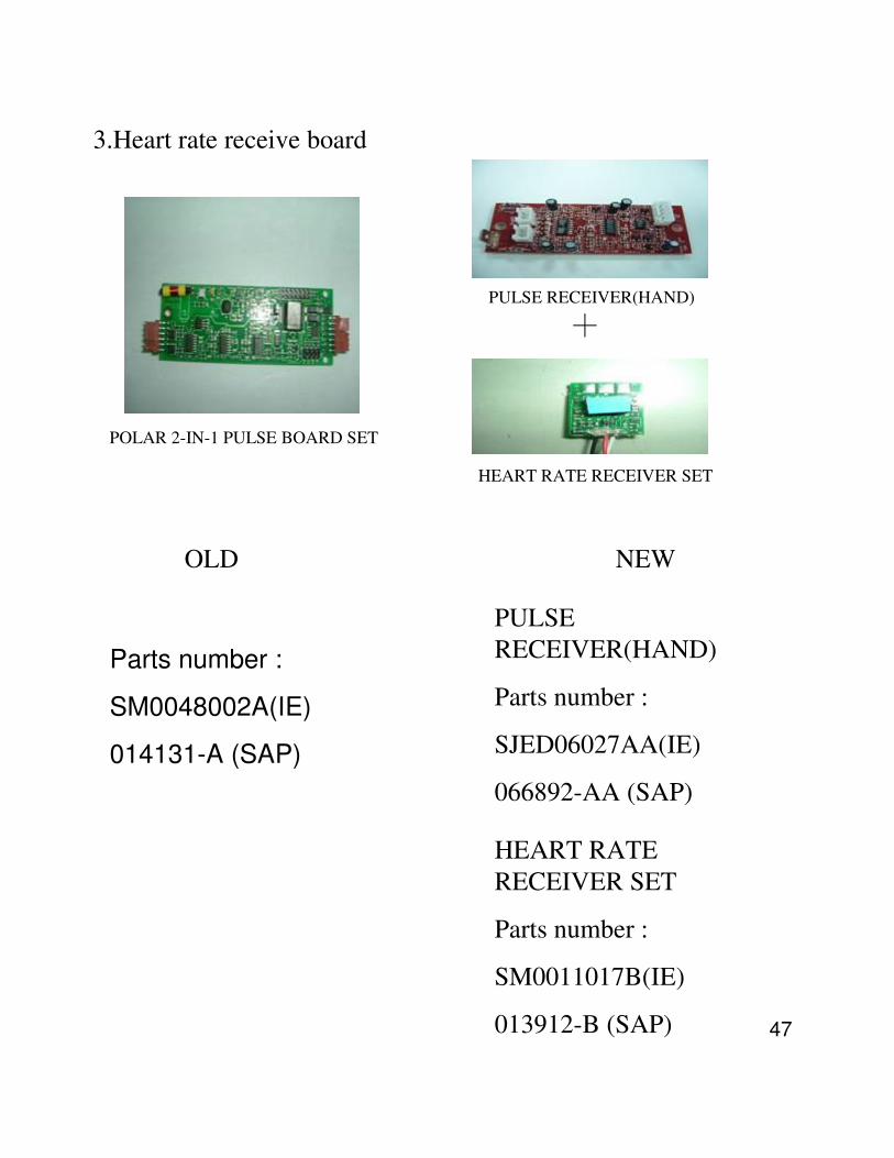
3.Heart rate receive board
OLD NEW
Parts number :
SM0048002A(IE)
014131-A (SAP)
PULSE RECEIVER(HAND)
Parts number :
SJED06027AA(IE)
066892-AA (SAP)
HEART RATE RECEIVER SET
PULSE RECEIVER(HAND)
POLAR 2-IN-1 PULSE BOARD SET
HEART RATE RECEIVER SET
Parts number :
SM0011017B(IE)
013912-B (SAP)

48
4. LEFT KEY PCB
OLD NEW
Parts number :
SJTD03001BA(IE)
013771-BA(SAP)
Parts number :
SJTD03016AA(IE)
038450-AA (SAP)
Add the Quick key function

49
5. RIGHT KEY PCB
OLD NEW
Parts number :
SJTD04001BA(IE)
013778-BA(SAP)
Parts number :
SJTD04003AA(IE)
038452-AA (SAP)
Add the Quick key function

50
6. Left CONSOLE L HANDLEBAR ( NEW)
1CONSOLE L HANDLEBAR(process);TM95-2KM;SR0008005AAN03
1Fast Key Set;T8000 TM95;TM95-W13SJTD03017BAW13
1Quick Key BASE MB06C5010DAN43
1Elevation KEY OVERLAY MC0601828BN45
QTYDescriptionParts number Item

51
7. Right CONSOLE L HANDLEBAR ( NEW)
1CONSOLE R HANDLEBAR(process);TM95-2KM;SR0008006AAN04
1Fast Key Set;T8000 TM95;TM95-W13SJTD03017BAW13
1Quick Key BASE MB06C5010DAN43
1Speed KEY OVERLAY MC0601829BN46
QTYDescriptionParts number Item

52
8. Power Fix Plate
OLD NEW
Parts number :
MJ1008021A(IE)
055980-A (SAP)
Welding on frame

53
9. MCB PLATE;SPHC 3.0t(New plate)
Parts number :
MJ1082074B(IE)
055982-B (SAP)

54
10. Increase regular slice of TV shelf (NEW)

55
11. UP Console Wire (NEW)
Parts number :
MC0501208A(IE)
066894-A (SAP)

56
12. Down Console Wire (NEW)
Parts number :
MC0501209A(IE)
066895-A (SAP)

57
13. Fast Key Wire (UP) (NEW)
Parts number :
MC0507018A(IE)
038985-A (SAP)

58
14. Fast Key Wire (Below); (NEW)
Parts number :
MC0507019A(IE)
038986-A (SAP)

59
15. Fast Key Power Wire (NEW)
Parts number :
MC0507020B(IE)
038987-B (SAP)

60
16. Fast Key Wire; (NEW)
Parts number :
MC0507021A(IE)
038988-A(SAP)

61
17. Pulse IRE SET; (NEW)
Parts number :
SM0062001AA(IE)
066890-AA(SAP)
62
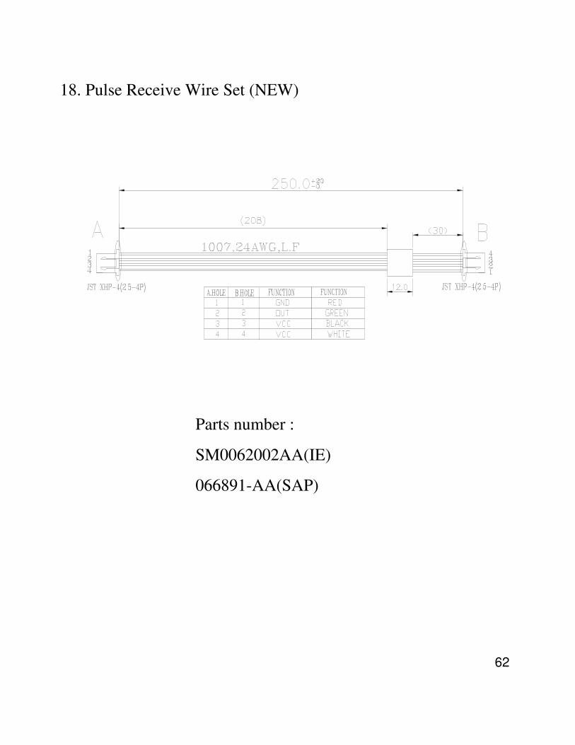
18. Pulse Receive Wire Set (NEW)
Parts number :
SM0062002AA(IE)
066891-AA(SAP)