journal of industrial aerodynamics, 4 (1979) 371- … · 3/4/1979 · *paper presented at the 3rd...
TRANSCRIPT

Journal of Industrial Aerodynamics, 4 (1979) 371--389 371 © Elsevier Scientific Publishing Company, Amsterdam -- Printed in The Netherlands
WIND SHELTERS
J. GANDEMER*
Section ADYM, C.S.T.B., Nantes (France)
Summary
The aerodynamics of wind breaks is studied in a simulated boundary layer. Flow patterns and shelter effects in the lee of different fences are described and discussed in terms of effi- ciency relating to pedestrian comfort.
Based on the generally accepted critical level of discomfort, and the corresponding dis- comfort wind frequencies, we suggest a shelter parameter. The results downstream are given in horizontal planes by nets of isocurves (isotachs, isoturbs, isoshelters) with specific levels in relation with discomfort wind frequencies.
The influence of the permeability, the shape, the sizes, the wake ventilation are discussed and new designs are suggested: for instance, the association of two wind breaks seems to be very good; the high horizontal speed gradient at the corner can be easily reduced as can the overspeed, etc. In fact, depending both upon the comfort level people want and upon the area (downstream) the "best" protection will not be given by the same wind break aerody- namics.
The influence of the vegetation on the wind shelter (full scale experimentation) is also described. The discussion is in terms of the analysis of energy spectra.
Introduction
The aim of our investigation on windbreaks is to provide town-planning de- signers with practical methods of controlling the flow of air near the ground from the point of view of the comfor t of the pedestrian.
It has been possible to show [1] the important effect of certain factors on the characteristics (flow, speed, turbulence, etc.) of the wake of the windbreak structure, in particular: the dimensions of the windbreak in relation to the scale of the wind, its shape, its permeability (in terms of porosity, pressure drop or drag) and the associated distribution, and the flexibility, if any, of its constitu- ent parts. Apart f rom the nature of the screen itself, the characteristics of the incident wind (vertical gradient of mean speed, turbulence) its incidence and the presence of a near environment are going to play a part.
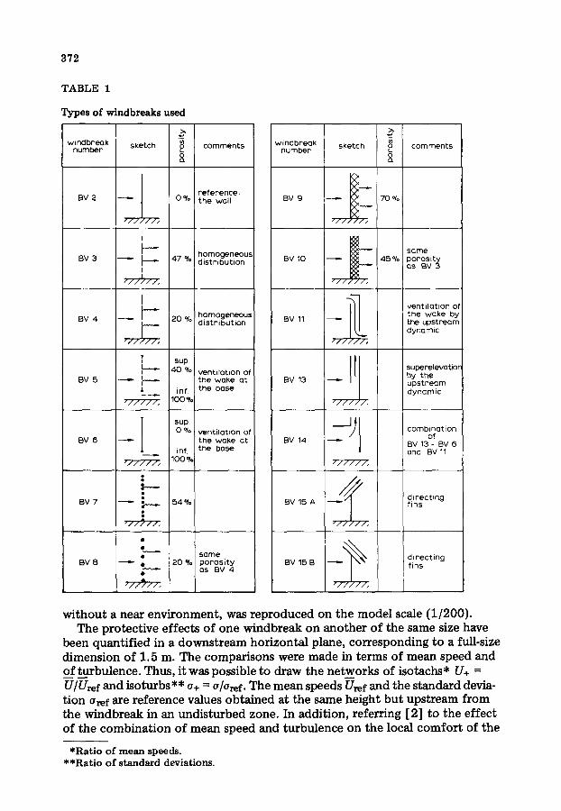
The design of the various types of windbreak studied has been governed by the aerodynamic effects sought downstream from the structure. Table 1 indi- cates the types of screens examined. The tests were made in a wind tunnel with a turbulent boundary layer, where a wind of the type found in the country,
*Paper presented at the 3rd Colloquium on Industrial Aerodynamics, Aachen, June 14--16, 1978.
372
TABLE 1
Types of windbreaks used
windbreak number sketch
o e~
comments
BV 2
/ / / / / / /
I L-- . . . I
BV3 ~ I I I I / / / / / / .
I
B V 4 ~ ~ ' ~
V "//I//,
L-..-- I
BV 5 I
r i l l / l ,
BV 6
".//II/,
BV7 ~ : e ~
. I / / ~ 1 1 ,
BV 8
z / / ~ . / / ,
r e f e r e n c e : 0 % t h e wall
homogeneous 47 % dis t r ibut ion
homogeneous 20 % dis t r ibu t ion
SUp.
40 % ventilation of the woke at
inf, the base 100 %
sup 0 % vent i la t ion of
the w a k e at inf. the bose
100%
54 %
s a m e 20 % p o r o s i t y
as BV 4
windbreak sketch number
V BV 9 ~ ~ _ _
- / - / /
BV 10 ~
-//, "//,
BV 11 ~ I
/ / / , / / ,
BV 13 , ~ 1 l
/ / / / , / ,
BV 14
/ / / / / / ,
BV 15 A
/ "/////,
BV 15 B ~
/ / / / / / / ,
corn ments
70%
same 45% p o r o s i t y
as BV 3
vent i la t ion of t h e wake by the upstream dynamic
superelevatior by the u p s t r e a m dynamic
combinat ion of
BV 13 - BV 6 and BV 11
directing f ins
d i rec t ing f ins
without a near environment, was reproduced on the model scale (1 /200) . The protective effects of one windbreak on another of the same size have
been quantified in a downstream horizontal plane, corresponding to a full-size dimension of 1.5 m. The comparisons were made in terms of mean speed and of turbulence. Thus, it was possible to draw the networks of isotachs* U+ = V/Uref and isoturbs** o+ = a/Oref. T h e mean speeds Vref and the standard devia- t ion Oref are reference values obtained at the same height but upstream from the windbreak in an undisturbed zone. In addition, referring [ 2] to the effect of the combinat ion of mean speed and turbulence on the local comfort of the
*Ratio o f mean speeds. **Ratio o f standard deviations.
373
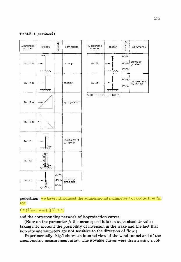
TABLE I (continued)
windbreqk sketch number
-I BV 16 A
//////,
BV 16 B
/ / / / / / ,
/
BV 17 A ~ /
BV 17 B --
BV 16
comments L 0
canopy
!canopy
spr ing-board
complement to BV 11
8 BV 19 ~ !
" / , / / / / , i
I I 2 0 % I i
BV 20 ~ i 40 fro' poros i t y - ) (50 % grad ien t
"//~//,
windbreak sketch number
BV 22 ~
"//~//. I
BV 26 i I i //////.
scale h = 5 m , L = 1 2 0 m
~) comments L o
6O %
p o r o s i t y 40 % grad ient
20 %
50% complement to BV 22
20 %
pedestrian, we have introduced the adimensional parameter f or protection fac tar:
f = (Uref + Oref)/(I UI + o)
and the corresponding network of isoprotection curves. (Note on the parameter f: the mean speed is taken as an absolute value,
taking into account the possibility of inversion in the wake and the fact that hot-wire anemometers are not sensitive to the direction of f low.)
Experimentally, Fig. 1 shows an internal view of the wind tunnel and of the anemometric measurement array. The isovalue curves were drawn using a col-

374
Fig.1. Internal view of the wind tunnel and of the anemometric measurement array.
lecting and t rea tment system connected to a drawing table. As a preliminary, "calibrations" were necessary; in particular, that of the speed distribution in the experimental tunnel without the windbreak structure and that of the direc- tional effect on the hot wires.
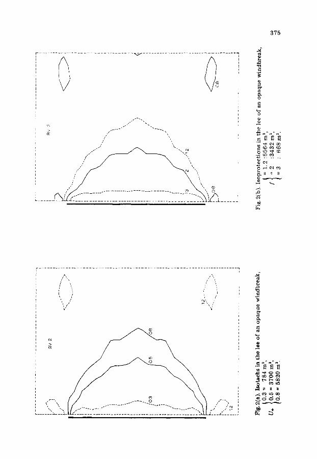
Figure 2 gives an example of two networks of isovalue curves for an opaque windbreak. When comparing the different arrangements, not all the isovalues were analysed. If one refers to the generally accepted threshold of discomfort [2] (5 m/s, 20% of turbulence) one will have, in France, for climatically ex- posed zones, an annual reduction in the frequency of discomfort of 30% for isoprotections such that f i> 1.2, of 80% for isoprotections such that f /> 2 and practically 99% for isoprotections such that f ~> 3. For the same amounts of reduction, the thresholds of the isotachs are respectively U÷ = 0.8--0.5 and 0.3.
To condense our results and to facilitate comment on them we have recapitu- lated in Fig.3, for the different windbreaks, the areas (plane z = 1.5 m) of the isovalues. The protected area between the back of the windbreak and the iso- value (U+ = 0.8--0.5 and 0.3 or f= 1.2--2 and 3) are indexed by the dimensions of the windbreak: height 5 m, width L = 120 m facing the transverse scale of the wind (A -~ 40 m). In addition, they are to be compared with the reference area (upstream rectangle 25 h × 35 h = 21 120 m 2) and have all been obtained for an orthogonal incidence of the open-country wind (Fig.3). Lastly, in our comments, our point of reference will always be the thin opaque windbreak (solid wall) and we shall conventionally define the "near wake" as the down- stream space broadly contained between 0 and 10 h; beyond that, the wake will be described as "dis tant" .
The main conclusions from our investigations are presented in the following sections.
375
/ ," \
11 x.
f " . ,
0
~ II II li
N
~2
It 04 ~, L f \ /
c~
0
ID
o~
I i 11 tl ,,...4, ¢~ Ue~ O0 ~ d d d

376
II °8 12 0 0 0 U . O,5
,..n 0 . 3
8
o "o 1 0 0 0 0
2 r,
8OOO
6000
4 0 0 0
2 0 0 0
0 : 1 . 2 [ I '1 ,5 m
wtnc~ ~ ~
I1 2 ~ h = 125 m I t
I
A , 1
I
o
, / o
- -.~, - ,~'~ - - +-:.-~q , - - - p ' . ~ , " f " ~ ~,~+ - I- - - , ~ . . . . . . .~ ~ - A,,, /~ B ,~-- , " f, I | ',', / ,'2~, . , . , y r i
I,, ,, ~t , | ',~:.o' : : . ~ ' ' " ' lit ~ I i~1 I / ! , , " ~' I X II I ' X I
, , , ' , : ' 4 , .~, / ~ I * ' ~ . . . , ~ , / ,,,I - - ~ ~ ', ,
,, . . . . . . . -~-, ;~ I
i
/\ I
! I XI i j__L~ I_
7 e x ' ~ - - - I I i t I ' , ' , ' :,, '
I
I i ~ i i
- T y p e o f w i n d b r e a k
Fig.3. Pro tec ted areas (S in m=) be tween the back of the d i f ferent windbreaks and the isovalues (U+ or f).
Influence of the shape and thickness of an opaque windbreak (BV 2, BV 16, and BV 17, Fig.4)
With a rectilinear windbreak with a thickness of the same order as its height (negligible compared with the scale of the wind), the wind passes over the barrier practically independently of its shape. In some instances, the influence of this "thickness ' may be unfavourable in the area of the near wake (BV 16 A). Hence, we entirely recommend the thin opaque windbreak.
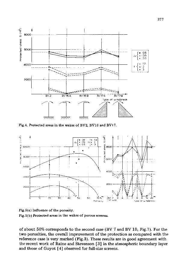
Influence of the porosity of thin rigid screens (BV 3, BV 4, BV 5, BV 7, BV 8, BV 9, BV 10, BV 20, Fig.5)
It is found that there is a systematic protection effect with porous screens, especially in the distant wake.
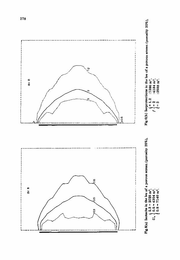
With homogeneous porosity, the opt imum value will differ depending on whether the aim is a high degree of comfor t (reduction of the frequency of dis- comfort by 80% -- isovalue U+ = 0.3 and 0.5 f = 2 and 3) or less high (reduc- tion of the frequency of discomfort by 30% or U+ = 0.8 and f = 1.2) over the maximum area. Thus a homogeneous porosity of the order of 20% is an op- t imum for the first case (BV 4 and BV 8, Fig.6), whilst a homogeneous porosity
3 7 7
~ 8 o o o
I.. o
~ 6 o o o , . . . . . . . . . . . . . . , - - - -
D_
4OOO
BV 2 BV 16 A BV 16 B BV 17A BV 17 B
Type of w indb reak
I i 0 8 U+ 0 5 0 3
f 2
3
Fig.4. Protected areas in the wakes o f BV2, B V 1 6 and BV17.
I [ , : o 3 L , , 3 / ~ I ~ 1 0 0 0 0 , I / - - ~ 8 0 ( : ] 0 - - - . . . .
! i / I "- \ "6 6ooo / /~r
~oool// ~ . . . . ~- . . . . . . ~ . . . . . . + - - - + - - - - X . - I i • ' / i I i , I o o o + , . .
I i I " E ~ 1 20001 ] li
Porosity wall
Fig.5(a) Inf luence o f the porosity.
Fig. 5(b) Protected areas in the wakes o f porous screens.
/
i I o
r~, /A ~
~,' /t I ,'IV, I / i I ,,,~,,, , p
//!, ' ,~i, I r
7 8 9 10 20 - Type of vvl nd break
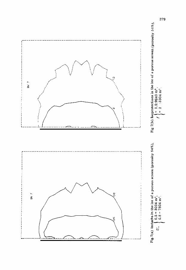
of about 50% corresponds to the second case (BV 7 and BV 10, Fig.7). For the two porosities, the overall improvement of the protection as compared with the reference case is very marked (Fig.3). These results are in good agreement with the recent work of Raine and Stevenson [3] in the atmospheric boundary layer and those of Guyot [4] observed for full-size screens.
378
/
O0 , , .
. J •.~
1 , ! ~ 1 , I I / ,,~, 0 L . . . . . . . A_'.l! . . . . . . . . . . . . . . . . . . . . . . . . . . . . . . . . . . . . . . . . . . . . . . . . . . . : ~ I t . A _ . . . . . . . .
v
0
I:I ° ~
0
0 It 11 II
L . . . . . . . . . . . . . . . ,.,i
0 I lh
v
¢0
0
.I11_ II II II O ~ a O ~ d d
0
r ~
>~
(
/
i t
J
379 .-z.
0
e~
0
0 ~1 ¢'0 4a ~ / , i "
I1 II 0 " " ' , " ' *
t",-
t 0
i . . . . . . . . . . . .
R 0
0
.1~ 11 11 ~ L-'3 oO
0

380
If the lower limit of the porous screen is the opaque screen, the upper limit is around 70% porosity, beyond which there is no effect in the near wake (identi- cal with the case where there is no screen) and the gains obtained in the distant wake are much reduced.
(Note: The notion to be introduced would be rather that of drag which is difficult to quantify, especially on the full scale. As a first approximation, and with a view to application, we have expressed our results in terms of geometri- cal porosity associated with a distribution.)
The distribution of the porosity has a direct effect on the nature of the wake (Fig.8). Thus, a windbreak with a porosity increasing with height (20%--60%; BV 22) will have a protective effect scarcely better (the immediate wake ex- cepted) than that of an opaque windbreak). On the other hand, a windbreak with decreasing porosity (609'0--20%; BV 20) will have a notable protective ef- fect in the distant wake. The ventilation of the wake at the base appears to be relatively decisive. Moreover, this point is confirmed for the opaque windbreaks pierced at their base (on different principles BV 6 and BV 11), for which the efficiency of the protection approaches that of windbreaks with 50% porosity.
In consequence, only windbreaks with a porosity decreasing with height and with a (spatially) average porosity approaching the values 20% and 50% can equal the corresponding homogeneous windbreaks.
8000 u}
t~
L. o
"~ 6 0 0 0
I1.
4000
i:: ---------'-:i;;"
'::'-'-~ ~. - Z-- :-~-:-~,-~. _-_------Z- ~- ~. i . . . .
BV 2 BV 20 BV 22 BV ~ Bv f l l
Type of windbr'eak
7H..27, -.-~~'7,,,.
fi : 0.8
i . : 0.5 0 3
Fig. 8. Inf luence of the dis t r ibut ion of the porosi ty on the protected areas.

381
Influence of directing fins (Fig.9)
In a certain number of windbreaks, we have tried to use the energy of the incident wind as it passes the screen. Thus very simple fins (see Table 1) were provided at the top or on the front face of the windbreak (BV 11, BV 13, BV 14, BV 15, BV 18, BV 28).
By measures of this type, it is possible to improve either the near wake by displacing downstream the reattachment point of the flow (BV 15 A) or the distant wake by ventilation of the wake (BV 11--BV 15 on the condition that too much of the energy is not taken as with BV 18). The working of windbreak 11 (connection of the over pressure of the wind at the top with the depression downstream at the base) shows a notable improvement in the whole of the wake as compared with the opaque wall and can be recommended.
The direction of the rise of the flow upstream from the obstacle leads to a "dynamic" superelevation of the windbreak (BV 13) and, in consequence, an increase in the areas protected. Without introducing substantial gains, the action is beneficial throughout the wake and could be developed.
(Remark: A general observation, if one hopes to use the energy of the inci- dent wind, is that the windbreak should be as opaque as possible. Any combi- ned guidance-porosity system has a tendency for the beneficial effects of the two principles to cancel one another.)
o 0 8
i ÷ 0.5
0 3 4 o 0 o ; . . . .
. . . . . . E -L - - - : --= - - .7 . : - - ~ ,_:_22. 2 = : i : : L L : L . . ; = ' ~ z ~.:.~ " ' . . . . . . . ~ - 22
":'i-.. 3
2000 ~! "/
::'" ""i: :::::i ;''~ '" BV2 BV11 BV13 BV14 BV15A BV15B BV18 B V 2 8 - - "
Type of wmclbreoK
Fig. 9. I n f l u e n c e of d i rec t ing f ins on the p r o t e c t e d areas.

382
C o m e r e f f e c t
When the wind goes round a windbreak of low permeabili ty (20% and opaque) an excess speed develops at the comers and also a large turbulence which encroaches on a part of the sheltered zone. Different types of t reatment have been proposed, always keeping length L = 120 m the same (Fig.10; wind- breaks BV 34, BV 24, BV 28).
Two arrangements are of particular interest: The first consists of eliminating the anomaly of excess speed by going upwind at each end for about once the height of the windbreak with a porous element of 20% permeabili ty (Fig. l l (a)) . The marked horizontal speed gradient is reduced at the turning of the corner and the excess speed is eliminated.
(Note: Prolonging the porous "cheeks" downwind (BV 28) does nothing to increase the area of the protec ted zones.)
The second arrangement consists of placing lateral guiding fins which widen the windbreak and, in consequence, increase (at equal dimensions) the protec- ted zones. This arrangement (F ig . l l (b ) ) throws the excess speed anomaly (at the turning of the comer) slightly downstream.
The wish to suppress the parasitic effect in the neighbourhood of the comer, the gain in the area sheltered, or again the bet ter use of the sheltered area from a rectangular rather than a semi-circular shape, lead us to envisage additional experiments on this point.
8 0 0 0 ~ r
a ,¢F "¢~.
60o01 ,~ """h,*. ~ ~o
~+" i \ \ % oool I . . . . =a, ,-. I " , t !
2ooo .-:.- T ',',,
BV 2 BV 4 BV 23 BV 24 BV 14 BV 28
Type of windbreak
u ~, L_2~_ ~ ~ I /
Fig. i 0 . Inf luence o f the aerodynamic o f the corners on the protected areas.
{i : 0.8
U÷ : 0.5 : 0,3
{i ~12 f ~2 : 3

383
Fig.ll.(a) Porous element upstream of the corner, (b) Lateral guiding fins.
Investigation of the association of windbreaks (Table 2, Fig.12; BV 21, BV 23, BV 24, and comparison with BV 27)
The areas having good protection (iso f = 2 or 3) have, in general, behind the screen, a shape approximating to a semi-ellipse (of which the major axis is that of the screen). With a view to transforming these areas into rectangles, which are more functional in use, we have sought the opt imum spacing of two wind- breaks and their type.
384
! I0000 /
8000
a ~ 4 r e: 0.8 "," U÷,{ + : 0 . 5
o " ,_', _-'i __-A L ~: 0.3 6000 j_~_
........ ..... / : . . . . . -- -P ~"-.. ................ Fo~ 1.2
4 0 0 0 ~/ / ' . x . . . . . . . . . . . . . . . . . . / . . . . . . .----'-: - -- -~x-'~- . . . . . . .
l / /~ \ ,s. ~" \
20(X) / ~ \XX% x
BV 4 BY 21 BV 23 BV 24 BV 27 =~
Type of windbreak, 20% 20% 20%
4 0 % 70% 40% 2 0 % 4 5 %
Fig. 12. In f luence o f the assoc ia t ion o f windbreaks .
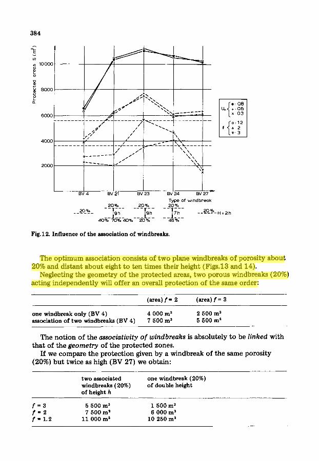
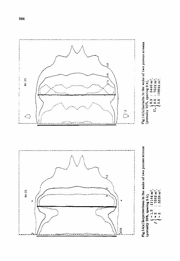
The optimum association consists of two plane windbreaks of porosity about 20% and distant about eight to ten times their height (Figs.13 and 14).
Neglecting the geometry of the protected areas, two porous windbreaks (20%) acting independently will offer an overall protection of the same order:
(area) f = 2 (area) f = 3
one windbreak o n l y ( B V 4) 4 0 0 0 m 2 2 5 0 0 m 2 assoc ia t ion o f t w o windbreaks ( B V 4) 7 5 0 0 m= 5 5 0 0 m 2
The notion of the associativity of windbreaks is absolutely to be linked with that of the geometry of the protected zones.
If we compare the protection given by a windbreak of the same porosity (20%) but twice as high (BV 27) we obtain:
two associated windbreaks (20%) of height h
one windbreak ( 2 0 % )
o f d o u b l e he ight
f = 3 5 5 0 0 m ~ 1 5 0 0 m 2 f = 2 7 5 0 0 m= 6 0 0 0 m 2 f = 1 .2 11 0 0 0 m= 1 0 2 5 0 m ~

385
T A B L E 2
C ombi~ t ionso fwindbr ea ks s tud i e d
windbreak number
BV 21
BV 23
BV 24
BV 27
BV 28
type of the f i r s t
w indbreak
I BV 4
BV 4
BV 4
BY 4 wi th height H = 2 h (~ 10 m)
BV 14
type of the second spacmg windbreak
~" (BV 10 ) ÷
L (BV 9) ÷
L(BV 10) = 120 m
9 h
BV 4 9 h
BY 10 7 h
corner aerodynamic
Lateral guiding f ins
-i Porous e lement (1 h upst ream)
Porous element (I h upstream 3 h downstream)
I ,// i / /
Fig.13. Association of windbreaks. Model in the wind tunnel.
3 8 6
t ,,,I
0
0
---.~
; \
\ /
/ i n
t
\
• / ( (" "D ' i . . . . . . . . . ° . - °
i i
s l ~ ',,x oo ,
0
0
0
o~
0
i
,,,~1~ ¢q ~
°~ . . . .
n n Ii
387
The associativity appears particularly interesting, in particular for the zones of greater comfort . Moreover, if the economic aspect of the construction is considered, it may be thought that the cost of two windbreaks of moderate height (3 to 4 m) will be less than that of one windbreak of twice the height.
In consequence, the association of two windbreaks appears to be an interest- ing avenue to pursue further (programme 78) since we wish to control both the geometry of the protected zones and the corresponding comfort level.
Remark: The influence of flexibility
In parallel with the wind tunnel investigations, full-scale measurements have been made on the near wake of vegetal hedges of different densities and flexi- bilities. The essential aim was to quantify (spectral analysis) the influence; of the inherent flexibility of the vegetation on the characteristics of the wake. All the types of hedge tested have shown the same tendency:
Reduction of the mean speed levels (about 50% in our examples, and behind the windbreak at three times the height of the hedge) a phenomenon which can to a great extent be at tr ibuted to the porosity of the screen.
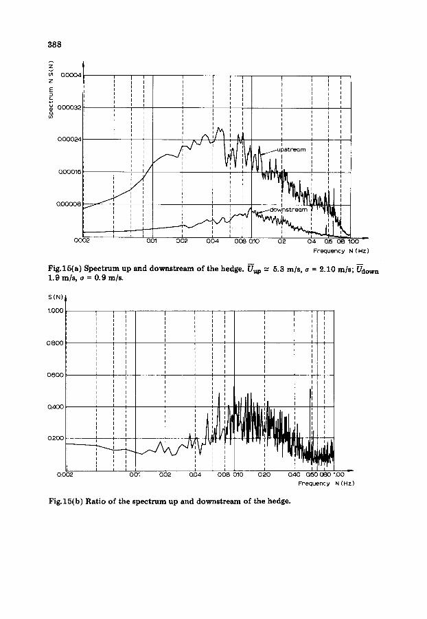
Practically uniform damping of the different fluctuations in the continuous range up to 10 Hz (total turbulence level reduced by half) (Fig.15(a)).
No preferred frequency peculiar to the vegetation appears in the spectrum. The square of the modulus of the transfer function (here, the ratio of the up- stream and downstream spectra, Fig.15(b)) shows a slight permeability at frequencies between 0.04 and 0.4 Hz.
If this spectral analysis is compared with the case of a rigid plane porous windbreak such that the level of mean speed and turbulence are both reduced roughly by 50%, we observe, both on the spectrum and on the transfer function, exactly the same phenomenon and the same levels.
In consequence, the behaviour of these two windbreaks (vegetal, porous screen) seems as a first approximation to be the same where their function of "fi l tering" a fluctuation that affects the comfort of a pedestrian is concerned. Hence, the results would tend to show that the flexibility parameter (of the hedges) does not play a part or else that our choice of samples, although realis- tic, was centred on hedges that were too rigid.
These tendencies make necessary a further experimental development (full scale and wind tunnel).
The point of view developed above does not, however, condemn the known efficiency of the porous vegetal screen (influence of porosity) which, for aesthetic or ecological reasons, can largely replace the "concre te" screen, even when of the best aerodynamic quality.
0 0 0 0 1 8
t z~ 0.0004
~, o.ooo32 r,
0 . 0 0 0 2 4
i ; , / ! i /
, I f 0.00008
i i
I
u
I I
I i
I i I I i I i I I t I I I
I I I
II i I I
I
i j I i I
388
I
i i
u p s t r e G m
i, W V l v 3 M ~ I
" " ' v , ~ , ~ . ,, ,",~
I I J I I Q O 0 2 0 0 1 Q 0 2 Q 0 4 0 2 0 . 1 0 0 . 2 0 . 4 Q 6 0 8 1 . 0 0 L
F r e q u e n c y N ( H z )
Fig.15(a) Spectrum up and downstream of the hedge. Uup = 5.3 m/s, e = 2.10 m/s; Udown 1.9 m/s, a = 0.9 m/s.
S ( N ) ,
1 . 0 0 0
0.800
0.600
0 . 4 0 0
0.200
0.002
i I I I I , I ' I I i
I I ' , i I I I I i I I i I I I I I ! I
q I I
L I i i I I I i i I I I I I I I I I I I I q I I I I i L n I I I i i
i I l I I I 1 I I I I I i I A L
I I I I I
n I I I I I
001 002 i 0.04
v!,
i
' I i i I t I I
' ' I I I I I I I i I I
I ~ I I I a ] I I I I I I I
I I I I I
: I I I I I I I I I I I I I I
I
i i l . J I I ' ,I ', l[ ',
J fl'lll ,llUJ, ,"
I I [ ? i 0 0 8 0 1 0 0 2 0 Q 4 0 Q ~ ~ 1 1 0 0
F r e q u e n c y N ( H z )
Fig.15(b) Ratio of the spectrum up and downstream of the hedge.
389
Future programme
Our work has shown the interest there is in controlling the aerodynamic parameters of windbreak screens if one wishes to obtain the opt imum protect ion (both in terms of comfor t level and of area size in their wake). At the end of this first phase, a certain number of results are available, in particular in relation to porous windbreaks.
It now remains for us to s tudy certain treatments more deeply, for example the aerodynamic end effects, the associativity of several windbreaks, or again, the efficiency of different species of shrubs on comfort .
In addition, our next investigations aim at quantifying the effective protec- tion of winbreak structures in their context of use: the influence of the nature of the wind (country or suburban type} and of its incidence, the influence of the near environment (practical cases}, and that in association with the actual dimensions of the windbreak.
References
1 J. Gandemer, Etude du contrSle local du vent: a~rodynamique des brise-vent, EN ADYM 77.9.L, C.S.T.B. Nantes.
2 J. Gandemer and A. Guyot, Integration du ph~nom~ne vent dans la conception du milieu, biti, Publication Groupe Central des Villes Noucelles, Secretariat des Villes Nouvelles, 1977.
3 J.K. Raine and D.C. Stevenson, Wind protection by model fences in a simulated atmo- spheric boundary layer, J. Industrial Aerodynamics, 2 (1977 ) 159.
4 G. Guyot, Etude de l'~coulement de Fair au voisinage d'un obstacle poreux en couche limite turbulente, Th~se de Docteur Ing~nieur, Universit~ Paris VI, 1972.