journal of petroleum science and engineeringicheh.com/files/posts/portal1/ (1)_1.pdf · a...
TRANSCRIPT

Journal of Petroleum Science and Engineering 66 (2009) 98–110
Contents lists available at ScienceDirect
Journal of Petroleum Science and Engineering
j ourna l homepage: www.e lsev ie r.com/ locate /pet ro l
A generalized correlation for predicting gas–condensate relative permeability at nearwellbore conditions
M. Jamiolahmady ⁎, M. Sohrabi, S. Ireland, P. GhahriInstitute of Petroleum Engineering, Heriot-Watt University, Riccarton, Edinburgh EH14 4AS, UK
⁎ Corresponding author. Tel.: +44 131 4513122; fax:E-mail addresses: [email protected] (M. Ja
[email protected] (M. Sohrabi), mehran.sora
0920-4105/$ – see front matter © 2009 Elsevier B.V. Adoi:10.1016/j.petrol.2009.02.001
a b s t r a c t
a r t i c l e i n f oArticle history:
It is a well established findi Received 20 December 2006Accepted 2 February 2009Keywords:relative-permeabilitygas–condensatecoupling effectinertial effectfluid flowlow interfacial fluid tension systems
ng, both experimentally and theoretically that relative permeability (kr) of gas–condensate systems at low interfacial tension (IFT) depends on velocity and IFT. There are a number ofcorrelations available both in the literature and commercial reservoir simulators that account for the coupling(i.e., the increase of kr as velocity increases and/or IFT decreases) and inertial (i.e., the reduction of kr as velocityincreases) effects at nearwellbore conditions. These functional forms, whichwith the exception ofWhitson et al.(Whitson, C.H., Fevang, O., Saevareid, A., Oct.1999. Gas condensate relative permeability forwell calculations, SPE56476. Proc. of SPE Annual Technical Conference and Exhibition Texas) are based on saturation, estimate the twoeffects separately and include a number of parameters, which should be determined by cumbersome andexpensive kr measurements at low IFT and high velocity conditions. We have previously reported thedevelopment of a fractional flow based correlation (Jamiolahmady, M., Danesh, A., Henderson, G.D. and Tehrani,D.H., Dec. 2006. Variations of gas–condensate relative permeability with production rate at near wellboreconditions: a general correlation, SPE Reserv. Eng. Evalu. J., 9 (6), pp. 688–697), which expressed the combinedeffect of coupling and inertia simultaneously, but its dependency on fluid viscosity limited its use to the range ofIFT values studied. In this paper we present a generalized correlation based on relative-permeability-ratio, whichis closely related to a fractional flow of gas and condensate. The parameters of the new correlation are eitheruniversal, applicable to all types of rocks, or can bedetermined from commonlymeasuredpetrophysical data. Theperformance of the correlation has been evaluated over a relatively wide range of IFT and velocity variations. Thishas been conducted by comparing its predictionwith the gas–condensate relative permeability values measuredon porous media with very different characteristics. These data had not been used in developing the correlation.The results are quite satisfactory confirming the generality of the correlation in providing reliable information ongas–condensate relative permeability values for near wellbore conditions.
© 2009 Elsevier B.V. All rights reserved.
1. Introduction
The characteristics of gas and condensate flow, when pressure fallsbelow dew point, are significantly different from those of conventionalgas–oil systems and accurate determination of gas–condensate relativepermeability (kr) values, is amajor challenge (Jamiolahmady et al., 2000).
The effect of interfacial tension (IFT) on relative permeability at lowIFT values has been known for a considerable time (e.g., Bardon andLongeron, 1980; Asar and Handy, 1988). The improvement to therelative permeability of condensing systems due to an increase invelocity is also a relatively well established experimental finding (e.g.,Danesh et. al., 1994; Henderson et al., 1997, 2001; Ali et al., 1997; Blomet al., 1997). This improvement in relative permeability of low IFTsystems as velocity increases and/or IFT decreases, known as thecoupling effect, has been attributed to the simultaneous coupled flow
+44 131 4513127.miolahmady),[email protected] (P. Ghahri).
ll rights reserved.
of the gas and condensate phases with the intermittent opening andclosure of the gas passage by the condensate at the pore level(Jamiolahmady et al., 2000, 2003). This cyclic two-phase flow pattern,unique to gas condensate systems, was observed in the micromodelexperiments conducted by authors ((Jamiolahmady et al., 2000). Thedeveloped single pore mechanistic model capturing the competitionbetween viscous and capillary forces, consistentwith the experiments,showed that for these low IFT systems, there is a highly conductive filmof condensate flowingwith the gas. The condensate evolves at the porethroat and blocks the gas passage, afterwhich the flowof gas continuestill it overcomes the capillary barrier. As IFT increases the number ofpores promoting this flow pattern gradually diminishes switching to aconventional Darcy type of flow mechanism used in the channel flowconcept. Hence, when the effect of multiple pore interaction wasincluded in a network of pores (Jamiolahmady et al., 2003) kr valuescomparable with experimentally measured values were reported.
There are now several correlations in the literature (e.g., Hendersonet al.,1996;BlomandHagoort,1998; Popeet al.,1998;Whitsonet al.,1998)and in commercial reservoir simulators (e.g., ECLIPSE, VIP) to express the

Nomenclature
Aj Parameter, j=1 to 7Cj Constant, j=1 to 15k Absolute permeability, m2 or mDk(Swi) Permeability at Swi, m2 or mDke Effective permeability, m2 or mDkr Relative permeability, dimensionlesskrgtr Relative permeability ratio, i.e., krg/(krg+ krc),
dimensionless(krgtr)Micpoeff krgtr value at which krg affected by the
presence of micro-pores, dimensionlessL Length, mP Pressure, Pa or psiaQ Flow rate, m3 s−1
Swi Immobile water saturation, dimensionlessSw1 μm Wetting phase (air) saturation corresponding to one
micron radius from mercury porosimetry Pc curve,dimensionless
u Darcy velocity, m s−1
Yg Gas weight function for interpolation of kr, dimensionless(Yg)Main Gas weight function for majority of data points fol-
lowing main trend, dimensionless(Yg)Micpoeff Gasweight function fordatapoints not following
main trend due to effect of micro-pores, dimensionless
Greek lettersβ Single-phase inertial factor, m−1
β(Swi) Single-phase inertial factor at Swi, m−1
βg Two-phase inertial factor for gas phase, m−1
ϕ Porosity of porous medium, %μ Viscosity, kg (ms)−1or cpρ Density, kg m−3
σ Interfacial tension, IFT, between gas and liquid, N m−1
or mN m−1
σr Ratio of the base IFT of 3.0 mN m−1 to current IFT,dimensionless
Subscriptave Average value of the quantityb Value of the quantity for the base case at highest
measured interfacial tension, IFT=3 mN m−1, andlowest velocity
g Gas phaseiner Value of the quantity affected by inertiaj An indexc Condensatem Miscible caseT Total
Abbreviationsfg Gas to total flow rate ratioIFT Interfacial tensionNc′ Capillary number, ratio of viscous to capillary forcesNcr′ Ratio of current Nc′ to base Nc′
Operators| | Absolute valueΔ Difference operator▿· Divergence operator▿ Gradient operator
99M. Jamiolahmady et al. / Journal of Petroleum Science and Engineering 66 (2009) 98–110
capillary number (ratio of capillary to viscous forces) dependence of thetwo-phase flow of gas and condensate at these low IFT systems.
Henderson et al. (2001), through some steady-state kr measure-ments, reported that at low condensate saturations the relativepermeability values decreased when the flow rate was increased, dueto the dominance of the inertial effect. However, the positive couplingeffect surpassed the inertial effect at higher condensate saturationresulting in a net increase of relative permeability with velocity. Thereare some correlations to express the effect of inertia using a two-phaseinertial factor βg (e.g., Henderson et al., 2001; Whitson et al., 1999;Mott et al., 2000; App and Mohanty, 2002). The main difficulty inaccounting for the inertial effect in all the reported correlations is therequirement for estimating βg. Correlations have been reported in theliterature for calculating βg (e.g., Narayanaswamy et al., 1999; Dacun,and Thomas, 2000), which relate βg mainly to Sg and/or krg. However,the application of these correlations to gas–condensate systems isopen to question as they have been developed mainly for gas–watersystems, with the immobile water phase (Al-Kharusi, 2000).
We recently proposed a fractional flow based correlation (Jamiolah-mady et al., 2006) accounting for the combined effects of coupling andinertia as a function of fractional flow. The choice of fractional flowas themain independent variable rather than saturation was based on ourobservation that it could express relative permeability of core sampleswithdifferent characteristicsmore reliably. That is, different core sampleshave a different pore size distribution, which could lead to differentdistributions of the phases, i.e., different phase saturation, at similar flowconditions. Furthermore, fractional flow is directly related to fluidcomposition and pressure at steady-state conditions, which is generallyprevailing near the wellbore, hence, it makes it practically much moreattractive compared to that of saturation which depends on corecharacteristics. The condensate relative permeability is also linked tothat of gas by the fractional flow, thereby eliminating the need for aseparate correlation for its calculation. However, the dependency ofrelative permeability to fluid viscosity and the lack of a proper definitionof the lower limit of the correlation limited its use to the range of IFTvalues studied. In other words, as will be discussed in Section 2.3, thereported base IFTof 0.85mNm−1, abovewhich kr is not a function of IFT,is not a universal value and the threshold capillary number fixing thelower limit of velocity (below which kr is not a function of velocity) hasalso not been identified. It will be demonstrated that although fractionalflow and relative permeability ratio are closely related, the inclusion ofviscosity in the definition of independent variablemakes it difficult to fixthe base conditions. In other words, the base kr curve reported as afunction of fractional flow rate makes it fluid dependent whilst its effectcan easily be accounted for separately when calculating the relativepermeability ratio from the known fractional flow and viscosity valuesfacilitating its generality. This together with the lack of proper definitionfor base capillary number, as will be demonstrated in Section 3, couldresult in a highly erroneous estimation of relative permeability iffractional flow based correlation is used. In this manuscript we haveremoved both these limitations and sought simpler mathematicalexpressions. This enables us to have a correlation with either universalparameters, applicable to all types of rocks, or those that can be deter-mined from commonly measured petrophysical data.
2. Structure of correlation
In a two-phase flow systemDarcy's law, which was developed for asingle-phase flow, is used by replacing the absolute permeability (k)with the effective permeability (ke), which is reported as relativepermeability (kr=ke/k). In gas–condensate systems the relativepermeability could be affected by both the coupling (i.e., the increaseof kr as velocity increases and/or IFT decreases) and inertial (i.e., thereduction of kr as velocity increases) effects.
In the new proposed formulation, krg is interpolated between the base(krgb) and themiscible-fluids curves (krgm) using an interpolation function

100 M. Jamiolahmady et al. / Journal of Petroleum Science and Engineering 66 (2009) 98–110
Yg. This simple interpolation approach has been favoured by manyinvestigators to express the coupling effect on kr of gas–condensatesystems at different values of capillary number (e.g., Coats, 1980;Henderson et. al., 1996; Whitson et al., 1999). However, here, similarly tothe fractional flow based correlation (Jamiolahmady et al., 2006) wemodify both krgm and krb for the effect of inertia, which enables us toexpress the combined effect of coupling and inertia simultaneously, usingEq. (1).
krg = Yg krgb� �
iner+ 1− Yg� �
krgm� �
iner: ð1Þ
The complete list of variables can be found in the nomenclaturesection.
The main independent variable is the relative-permeability-ratiodefined as,
krgtr =krg
krg + krc=
1
1 + krckrg
� � : ð2Þ
Solving the above equation for condensate relative permeability,krc, gives:
krc =krg 1− krgtr� �krgtr
: ð3Þ
Therefore, when krg is determined as a function of krgtr thisequation automatically gives the corresponding value of krc for thesame value of krgtr.
krgtr ratio could be calculated in terms of gas fractional flow (fg),and fluid viscosities. That is, fg is defined as,
fg =Qg
Qg + Qc=
ug
ug + uc=
krμ
h ikrμ
h ic+ kr
μ
h ig
; ð4Þ
where Q is the volumetric flow rate, u is the Darcy velocity, μ is theviscosity and subscripts (g) and (c) refers to the gas and condensatephases, respectively.
The extended form of Darcy's law for two-phase flow, Eq. (5), hasbeen used in Eq. (4) to relate velocity to relative permeability as,
u=kkrjP
μ
� �j
j = g; c; ð5Þ
where P is the pressure, k is the absolute permeability and ▿ is thegradient operator.
Solving Eq. (4) for relative-permeability-ratio gives:
krckrg
!=
1− fg� �
fg
μc
μg
!: ð6Þ
Substituting Eq. (6) into Eq. (4), after some mathematicalmanipulation, krgtr can be related to fg by,
krgtr =krg
krc + krg=
μgfg
μgfg + μc 1− fg� � : ð7Þ
The use of relative-permeability-ratio based on the summation ofrelative permeability values of gas and condensate in the denominator ofEq. (7), rather than the relative permeability of one of the two phases(e.g., krgcr, which is the gas to condensate relative permeability ratio)avoids themathematical difficulty associatedwith the latter (i.e.,krgcr→∞when krc→0 which is equivalent to condensate flow rate→0).
2.1. Miscible-fluids relative permeability for gas (krgm)
In the present krgtr based correlation the gas miscible curve ismodified to include the inertial effect with an argument similar to that
presented for the fractional flow based correlation (Jamiolahmadyet al., 2006). This is due to the fact that the formulation for the fg-basedcorrelationwas obtained bymomentum balance, which is not going tobe affected by the choice of variable. Therefore, for fg we can write
krgm� �
iner=
krgtr
1 + βρmkμm
� �ju j sm
0@
1A; ð8Þ
where | | refers to the absolute value of the quantity, β is the (single-phase) Forchheimer coefficient sometimes referred to as the non-Darcy or inertial coefficient and subscriptm refers to themiscible case.
In Eq. (8) the required miscible fluid properties (i.e. density, ρm,and viscosity, μm) are the arithmetic average of the fluid properties ofgas and liquid at any given pressure (in the vicinity of the dew point),which is a good approximation of the average values at the dew pointthat are not easily available.
2.2. Base relative permeability for gas (krgb)
The base relative permeability curve is the measured curve at thelowest velocity level (above which kr is a function of velocity) and thehighest IFT value (below which kr is a function of IFT), (krgb)meas,which is then modified for the effect of inertia, (krgb)iner when thevelocity is high. The exact definition of (krgb)meas will be discussedlater in this section. Here a similar approach to that used for themiscible curve was adopted, i.e., defining an equivalent single phase,eliminating the need for the two-phase Forchheimer factor, βg. Inother words, the inertial pressure drop was calculated by using thesingle-phase inertial factor, β, the total velocity, uT, and the summationof total momentum inflow of gas and condensate. Therefore, krgb thatis modified for the effect of inertia is calculated by
krgb� �
iner=
krgb� �
meas
1 +βρavek krgbð Þmeas
fgμgju jT
0B@
1CA: ð9Þ
In Eq. (9), the weighted average density value is calculated at thebase conditions and based on the fractional flow of the two flowingphases. Eqs. (8) and (9) correctly extend the correlation to the single-phase flow limits. That is, if (krgm)iner from Eq. (8) or (krgb)iner from Eq.(9) is substituted in Darcy law, Eq. (5), and re-arranged it gives theForchheimer Equation (1914):
jP =μku + βρ ju ju
h ig
ð10Þ
Due to the presence of the rock properties (k and β) in Eqs. (8) and(9), there are miscible and base relative permeability versus krgtr curvesfor each core at any velocity value. The base and miscible gas relativepermeability curves calculated using Eqs. (8) and (9) for Clashach andTexas Cream cores at different velocities are shown in Fig. 1a and b,respectively. It is noted that the gas miscible curve defined by Eq. (8), atlow velocities where the inertial term is insignificant, will approach thekrg=krgtr linebut athigh velocities the slope of the linedeviates from45°to lower values depending on the values of velocity and single-phaseinertial factor for the given fluid system. Similarly, the base relativepermeability curve at low velocities is close to the correspondingmeasured value but athigh velocities it is reduced. This reduction ismorepronounced, at higher krgtr values (higher gas fractional flow rates).
Eqs. (9) and (10) are also valid for SwiN0, with keg(Swi) and βg(Swi)replacing k and β, respectively, assuming that immobile water actslike a part of the rock.
2.3. Measured base relative permeability for gas (krgb)meas
The base-relative-permeability curve in our previous work(Jamiolahmady et al., 2006) was given at IFT=0.85 mN m−1, with

Fig. 1. Base and miscible gas relative permeability versus relative-permeability ratio at three different velocities calculated using Eqs. (8) and (9), respectively, for a) Clashach coreb) Texas Cream core.
101M. Jamiolahmady et al. / Journal of Petroleum Science and Engineering 66 (2009) 98–110
the recommendation for field application that the base curve shouldbe measured at the highest applicable value of IFT for the fluid underconsideration and the lowest practicable velocity. A series of relativepermeability measurements were made on a Texas Cream limestonecore at IFT values higher than 0.85, as shown in Fig. 2. The objectivewas to investigate the effect of increasing IFT on the gas andcondensate relative permeability and to identify the IFT value abovewhich the relative permeability would not be affected by velocity.
The results indicated that there was a continual reduction in relativepermeability with increasing IFT if kr was expressed in terms of fractionalflow rate ratio (fg), Fig. 2a. However, if the relative permeability curveswere plotted versus relative permeability ratio, the effect of viscosity,fluidproperty, was eliminated and the variation of kr curves measured at highIFTwas demonstrated to beminimal, Fig. 2b. These experimentalfindingssuggested that the IFTvalueof 0.85mNm−1 considered for thebase curvein the previous study is not a universal value and it could have a value inthe range of 1 to 3 mN m−1, Fig. 2b. The two figures also show that at agiven value of IFT the low velocities in the range of 5 to 50 m d−1 have aminimal effect on relative permeability, especially at high values of fg. InFig. 2b it canbenoticed that there is a slight decrease in (krgb)meas,which ismore pronounced at higher krgtr values, when IFT increases from 0.85 to3 mN m−1. These results highlight that the effect of reduction of IFT cannot be compensated by an equivalent increase in velocity. Later in thefollowing section it will be shown that the effect of viscous and capillaryforces are independently accounted for using a combination of IFT andcapillarynumber (ratio of viscous to capillary forces).Hence, bothbase IFT
and base capillary number are required for this correlation, which hasuniversal parameters. After careful examination of the measured data,accuracy of themeasurements and the fact that at higher IFT values and/or lower velocities the coupling effect is diminishing for all core types, weselected a base IFT and capillary number of 3 mN m−1 and 1E−7,respectively, for measuring the base relative permeability. This value forthe base capillary number was obtained using Eq. (11) as follows:
Nc =μg ug + uc
� �σ
; ð11Þ
where σ is the interfacial tension.Based on the data of Fig. 2 for core samples with measurements at
IFT of 0.85 mN m−1 rather than base IFT of 3 mN m−1, Eq. (12) wasused to adjust the base curve data.
krg� �
meas
h iIFT=3
krg� �
meas
h iIFT=0:85
= 0:69 + 0:31 krgtrh i7:07 ð12Þ
2.4. Weight function formulation (Yg)
To determine the form of the weight function Yg, Eq. (1), we usedexperimentally measured krg values on selected Clashach, Berea, TexasCream and RC2 core samples. Tables 1–4 include the basic data for the

Fig. 2. Gas relative permeability at two velocities and three IFT values for Texas Cream core sample based on (a) gas to total fractional flow rate ratio (b) gas to total, gas pluscondensate, relative permeability ratio.
102 M. Jamiolahmady et al. / Journal of Petroleum Science and Engineering 66 (2009) 98–110
different sets of measurements conducted on these core samplesincluding the range of IFT and velocity values at which the relativepermeability measurements were conducted. This comprehensive databank included over 1300 relative permeability measurements. Anumber of measurements on a number of core samples, i.e., Clashach,Texas Cream, RC3 and a propped fracture, Table 5, were excluded so that
Table 1Basic test data for experiments conducted on Clashach core at different conditions.
Index Swi k k(Swi) IFT β β(Swi) Velocityrange
(krgtr)Micpoeffa
(%) (mD) (mD) (mNm−1) (m−1) (m−1)
1 0 553 – 0.85 1.035E8 – 7.3–700 –
2 0 553 – 0.15 1.035E8 – 7.3–700 0.9893 0 553 – 0.036 1.035E8 – 7.3–350 0.9924 0 600 – 0.15 5.990E7 – 7.1–699 –
5 0 600 – 0.036 5.990E7 – 7.1–699 –
6 33 553 245 0.85 1.035E8 4.580E8 10.9–1044 –
7 21 553 446 0.85 1.035E8 1.395E8b 9.2–885 –
8 21 553 446 0.15 1.035E8 1.395E8b 9.2–738 –
9 15 440 400 0.85 1.035E8 1.151E8b 9.4–74.9 –
10 15 440 400 0.15 1.035E8 1.151E8b 9.4–74.9 –
Swi is the amount of immobile water saturation and k(Swi) and β(Swi) are the single-phase permeability and inertia factor, respectively, of the core sample at Swi.IFT refers to interfacial tension.
a (krgtr)Micpoeff refers to krgtr=krg/(krg+krc) value at which the measured krg hasbeen affected by the presence of micro-pores.
b Calculated β(Swi) value using, Eq. (17) of Jamiolahmady et al., (2006).
the evaluation exercise conducted on the performance of the correlationincluded data that were not used for its development. This data bankincluded over 200 additional relative permeability measurements.
To determine the functional form of Yg, for each krg measuredexperimentally at the prevailing conditions, Yg was calculated, usingthe following equation:
Yg =krg − krgm
� �iner
krgb� �
iner− krgm� �
iner
; ð13Þ
which is the re-arranged form of Eq. (1). (krgm)iner at any velocitylevel and krgtr were calculated using Eq. (8) and (krgb)iner was the
Table 2Basic test data for the experiments conducted on Berea core at different conditions.
Index Swi k k(Swi) IFT β β(Swi) Velocityrange
(krgtr)Micpoeff
(%) (mD) (mD) (mN m−1) (m−1) (m−1)
11 0 110 – 0.85 1.870E8 – 7.1–454 –
12 0 110 – 0.15 1.870E8 – 7.1–567 0.989, 0.97813 0 110 – 0.036 1.870E8 – 7.1–227 0.985, 0.954,
0.92514 26 110 92 0.85 1.870E8 2.286E8a 9.2–73.7 –
15 26 110 92 0.45 1.870E8 2.286E8a 9.2–73.7 –
16 26 110 92 0.15 1.870E8 2.286E8a 9.2–73.7 –
17 26 110 92 0.036 1.870E8 2.286E8a 9.2–73.7 –
a Calculated β(Swi) value using, Eq. (17) of Jamiolahmady et al., (2006).

Table 3Basic test data for experiments conducted on Texas Cream at different conditions.
Index Swi k k(Swi) IFT β β(Swi) Velocityrange(%) (mD) (mD) (mN m−1) (m−1) (m−1)
18 0 9.1 – 0.85 3.927E9 – 6.0–28619 0 11.1 – 0.15 3.927E9a – 5.6–44.620 22 11.1 8.4 0.15 3.927E9a 5.933E9b 7.2–57.221 22 11.1 8.4 0.036 3.927E9a 5.933E9b 7.2–57.2
a β of Texas Cream with k=9.1 mD, has been used due to lack of β measurement.b Calculated β(Swi) value using, Eq. (17) of Jamiolahmady et al., (2006).
Table 4Basic test data for experiments conducted on RC2 at different conditions.
Index Swi k k(Swi) IFT β β(Swi) Velocityrange(%) (mD) (mD) (mN m−1) (m−1) (m−1)
22 0 11 – 0.85 1.623E10 – 3.4–43023 0 11 – 0.15 1.623E10 – 6.7–21524 0 11 – 0.036 1.623E10 – 6.7–10825 33 11 7.9 0.85 1.623E10 2.527E10a 10.0–32126 33 11 7.9 0.15 1.623E10 2.527E10a 10.0–16127 33 11 7.9 0.036 1.623E10 2.527E10Ma 10.0–80.3
a Calculated β(Swi) value using, Eq. (17) of Jamiolahmady et al., (2006).
Table 5Basic test data for experiments conducted on a number of cores at different conditions.
Index Core type Swi k k(Swi) IFT β or β(Swi) Velocityrange(%) (mD) (mD) (mN m−1) (m−1)
28 Clashach 0 140 – 0.85 7.035E8 8.0–77029 25 140 100 0.85 1.164E8a 10.7–102730 Texas Cream 0 7.4 – 0.85 3.927E9b 6.1–48.931 25 7.4 5.6 0.85 6.498E9a 8.2–65.232 RC3 0 3.9 – 0.85 1.550E11 22.8–18333 0 3.9 – 0.15 1.550E11 22.8–18334 0 3.9 – 0.036 1.550E11 2.3–91.335 Propped fracture 0 146,000 – 0.85 3.511E5 250–1500
a Calculated β(Swi) value using, Eq. (17) of Jamiolahmady et al., (2006).b β of Texas Cream with k=9.1 mD, has been used due to lack of β measurement.
103M. Jamiolahmady et al. / Journal of Petroleum Science and Engineering 66 (2009) 98–110
experimentally measured base krg value at any given krgtr modified forthe effect of inertia using Eq. (9).
The Yg weight function depends on the capillary number ratio, theratio of the prevailing capillary number to its base value. Similarly tothe fractional flow based correlation (Jamiolahmady et al., 2006) thecapillary number defined by Eq. (14) was selected to represent the
Fig. 3. Yg vs. Ncr′ for differe
ratio of viscous and capillary forces, which proved to correlate the datamore consistently.
Nc′ =kΔP/σL
=k jjP j/σ
; ð14Þ
where ϕ is the porosity and L is the core length.It is noted that the capillary number expression, in Eq. (14), is
different from that of Eq. (11) used for defining the base capillarynumber. However, as it will be discussed later they are related to oneanother using Darcy law for two-phase flow, Eq. (5).
The data of Fig. 3 is the plot of calculated Yg based on theexperimentally measured relative permeability on two dry (withoutinitial water saturation) Clashach core samples at different IFT valuesbased on krgtr. The data in this figure demonstrate that the bulk of datafollows a consistent trend but very scattered. In this figure a group ofdata have been marked ‘deviating data' with low Yg values thatcorrespond to data points at low IFT and high krgtr values, Fig. 3. Thisdifferent behaviour is attributed to the contribution of a different flowmechanism because of to the presence of condensate in the micro-pores of the core at high krgtr values (high gas fractional flow rates).Micro-pores have been shown to affect the flow behaviour ofconventional gas–oil systems. Mcdougall et. al. (2002) had to usetwo different pore size distributions to match the Pc curves of coreswith micro-pores. It was noted that for deviating data of Fig. 3, the(krgb)meas values are much lower than their corresponding krg valuesat the same krgtr but at lower IFT values, Fig. 4. That is, in the presenceof these micro-pores at lower IFT values, condensate flow does notimpede the flow of gas, i.e., krg is close to unity. But at higher base IFTvalue the condensate flow restricts the flowof gas thereby reducing itskr to very low values, which results in very low Yg values, Eq. (12). Ifthe percentage of these small pores is very high, e.g., Texas Cream,even at base IFT, the flow of gas is not affected by the flow ofcondensate and the (krgb)meas values are close to unity and to thecorresponding values at lower IFT for the same high krgtr, Fig. 5, henceYg will not take these low values. Furthermore, it is noted that in thelatter case because of to the small difference between the twointerpolation limits, i.e. (krgb)meas and krgm the accuracy of the weightfunction, Yg, does not affect the interpolated value, krg, significantly.
For the Clashach and Berea core samples the limit of this effect isdifferent. Last columns in Tables 1 and 2 include the correspondingkrgtr values for these data points. These data indicate that for theClashach core, where there is a very small percentage of the micro-pores, the contribution is limited to very high krgtr values, Table 1,
nt Clashach core tests.
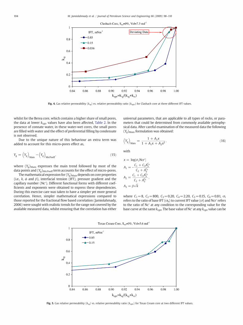
Fig. 4. Gas relative permeability (krg) vs. relative permeability ratio (krgtr) for Clashach core at three different IFT values.
104 M. Jamiolahmady et al. / Journal of Petroleum Science and Engineering 66 (2009) 98–110
whilst for the Berea core, which contains a higher share of small pores,the data at lower krgtr values have also been affected, Table 2. In thepresence of connate water, in these water-wet cores, the small poresare filled withwater and the effect of preferential filling by condensateis not observed.
Due to the unique nature of this behaviour an extra term wasadded to account for this micro-pores effect as,
Yg = Yg� �
Main− Yg� �
MicPoeff; ð15Þ
where (Yg)Main expresses the main trend followed by most of thedata points and (Yg)MicPoeff term accounts for the effect of micro-pores.
Themathematical expression for (Yg)Main depends on coreproperties(i.e., k, ϕ and β), interfacial tension (IFT), pressure gradient and thecapillary number (Nc′). Different functional forms with different coef-ficients and exponents were obtained to express these dependencies.During this exercise care was taken to have a simpler yet more generalcorrelation. Hence, simpler mathematical expressions compared tothose reported for the fractional flow based correlation (Jamiolahmady,2006)were soughtwith realistic trends for the range not covered by theavailable measured data, whilst ensuring that the correlation has either
Fig. 5. Gas relative permeability (krg) vs. relative permeability r
universal parameters, that are applicable to all types of rocks, or para-meters that could be determined from commonly available petrophy-sical data. After careful examination of the measured data the following(Yg)Main formulation was obtained:
Yg� �
Main=
1 + A1x1 + A1x + A2x
2 ; ð16Þ
with
x = log σ rNcr′½ �
A1 = –C1 + C3A
C43
C2 + AC43
A2 =C1 + C5A
C63
C2 + AC63
;
A3 = βffiffiffik
p
where C1=8, C2=800, C3=0.20, C4=2.20, C5=0.15, C6=0.81, σr
refers to the ratio of base IFT (σb) to current IFT value (σ) and Ncr′ refersto the ratio of Nc′ at any condition to the corresponding value for thebase curve at the samekrgtr. The base value of Nc′ at any krgtr value can be
atio (krgtr) for Texas Cream core at two different IFT values.

Fig. 6. (Yg)Main vs. σrNcr′ product for Berea core tests together with best fitted curve, Eq. (16).
Fig. 7. (Yg)Mipoeff vs. σrNcr′ product for data of Clashach and Berea core tests at high krgtr affected by micro-pores together with the best fitted curve, Eq. (18).
Table 6The percentage of micro-pores in the cores reflected by Sw1 μm.
Core type k ϕ Sw1 μm
(mD) (%) (PV)
Clashach 553 17.8 0.032Clashach 140 16.0 0.050Berea 110 18.2 0.232Texas Cream 11.1 23.3 0.430Texas Cream 7.4 21.0 0.430a
RC2 11 18.0 0.296RC3 3.9 6.0 0.191Propped fracture 146,000 35.4 0.001
k is the absolute permeability, ϕ is the porosity, Sw1 μm is the wetting phase saturation atcapillary pressure corresponding to the radius value of one micrometer obtained frommercury porosimetry Pc curve.
a Sw1 μm of Texas Creamwith k=11 mD, has been used due to lack of Pc measurement.
105M. Jamiolahmady et al. / Journal of Petroleum Science and Engineering 66 (2009) 98–110
obtained by Eq. (17), which requires the measured krgb, fluid propertiesand the corresponding base Nc of 1E−7 defined earlier,
Ncb′ =fg
/ krgb� �
meas
Ncb =fg
/ krgb� �
meas
1E − 7; ð17Þ
Eq. (17) has been obtained using Darcy law for two-phase flow,Eq. (5), and Eq. (11). Furthermore, for both the base Ncb′ and (krgb)meas,Hermite cubic spline interpolation method is used to cover the wholerange of krgtr variation.
Fig. 6 is the plot ofYg calculated frommeasured krg data using Eq. (13)for Berea together with the best fitted curve calculated using Eq. (16).
Fig. 7 demonstrates that for the measurements affected by micro-pores, the difference between Yg calculated from measured krg datausing Eq. (13) and the corresponding (Yg)Main values obtained fromEq. (16), can be expressed by a mathematical expression as,
Yg
� �MicPoeff
=1 + C7x
1 + C7x + C8x2
� �A4A5; ð18Þ
where x=log[σrNcr′], C7=−0.11, C8=0.03.In Eq. (18), A4 and A5 terms determine the limit and extent of
(Yg)MicPoeff and are function of krgtr, IFT and the percentage of micro-poresin the core. Different options were considered to reflect the amount of
micro-pores in the system. Finally, considering the reliability and theamount of information available, Sw1μm, which is the wetting phasesaturation at capillary pressure (Pc) corresponding to the radius value ofone micrometer obtained from mercury porosimetry Pc curve, wasselected. The irreducible water saturation in the cores would fill themicro-pores and hence, the flow of gas and condensate would not beaffected by these pores for the corresponding measurements for cores

Table 7Average absolute deviations (AAD) and standard error of estimates (SEE) betweenmeasured and calculated values of krg for Clashach core at different conditions.
Index Swi IFT AAD%-krg SEE-krg AAD%-krg SEE-krg
(%) (mN m−1) (1) (1) (2) (2)
1 0 0.85 14.6 0.043 14.6 0.0432 0 0.15 19.9 0.144 12.7 0.0513 0 0.036 13.4 0.090 11.2 0.0624 0 0.15 23.0 0.084 23.0 0.0845 0 0.036 16.3 0.085 16.3 0.085Ave. 17.4 0.091 15.6 0.0656 33 0.85 20.0 0.042 20.0 0.0427 21 0.85 20.7 0.048 20.7 0.0488 21 0.15 34.9 0.237 34.9 0.237Ave. 27.8 0.165 27.8 0.1659 15 0.85 11.6 0.022 11.6 0.02210 15 0.15 14.4 0.036 14.4 0.036Ave. 13.0 0.031 13.0 0.031All 18.9 0.105 17.9 0.093
AAD% and SEE refer to average absolute percentage deviation and standard error ofestimates, respectively.(1) Corresponds to krg values obtained using (Yg)Main, Eq. (16).(2) Corresponds to krg values obtained using Yg, Eq. (15).
Table 9Average absolute deviations (AAD) and standard error of estimates (SEE) betweenmeasured and calculated values of krg for Texas Cream core at different conditions.
Index Swi IFT AAD%-krg SEE-krg
(%) (mN m−1) (2) (2)
18 0 0.85 8.7 0.04519 0 0.15 11.2 0.063Ave. 10.0 0.05220 22 0.15 18.2 0.07521 22 0.036 6.2 0.049Ave. 12.2 0.064All 11.1 0.056
Table 10Average absolute deviations (AAD) and standard error of estimates (SEE) betweenmeasured and calculated values of krg for RC2 reservoir core at different conditions.
Index Swi IFT AAD%-krg SEE-krg
(%) (mN m−1) (2) (2)
22 0 0.85 17.5 0.04923 0 0.15 14.3 0.07924 0 0.036 11.8 0.097Ave. 14.5 0.07325 33 0.85 21.4 0.06026 33 0.15 12.8 0.07927 33 0.036 7.7 0.081Ave. 14.0 0.072All 14.3 0.072
106 M. Jamiolahmady et al. / Journal of Petroleum Science and Engineering 66 (2009) 98–110
with SwiN0 provided that SwiNSw1μm, which was the case for all mea-surements conducted here.
In Eq. (18), A4 limits the effect of micro-porosity to the correspon-ding krgtr and IFT values for the cores with low and moderatepercentage of micro-pores (e.g., Clashach and Berea cores, Table 6) bythe following equation:
A4 =C29 + krgtr
h iA6
C9 + krgtrh iA6
264
375
A6 =A7C9 + C10 IFTr½ �C11
C9 + IFTr½ �C11
" #;
A7 =A9C10 + C12 Sw1μm
h iC13
C9 + Sw1μm
h iC13264
375
ð19Þ
where C9=1E−4, C10=1200, C11=−3.8, C12=100, C13=2.5.In Eq. (18), A5 restricts the application of this term to the core types
with high percentage ofmicro-pores (e.g., Texas Cream, RC 2, Table 6) andis expressed by,
A5 =1 + SC15
w1μm
C14 + SC15w1μm
24
35; ð20Þ
where C14=10,000, C15=−7.
3. Erroranalysisof relative-permeability-ratio (krgtr)basedcorrelation
The average absolute percent deviation (AAD%) and standard errorof estimates (SEE) between measured krg values and the correspond-
Table 8Average absolute deviations (AAD) and standard error of estimates (SEE) betweenmeasured and calculated values of krg for Berea core at different conditions.
Index Swi IFT AAD%-krg SEE-krg AAD%-krg SEE-krg
(%) (mN m−1) (1) (1) (2) (2)
11 0 0.85 13.6 0.055 13.6 0.05512 0 0.15 14.6 0.093 12.7 0.06813 0 0.036 16.4 0.134 7.7 0.058Ave. 14.9 0.097 11.3 0.06114 26 0.85 10.1 0.013 10.1 0.01315 26 0.45 8.8 0.026 8.8 0.02616 26 0.15 13.2 0.049 13.2 0.04917 26 0.036 48.1 0.168 48.1 0.168Ave. 2 0.077 20.1 0.077All 17.8 0.088 16.3 0.070
ing calculated values by the krgtr correlation, for data used for thedevelopment of this correlation, are found in Tables 7–10. In Tables 7and 8, the AAD% and SEE values in column four and five, respectively,labelled as (1), are those obtained using (Yg)Main, Eq. (16), for krgestimations. The corresponding AAD% and SEE values in column sixand seven, respectively, labelled as (2), are those obtained using Yg,Eq. (15), which include the (Yg)MicPoeff term, Eqs. (18) to (20). Thereare lower values of AAD% and SEE in column six and seven comparedto those in column four and five, respectively, for dry Clashach andBerea cores (Swi=0), which have data points at high krgtr affected bythe presence of micro-pores. The difference might seem minimal insome cases but this is due to the fact that the number of data pointsaffected by micro-pores is very limited compared to the wholenumbers of measurements. The AAD% and SEE values in Tables 9–11are all obtained using Yg, Eq. (15).
In this exercise AAD% greater than 30% were obtained for two setsof measurements conducted on Clashach and Berea, tests indexed 8and 17. It is expected that a systematic error could partly contribute to
Table 11Average absolute deviations (AAD) and standard error of estimates (SEE) betweenmeasured and calculated values of krg for a number of cores not used for thedevelopment of the correlation at different conditions.
Index Core type Swi IFT AAD%-krg SEE-krg
(%) (mN m−1) (2) (2)
28 Clashach 0 0.85 20.8 0.05629 25 0.85 18.8 0.041All 19.8 0.04930 Texas Cream 0 0.85 9.6 0.02831 25 0.85 13.5 0.035All 11.6 0.02932 RC3 0 0.85 11.4 0.03533 0 0.15 14.4 0.10034 0 0.036 17.4 0.126All 14.4 0.09335 Propped fracture 0 0.85 12.2 0.029

Fig. 8. Gas relative permeability measured in an experiment and estimated by the correlation vs. relative permeability ratio for Berea core at two IFT and velocity values.
107M. Jamiolahmady et al. / Journal of Petroleum Science and Engineering 66 (2009) 98–110
these high error values, which was noticed for all measurements inthese two tests.
The AAD% a of 19%, 18%, 11% and 14% are noted for Clashach, Berea,Texas Cream and RC2, respectively, Tables 7–10. The correspondingSEE values are 0.093, 0.070, 0.056 and 0.072, respectively. These valuesare considered to be satisfactory bearing in mind that this correlationhas universal parameters and accounts for the combined effect ofcoupling and inertia. Fig. 8 is a plot of measured and calculated krgvalues for the Berea core sample at two different velocities and two IFTof 0.036 and 0.15 mN m−1. These measurements are only affected bythe coupling effect, i.e., there is an the increase in kr as velocityincreases and/or IFT decreases. The agreements between themeasured krg and corresponding calculated krg, are reasonably goodfor the whole range of krgtr variation.
Fig. 9 is a plot of measured and calculated krg values for the RC2core sample at two different velocities and IFT of 0.15 mN m−1. Thefigure shows that the correlation correctly captures the competitionbetween coupling and inertia as demonstrated by the experimentalmeasurements. At high krgtr values (high gas fractional flow rates) therelative permeability values decrease when the flow rate increases,because of the dominance of the inertial effect but the positivecoupling effect surpasses the inertial effect at lower krgtr values (lower
Fig. 9. Gas relative permeability measured in an experiment and estimated by the corr
gas fractional flow rate) resulting in a net increase of relativepermeability with velocity. In a separate exercise the standard errorof estimates for the six fitting parameters (i.e. C1 to C6) of Eq. (16) wasestimated as 6.55 E-5, 1.12E-5, 1.28E-3, 2.13E-2, 4.12E-3, 3.28E-3,respectively. These SEE are much smaller than the magnitude of theparameters, which confirm that there is a decent estimate for thefitting parameters. In this exercise the 140 kr data points measured onRC2 core were used and the procedure described by Harris (1998) forMicrosoft Excel Solver was followed.
The performance of the correlation was then evaluated againstmeasured data on Clashach sandstone (k=140 mD), Texas Creamlimestone (k=7.4 mD), reservoir sample RC3 (k=3.9 mD) cores anda propped fracture medium (k=146,000 mD). These measurementshad not been used for the development of the correlation. The AAD%and SEE between the measured and corresponding predicted valuesfor these data points are found in Table 11. It predicted the measureddata of these cores with AAD% of 20%, 12%, 14% and 12%, respectively.The corresponding SEE values are 0.049, 0.028, 0.093 and 0.029,respectively. These reasonably low deviations confirm the integrity ofthe formulation, especially considering that RC3 core and proppedfracture have significantly different core characteristics compared tothe cores used in the development of the correlation, Tables 7–10. It is
elation vs. relative permeability ratio for Texas Cream core at two velocity values.

Fig.10. Gas relative permeability measured in an experiment and estimated by the correlation vs. relative permeability ratio for Clashach corewith 25% initial water saturation at twovelocity values.
108 M. Jamiolahmady et al. / Journal of Petroleum Science and Engineering 66 (2009) 98–110
important to note that in this exercise k, ϕ, β and Sw1μm, (obtainedfrom mercury porosimetry Pc curve) and one set of (krgb)meas wereused to predict relative permeability at different velocity and IFTvalues. As mentioned previously the correlations available in theliterature estimate the two effects separately and include a number ofparameters, which should be determined by kr measurements at lowIFT and high velocity conditions. This new correlation eliminates theneed for measurements of gas/condensate relative permeability atsimulated near wellbore conditions, which are very demanding andexpensive.
Figs.10 and 11 show that the predicted values by the correlation fora Clashach sandstone core and carbonate Texas Cream core both with25% initial water saturation are consistent with the correspondingmeasured values. That is, both the measured and predicted krg valuesdemonstrate an improvement in relative permeability with velocityalbeit to a different extent for these two cores.
In the case of low permeability RC3 core, Fig. 12, the predicted krgvalues by the correlation, similarly to the corresponding measuredvalues, show that the relative permeability decreases due to theimpact of inertia at higher krgtr values (higher gas fractional flow
Fig. 11. Gas relative permeability measured in the core experiments and estimated by thesaturation at two velocity values.
rates). However at lower krgtr values (lower gas fractional flow rates)there is an improvement in krg with an increase in velocity, Fig. 12.
In the case of a propped fracture with permeability of 146 D, krgvalues are reducing with an increase in velocity due to the dominanteffect of inertia at all krgtr values, Fig. 13. The velocity range worked inthis test is well beyond the range of velocity values used in theprevious core tests, Tables 1–5. There is also a good agreement be-tween the measured values and corresponding predicted values bythe correlation for these results.
These consistent trends have been achieved mainly because of thefact that the new correlation expresses the combined effect ofcoupling and inertia when the two upper (krgm) and lower (krgb)limits of correlation are modified for the effect of inertia beforeinterpolation is carried out.
As mentioned previously, the base-relative-permeability curve inour previous work (Jamiolahmady et al., 2006) was given atIFT=0.85 mN m−1, with the recommendation for field applicationthat the base curve should bemeasured at the highest applicable valueof IFT for the fluid under consideration and the lowest practicablevelocity. In Section 2.3 it was discussed that this definition is not the
correlation vs. relative permeability ratio for Texas Cream core with 25% initial water

Fig. 12. Gas relative permeability measured in an experiment and estimated by the correlation vs. relative permeability ratio for RC3 core at two velocity values.
109M. Jamiolahmady et al. / Journal of Petroleum Science and Engineering 66 (2009) 98–110
correct definition of the base relative permeability curve. That is, itdoes not satisfy the conditions that should reflect that for IFT higherthan base IFT and velocities lower than base velocity, (krgb)meas of gascondensate systems should no longer be a function of IFT and velocityswitching the conventional gas–oil systems.
A sensitivity study was also conducted to demonstrate the ad-vantage of using the new relative permeability ratio based correlationpresented in this manuscript compared to our previous fractionalflow based correlation (Jamiolahmady et al., 2006). In this exercisetwo different conditions at which (krgb)meas had been measured, wereconsidered. Based on these information, the predicted krg values usingthese two approaches for some of the measured data on TexasCream were then compared. The measured data correspond tothe tests indexed 18 and 19 in this paper and 21 and 22 in ourprevious publication. The two base measurements considered in thisstudy correspond to data of Fig. 2 measured at a) IFT of 9.4 mN m−1
and velocity of 5.2 md−1 and b) IFT of 0.85 mN m−1 and velocity of6.1 md−1. In the case of the previous correlation two different set of(krgb)meas, Fig. 2a, and Ncb′, Eq. (18) of Jamiolahmady 2006, wereobtained. This resulted in a significant increase in AAD% betweenpredicted and measured krg values from a) 6% and 13% (reported inTable 5 of the previous publication) to b) 90% and 109%, respectively.In the case of the new correlation the (krb)meas measured at IFT of0.85 mNm−1 were first transferred to that of the specified base IFT of
Fig. 13. Gas relative permeability measured in an experiment and estimated by the corr
3 mN m−1 using Eq. (12) then Ncb′ was calculated using Eq. (17).Fig. 2b shows that (krb)meas, and hence Ncb′, remains the same whenIFT is increased from 3 to 9.4 mN m−1. Therefore, the correspondingAAD% values of 8.7 % and 11.2% reported in Table 9 is applicable forboth cases. These results highlight that the use of the previouscorrelation is limited only to the range of data used in that study. Inother words, a more general definition of both base IFT and basecapillary number are required for a correlation universal parameters,as presented in this manuscript.
4. Summary and conclusions
A generalised relative permeability correlation for gas–condensatesystems, which is based on relative permeability ratio, has beendeveloped. It accounts for the combined effects of positive couplingand negative inertia. In this approach gas relative permeability iscorrelated and condensate relative permeability is obtained by theexpression of relative permeability ratio. The krg correlation inter-polates between krgb and krgm curves, both modified for the effect ofinertia, using a generalized interpolating parameter Yg, whichexpresses the dependency of the relative permeability to velocityand interfacial tension including micro-pore effect.
The parameters of the correlation are either universal (constant forall cores) or can be obtained from commonly available petrophysical
elation vs. relative permeability ratio for a propped fracture at two velocity values.

110 M. Jamiolahmady et al. / Journal of Petroleum Science and Engineering 66 (2009) 98–110
rock properties (i.e., permeability, porosity, single-phase inertialfactor, capillary pressure curve obtained from mercury porosimetry).This eliminates the need for difficult and expensive relative perme-ability measurements at near well conditions.
The comprehensive relative permeability data (measured in ourLaboratory at Heriot-Watt University) on cores with permeabilityranging from 9 mD to 550 mD, with the corresponding basic test datagiven in Tables 1–4 and 6, and different lithology (sandstone andcarbonate) were used to develop the presented correlations. Whenthe correlations were tested for a 3 mD sandstone, 7 mD carbonateand 146 D propped fracture core, none of which had been used indeveloping the correlation, with the corresponding basic test datagiven in Tables 5–6, the results were very satisfactory showing arelatively low and uniformly distributed deviations.
These results confirm the generality of the correlation andreliability of the information obtained from it to great extent asthese measurements covered a reasonably wide range of IFT andvelocity variations for porous media with very different character-istics. However, more data is being generated to further evaluate theperformance of this correlation for very tight cores. That is, althoughthe RC3 core sample is a relatively low permeability core but theevaluation of correlation should also be directed towards cores withpermeabilities in the range of a fraction of milli-Darcy.
Acknowledgements
The above study was conducted as a part of the Gas–condensateRecovery Project at Heriot-watt University. This research project issponsored by: The UK Department for Business, Enterprise &Regulatory Reform (BERR), BP Exploration Company (Colombia) Ltd,Eni Petroleum Co, Gaz de France, Petrobras, StatoilHydro and TotalExploration UK plc, which is gratefully acknowledged.
References
Ali, J.K., McGauley, P.J., Wilson, C.J., Oct. 1997. The effects of high velocity flow and PVTchanges near thewellbore on condensatewell performance. SPE 38923, Proc. of SPEAnnual Technical Conference and Exhibition, Texas, pp. 823–838.
Al-Kharusi, S.B., Jan. 2000. Relative permeability of gas–condensate near wellbore, andgas–condensate–water in bulk of reservoir. PhD thesis, Heriot-Watt University.
App, J.F., Mohanty, M., 2002. Gas and condensate relative permeability at near criticalconditions: capillary and Reynolds number dependence. J. Petrol. Sci. Engng. 36 (1),111–126.
Asar, H., Handy, L.L., Feb. 1988. Influence of interfacial tension on gas/oil relativepermeability in a gas–condensate system. SPE 11740, SPERE 3 (1), 264–275.
Bardon, C., Longeron, D.G., Oct. 1980. Influence of very low interfacial tension on relativepermeability. SPEJ 20 (3), 391–401.
Blom, S.M.P., Hagoort, J., Sept. 1998. How to include the capillary number in gascondensate relative permeability functions? SPE 49268, Proc. of SPE AnnualTechnical Conference and Exhibition, Louisiana, pp. 661–671.
Blom, S.M.P., Hagoort, J., Soetekouw, D.P.N., Oct.1997. Relative permeability nearwelboreconditions. SPE 38935, Proc. of SPE Annual Technical Conference and Exhibition,Texas, pp. 957–967.
Coats, K.H., Oct. 1980. An equation of state compositional model. Soc. Pet. Eng. J. 20,363–367.
Dacun, L., Thomas, W.E., May 2001. Literature review on correlations of the non-Darcycoefficient, SPE 70015. Proc. of the Permian Basin oil and Gas Recovery Conference,Texas.
Danesh, A., khazam, M., Henderson, G.D., Tehrani, D.H., Peden, J.M., June 1994. ascondensate recovery studies. Proc. of DTI Improved Oil Recovery and ResearchDissemination Seminar, London.
Forchheimer, P.: Hydraulik, Chapter 15, Leipzik and Berlin, 1914, pp. 116–8.Harris, D.C., Jan. 1998. Nonlinear least-square curve fitting with Microsoft Excel Solver.
Journal of Chemical Education 75 (1), 119–121.Henderson, G.D., Danesh, A., Tehrani, D.H., Peden, J.M., May 1997. The effect of velocity
and interfacial tension on the relative permeability of gas condensate fluids in thewellbore region. J. Pet. Sci. Eng. 17, 265–273 also in Proc. of 8th IOR SymposiumVienna, 1995, 201–208.
Henderson, G.D., Danesh, A., Tehrani, D.H., Peden, J.M., June 1996. Measurement andcorrelation of gas condensate relative permeability by the steady-state method.SPEJ 191–201 SPE 31065.
Henderson, G.D., Danesh, A., Tehrani, D.H., 2001. Effect of positive rate sensitivity andinertia on gas condensate relative permeability at high velocity. Pet. Geosci. 7,45–50.
Jamiolahmady, M., Danesh, A., Tehrani, D.H., Duncan, D.B., Oct. 2000. A mechanisticmodel of gas–condensate flow in pores. Transp. Porous Media 41 (1), 17–46.
Jamiolahmady, M., Danesh, A., Tehrani, D.H., Duncan, D.B., 2003. Positive effect of flowvelocity on gas-condensate relative permeability: networkmodelling and comparisonwith experimental results. Transp. Porous Media 52 (2), 159–183.
Jamiolahmady, M., Danesh, A., Henderson, G.D., Tehrani, D.H., Dec. 2006. Variations ofgas–condensate relative permeability with production rate at near wellboreconditions: a general correlation. SPE Reserv. Eng. Evalu. J. 9 (6), 688–697 SPE83960, also in Proc. ofthe SPE OEC, Aberdeen, UK, Sept. 2003.
Mott, R., Cable, A., Spearing, M., Oct. 2000. Measurements and simulation of inertial andhigh capillary number flow phenomena in gas–condensate relative permeability,SPE 62932. Proc. of SPE Annual Technical Conference and Exhibition Texas.
Narayanaswamy, G., Sharma, M.M., Pope, G.A., June 1999. Effect of heterogeneity on thenon-Darcy flow coefficient. SPE Reservoir Eval. Eng. 2 (3), 296–302.
Pope, G.A., Narayanaswamy, G., Delshad, M., Sharma, M., Wang, P., Sept. 1998. Modellingrelative permeability effects in gas–condensate reservoirs. SPE 49266. Proc. of SPEAnnual Technical Conference and Exhibition, Louisiana, pp. 643–654.
Mcdougall, S.R., Cruickshank, J., Sorbie, K.S., 2002. Anchoring methodologies for pore-scale network models: application to relative permeability and capillary pressureprediction”, Petrophysics — Houston, VOL 43; PART 4, pp. 365–375.
Whitson, C.H., Fevang, O., Saevareid, A., Oct. 1999. Gas condensate relative permeabilityfor well calculations, SPE 56476. Proc. of SPE Annual Technical Conference andExhibition Texas.