journal of recent research in engineering and technology ... · pdf filethough the cost per...
TRANSCRIPT

Journal of Recent Research in Engineering and Technology, 2(11), 2015, pp 10-15 Article ID
J111503 ISSN (Online): 2349 –2252, ISSN (Print):2349–2260
© Bonfay Publications
16
ADAPTIVE ISLANDING OF DISTRIBUTED ENERGY RESOURCES USING LAB VIEW REAL TIME
MONITORING SYSTEM
1A. Stanly Paul, 2P.Vijayakumar
1Assistant Professor, Karpagam College of Engineering, Coimbatore - 641032, TamilNadu.
2Professor, Kathir College of Engineering, Coimbatore - 641062, TamilNadu
ABSTRACT- In the modernised society, the difficulty of augmented load demand needs essential
progress in smarter infrastructure, it involves a federalized methodology, named smart grid. It is the
combination of renewable energy sources or Dispersed system. Dispersed system forms the
Distributer Energy Resources (DER). The Dispersed Generation can either be operated in parallel
with the grid or independent condition also called as Intentional Islanding. It requires uninterrupted
supervision, control and performance. In conventional method, the monitoring and control of
Islanding detection made with measuring instruments and manual operating mechanical switches.
These methods, do not have powerful monitoring and control, with poor time responding. In modern
power systems, the power quality monitoring is a common practice for utilities. The immersion of
embedded controllers reduces the risk of fault analysing time and enriches the overall performance.
This paper presents a novel approach in power system islanding with Virtual Instruments based
monitoring, Control and recording of Distributer Energy Resources parameters.
KEYWORDS: Dispersed system (DS), Distributed Energy Resources (DER), Islanding Techniques, Rate
of Change of Frequency (ROCOF), Vector Shift, Loss of Mains (LOM), Lab VIEW, Distributed
generations (DGs).
I. INTRODUCTION
In this modern era, the importance of
renewable energy based distributed power
generation and the advancement in power
electronics technologies, a large number of
inverter based DG units have been installed in
conventional low voltage power distribution
systems [1]. To achieve better operation of
multiple DG units, the micro grid concept using
coordinated control among parallel DG interfacing
converters has been well accepted. When the
micro grid is disconnected from the utility, the
grid forms an autonomous islanding system.
On the other hand the islanding micro
grid may have serious power quality problem due
to the increasing presence of nonlinear loads [2].
Islanding, loss of mains (LOM) loss of mains or
loss of grid is a generic term used to describe
scenario where a section of the distribution
network is supplied by a generator
isolated from the main utility supply.
Thus islanding detection is required by G-59, for
any generator that’s wants to be connected to an
electrical distribution network [3]. Such a
generators normally refers to DG and islanding or
LOM protection must be installed on its inter tie to
the utility network; i.e., the DG must allowed to
supply a part of distribution network once it has
become electrically isolated from the main grid
supply.
2. DISTRIBUTED GENERATIONS
Recent revolutions in power electronics
such as fast switching, high voltage Insulated Gate
Bipolar Transistors (IGBT) and developments in

Journal of Recent Research in Engineering and Technology, 2(11), 2015, pp 10-15 Article ID
J111503 ISSN (Online): 2349 –2252, ISSN (Print):2349–2260
© Bonfay Publications
17
power generation technologies have made DG a
considerable alternative to either delaying
infrastructure upgrades or as additional
cogeneration support [4]. Though the cost per
KW-hr is still higher than basic power grid
distribution costs, the increasing trend in the cost
of fossil fuels has resulted in the consideration of
DG as a viable opportunity. Distributed Generators
can be broken into three basic classes: induction,
synchronous and asynchronous. Induction
generators require external excitation (VARs) and
start up much like a regular induction motor. They
are less costly than synchronous machines and are
typically less than 500 KVA. Induction machines
are most commonly used in wind power
applications [2]. Alternatively, synchronous
generators require a DC excitation field and need
to synchronize with the utility before connection.
Synchronous machines are most commonly used
with internal combustion machines, gas turbines,
and small hydro dams. Finally, asynchronous
generators are transistor switched systems such
as inverters. Asynchronous generators are most
commonly used with micro turbines, photovoltaic,
and fuel cells [5]. A comparison of each type of
generation system is shown in Table I.
TABLE I Comparison of DGs Individual capacity
Technology Capacity Typical
Interface
Photovoltaic 10VA to
5000VA inverter
Wind 10VA to
500KVA
Induction and
Synchronous
Generators,
Inverters
Geothermal 100VA to
several
Synchronous
Generator
MVA
Micro Hydro
100VA to
several
MVA
Induction or
Synchronous
Generator
Reciprocating
Engine
1000VA
to
several
MVA
Induction or
Synchronous
Generator
Combustion
Turbine
1000VA
to
several
MVA
Synchronous
Generator
Combined
Cycle
1000VA
to
several
MVA
Synchronous
Generator
Micro
Turbines
10 KVA
to
several
MVA
inverter
Fuel Cells
10 KVA
to
several
MVA
inverter
Distributed or dispersed generation may be
defined as generating resources other than central
generating stations that is placed close to load
being served, usually at customer site. It serves as
an alternative to or enhancement of the traditional
electric power system. The commonly used
distributed resources are wind power, photo
voltaic, hydro power.
Distributed Generation (DG) is not without
problems. DG faces a series of integration
challenges, but one of the more significant overall
problems is that the electrical distribution and

Journal of Recent Research in Engineering and Technology, 2(11), 2015, pp 10-15 Article ID
J111503 ISSN (Online): 2349 –2252, ISSN (Print):2349–2260
© Bonfay Publications
18
transmission infrastructure has been designed in a
configuration where few high power generation
stations that are often distant from their
consumers, ”push” electrical power onto the many
smaller consumers. DG systems are often smaller
systems that are that are locally integrated into
the low voltage distribution system. The Dispersed
one line diagram of the distribution system with
Multiple DG is shown in Figure 1.
DG1 DG2 DG3 DG4 DGn
STS
LD1 LD2 LD3 LD4 LDn
Main
Grid
Pdc1 Pdc2 Pdc3 Pdc4 Pdcn
Fig. 1. Structure of Distributed Energy Resources
Different technical challenges of Distribution
Generations are Voltage Regulation and Losses,
Voltage Flicker, DG Shaft, Over-Torque during
Faults, Harmonic Control and Harmonic Injection,
Increased Short Circuit levels, Grounding and
Transformer Interface, Transient Stability,
Sensitivity of Existing Protection Schemes,
Coordination of Multiple Generators, High
Penetration Impacts are Unclear, Islanding Control
[6].
Area 1 DGs
Area 2 DGs
Area 3 DGs
Main Grid
PCC
PmainArea 1
Area 2
Area 3
Pa1
Pa2
Pa3
LDa1
LDa2
LDa3
FL1 2Max FL2 3Max
Fig. 2. Islanding Area of Distributed Generations
3. ISLANDING IN POWER SYSTEM
Islanding is the situation in which
distribution system has been electrically isolated
from the mail Power system, yet continues to be
energized by DG connected to it. Traditionally, a
distribution system does not have any active
power generating sources in it, and it doesn’t get
power in case of a fault in Transmission line
upstream but the DG, this presumption is no
longer valid. Current Practice DG should be
disconnected from the grid as soon as possible in
case of islanding.
Distributed Energy Resources (DER)
DG-1
DG-2 DG-3
Load-1 Load-2
Load-3 Load-4 Load-5 Load-6
HV
MV
LV
HV / MV
MV / LV MV / LV
LV
CIRCUIT
BRAKER-8
CIRCUIT
BRAKER-9
CIRCUIT
BRAKER-1
CIRCUIT
BRAKER-3CIRCUIT
BRAKER-7
CIRCUIT
BRAKER-6
CIRCUIT
BRAKER-5
CIRCUIT
BRAKER-4
CIRCUIT
BRAKER-2
GRID
Capacitor
Bank-1
Capacitor
Bank-2
Islanding Area
Fig. 3. Islanding of Distributed Energy Resources
IEEE 929-1988 standard requires
the disconnection of DG once it is islanded and
IEEE 1547-2003 standard [3] stipulates a
maximum delay of 2 seconds for detection of an
unintentional island all DGs ceasing to energize
the Distribution system, as they are various issues
with unintentional islanding although there are
some benefits of islanding operation, there are
some drawbacks as well. Some of them are, Line
worker safety can be threatened by DG sources
feeding a system after primary sources have been
opened and tagged out. The voltage and frequency
may not be maintained within a standard
permissible level. The islanded system may be
inadequately grounded by the DG interconnection.
Instantaneous reclosing could result in out of
phase reclosing of DG [7].
As a result of which large
mechanical torques and currents are created that
can damage the generators or prime movers [4].
Also, transients are created, which are potentially
damaging to utility and other customer
equipment. Out of phase reclosing, if occurs at a
voltage peak, will generate a very severe

Journal of Recent Research in Engineering and Technology, 2(11), 2015, pp 10-15 Article ID
J111503 ISSN (Online): 2349 –2252, ISSN (Print):2349–2260
© Bonfay Publications
19
capacitive switching transient and in a lightly
damped system, the crest over-voltage can
approach three times rated voltage [5]. Due to
these reasons, it is very important to detect the
islanding quickly and accurately. The main
philosophy of detecting an islanding situation is to
monitor the DG output parameters and/or system
parameters and decide whether or not an
islanding situation has occurred from change in
these parameters.
4. TECHNIQUES FOR ISLANDING DETECTION
Techniques propose for islanding
detection can be generally divided into two
categories; Active methods and passive methods
are based on monitoring one or more system
parameters and they make their trip decision
without directly interacting with system
operation. Active methods directly and actively
interact with the power system to detect the part
of the network that has been islanded [8]. The
main passive techniques proposed for islanding
protection include rate of change of Frequency
(ROCOF), vector shift, under/over frequency,
under/over voltage and reverse VAr. beside these
scheme, many other passive techniques have been
proposed for islanding detection such as change of
output power, rate of change of voltage and power
factor ROVAP. Elliptical trajectory techniques ERT,
ratio of the frequency change to the outer power
change ∂f/∂P and voltage balance and (THD) Total
Harmonic Distortion.
The main active techniques of islanding
detection are Reactive Power Error Export
Detection (REED), Fault Level monitoring and
system impedance monitoring. Active methods are
generally considered more effective and robust
than passive methods, because they detect
islanding by continuously interacting with the
output of the DG.
The schemes that interact by injecting a small
disturbance in to the network might be an adverse
impact of on power quality and the dynamics of
the overall systems. Furthermore their
effectiveness may be a problem if multiple DGs are
connected in the islanded network this introduces
the possibility of interference between the signals
are disturbance injected at each DG. Therefore for
such technical reasons, and perhaps more
importantly higher cost, active methods are not
favoured by industry and rarely implemented.
Passive Method Active Method
Local TechniquesRemote
Techniques
Hybrid Method Utility methodCommunication
Based Method
Under/Over Voltage (UVP/OVP) and
Under/Over Frequency (UFP/OFP)Detection Imbalance measurement
Voltage Phase Jump (VPJ) Detection
Detection of Voltage and Current Harmonics
Detection of Impedance at Specific Frequency
Slip mode Frequency Shift (SMFS)
Frequency Bias @ active frequency drift (AFD)
Variation of Active Power and Reactive Power
Sandia Frequency Shift (SFS)
Sandia Voltage Shift (SVS)
Frequency Jumb (FJ)
Main Monitoring units with alloocated all-pole
switching device conected in series (MSD)
General Electrical Frequency Scheme
Impedance Insertion Transfer Trip Scheme
Power line carrier communication (PLCC)
Power Line signaling Scheme
Islanding Technique
Satellite communication and Data
Acquisition (SCADA)
Fig. 4. Islanding Techniques
Passive methods for loss of mains LOM
protection dominated due to their simplicity and
low cost, and of these ROCOF and Vector shift are
the most widely used. Although popular, problems
in there application are experienced with the load
and generation on the part of the network that
become islanded are closely matched, this
limitation is recognized in engineering
recommendation (ETR) 113, further more passive
method can, on some network fail to discriminate

Journal of Recent Research in Engineering and Technology, 2(11), 2015, pp 10-15 Article ID
J111503 ISSN (Online): 2349 –2252, ISSN (Print):2349–2260
© Bonfay Publications
20
between an actual LOM and other transient
events. Nuisance tripping can occur if the system
frequency varies suddenly due to load switching,
loss of bulk generation or network faults.
In conventional LOM techniques are not
sufficient to prevent islanding, and then a transfer-
trip scheme with reliable mains of communication
may be necessary. A transfer trip scheme also
referred to “inter-tripping” is conceptually
different from the above mentioned passive and
active techniques in that it doesn’t operate based
on measuring any electrical system parameters. It
works on the basis of monitoring the open or
closed status of all the circuit breakers and re-
closes in the utility network that put result in a DG
supporting an Island without a connection to the
utility network. A transfer trip scheme does not
suffer the problem of a non-detection zone like
other LOM techniques.
TABLE II Comparison of Islanding Techniques
Islandin
g
Techniq
ues
Advantage
s
Disadvant
ages Examples
Remote
Techniq
ues
Highly
reliable
Expensive Transfer
trip
scheme
PLS
scheme
Local Techniques
1.Passiv
e
Techniq
ues
Short
detection
Time, Do
not
perturb
the
Difficult to
detect
islanding
special
care has
to be
ROCOOP
Scheme,
ROCOF
Scheme,
ROCOFOP
Scheme,
system,
Accurate
taken
while
setting the
thresholds
Nuisance
tripping
COI
Scheme,
Voltage
Unbalance,
Scheme,
Harmonic
Distortion
scheme
2.Active
techniqu
es
Small NDZ Introduce
perturbati
on
Detection
time is
slow
degrades
the power
quantity
RPEED
Schem
e
Impedance
Measurem
ent
Scheme
SMS, AFD,
AFDPF
and ALPS
3.Hybrid
Techniq
ues
Small
NDZ.
Perturbati
on is
introduce
d
More
Islanding
Detection
Time
Positive
feedba
ck and
voltage
imbalance
Technique
voltage
and
Reactive
power shift
5. LabVIEW
LabVIEW (Laboratory Virtual Instrument
Engineering Workbench) is a system-design
platform and development environment for
a visual programming language from National
Instruments. The graphical language is named "G".
Originally released for the Apple Macintosh in
1986, LabVIEW is commonly used for data
acquisition, instrument control, and industrial
automation on a variety of platforms

Journal of Recent Research in Engineering and Technology, 2(11), 2015, pp 10-15 Article ID
J111503 ISSN (Online): 2349 –2252, ISSN (Print):2349–2260
© Bonfay Publications
21
including Microsoft Windows, various versions
of UNIX, Linux, and Mac OS X. The latest version of
LabVIEW is LabVIEW 2013, released in August
2013. In this paper the LabVIEW based hybrid
islanding techniques with real time monitoring is
briefly discussed with corresponding simulation
results.
5.1. FOCOF RELAY
The rate of change of frequency, df/dt, will be
very high when the DG is islanded. The rate of
change of frequency (ROCOF) can be given by [9]
dt
df = HP2
1 × f
(1)
Where,
P is power mismatch at the DG side
H is the moment of inertia for DG/system
G is the rated generation capacity of the
DG/system
Large systems have large H and G where
as small systems have small H and G giving larger
value for df/dt ROCOF relay monitors the voltage
waveform and will operate if ROCOF is higher than
setting for certain duration of time. The setting has
to be chosen in such a way that the relay will
trigger for island condition but not for load
changes. This method is highly reliable when there
is large mismatch in power but it fails to operate if
DG’s capacity matches with its local loads.
However, an advantage of this method along with
the rate of change of power algorithm is that, even
they fail to operate when load matches DG’s
generation, any subsequent local load change
would generally lead to islanding being detected
as a result of load and generation mismatch in the
islanded system.
Main Grid
SG
PSG
L PL
ROCOF CBPSYS
Fig. 5. Equivalent Circuit of ROCOF Relay
Figure 5 presents an equivalent circuit of
a synchronous generator equipped with a ROCOF
relay operating in parallel with a distribution
network. In this figure, a synchronous generator
(SG) feeds a load (L). The difference between the
electrical powers PSG supplied by the generator
and PL consumed by the load is provided (or
consumed) by the main grid. Therefore, the
system frequency remains constant. If the circuit
breaker (CB) opens, due to a fault for example, the
system composed by the generator and the load
becomes islanded.
Fig. 6. Frequency variation in islanding with
respect to different inertia constant of DG
In this case, there is an electrical power
imbalance due to the lost grid power P SYS This
power imbalance causes transients in the islanded
system and the system frequency starts to vary
dynamically. Such system behavior can be used to
detect an islanding condition. However, if the
power imbalance in the islanded system is small,
then the frequency will change slowly. Thus, the
rate of change of frequency df/dt can be used to

Journal of Recent Research in Engineering and Technology, 2(11), 2015, pp 10-15 Article ID
J111503 ISSN (Online): 2349 –2252, ISSN (Print):2349–2260
© Bonfay Publications
22
accelerate the islanding detection for this
situation. [10]
The rate of change of frequency is
calculated considering a measure window over a
few cycles, usually between 2 and 50 cycles. This
signal is processed by filters and then the resulting
signal is used to detect islanding. If the value of the
rate of change of frequency is higher than a
threshold value, a trip signal is immediately sent
to the generator CB. Typical ROCOF settings
installed in 60-Hz systems are between 0.10and
1.20 Hz/s. Another important characteristic
available in these relays is a block function by
minimum terminal voltage. If the terminal voltage
drops below an adjustable level Vmin, the trip
signal from the ROCOF relay is blocked. This is to
avoid, for example, the actuation of the ROCOF
relay during generators start-up or short circuits
[11].
5.2. VECTOR SURGE RELAY
Main Grid
E1L VT
VS ISYS
Xd
∆V ISG CB
Fig. 7. Equivalent Circuit of Vector Surge Relay
A synchronous generator equipped with a
VS relay operating in parallel with a distribution
network is depicted in Figure 7. There is a voltage
drop V between the terminal voltage VT and the
generator internal voltage EI due to the generator
current ISG passing through the generator
reactance Xd. Consequently, there is a
displacement angle between the terminal voltage
and the generator internal voltage, whose phasor
diagram is presented in Figure 9(a). In Figure 7, if
the CB opens due to a fault, for example, the
system composed by the generator and the load L
becomes islanded. At this instant, the synchronous
machine begins to feed a larger load (or smaller)
because the current ISYS provided (or consumed)
by the power grid is abruptly interrupted. Thus,
the generator begins to decelerate (or accelerate).
Consequently, the angular difference between VT
and EI is suddenly increased (or decreased) and
the terminal voltage phasor changes its direction,
as shown in Figure 9(b).
Analyzing such phenomenon in the time
domain, the instantaneous value of the terminal
voltage jumps to another value and the phase
changes the phase position changes as depicted in
Figure 9, the point A indicates the islanding
instant. Additionally, the frequency of the terminal
voltage also changes. This behavior of the terminal
voltage is called vector surge.
Fig. 8. Voltage waveform of DG in of loss of mains
VS relays are based on such phenomena.
VS relays available in the market measure the
duration time of an electrical cycle and start a new
measurement at each zero rising crossing of the
terminal voltage. The current cycle duration
(measured waveform) is compared with the last
one (reference cycle). In an islanding situation, the
cycle duration is either shorter or longer,
depending on if there is an excess or a deficit of
active power in the islanded system, as shown in
Figure 8.

Journal of Recent Research in Engineering and Technology, 2(11), 2015, pp 10-15 Article ID
J111503 ISSN (Online): 2349 –2252, ISSN (Print):2349–2260
© Bonfay Publications
23
∆Ɵ
∆V
Ɵ
E1E1VT
V'T
∆V'
(a) (b)
Fig. 9. Internal and terminal voltage phasors (a)
before opening with CB (b) after opening with CB
This variation of the cycle duration results
in a proportional variation of the terminal voltage
angle, which is the input parameter of VS relays. If
the variation of the terminal voltage angle exceeds
a predetermined threshold, a trip signal is
immediately sent to the CB. Usually [9], VS relays
allow this angle threshold to be adjusted in the
range from 2 to 20. The relay is also disabled if the
magnitude of the terminal voltage drops below a
threshold value to avoid false operation. To avoid
false operation, ROCOF and VS relays are disabled
if the terminal voltage decreases below a
determined voltage threshold. Showed that
ROCOF relays require a smaller active power
imbalance level than VS relays for successful
islanding detection. On the other hand, ROCOF
relays are much more susceptible to false
operation than VS relays
6. PROPOSED TECHNIQUES
Integrations of Distributed Generations
(DGs) in the distribution network is expected to
play an increasingly important role in the electric
power system infrastructure and market. As more
DG systems become part of the power grid, there
is an increased safety hazard for personnel and an
increased risk of damage to the power system.
Despite the favorable aspects grid-connected DGs
can provide to the distribution system, a critical
demanding concern is islanding detection and
prevention [12].
The traditional design and operation of
electricity distribution networks and their
associated protection and (limited) control
systems always assumed power flows from higher
voltage networks to lower voltage networks (i.e.
the networks were passive in nature). However, in
active distribution networks, the connection and
operation of significant distributed energy
resources (of varying technologies) and energy
storage devices alters many network
characteristics, making the existing assumptions
relating to network design, operation, control and
protection less applicable.
There are many characteristics of active
distribution networks that differ from a typical
passive distribution network, such as bi-
directional power flows, high fault level
variability, converter-interfaced generation,
incorporation of energy storage and so on. These
factors, and many others, have led to significant
research efforts being expended towards
addressing problems associated with the
operation, control and protection of future
networks with large amounts of embedded
generation (much of which will be powered by
renewable sources). However, one of the main
obstacles to future development, from a power
system protection perspective, is to ensure that
anti islanding or loss of mains (LOM) protection
operates effectively with respect to the criteria of
sensitivity and stability [9].
This specific issue represents the main
focus of this paper. The Islanding Relays are highly
sensitive in nature and immediately trip the
circuit when detect a small disturbances, Due to
this unwanted nuisance tripping will happened
continuously, To avoid this nuisance tripping, 2
seconds delay is initiated in the relay circuit to

Journal of Recent Research in Engineering and Technology, 2(11), 2015, pp 10-15 Article ID
J111503 ISSN (Online): 2349 –2252, ISSN (Print):2349–2260
© Bonfay Publications
24
restore the actual parameters. This new approach
is given in the proposed method as shown in
Figure 10. And the point of common coupling was
changed to speed up the total process [14].
Time
Time to
detect Fault
Contact
Parting Time
Time taken to detect Islanding by
Local methods
Local methods
Remote Method
New
Method
Fault Detected by
circuit breaker
Circuit Breaker
opens up
= Total Islanding
Detection times
Fig. 10. Time taken for Different Islanding
Techniques
The (PCC) parameter are measured nearer
(PCC) to the grid side, when islanding happened
after a particular time the relays are energised and
doing the islanding operation, in between the
network values are restored the unwanted tripping
is avoided [15]. The new monitoring point is shown
in the Figure 11.
PCC
Monitoring pont of new approach
Ciruit Breaker
Load
GRIDDG
Fig. 11. Monitoring Parameters advanced position
The new algorithm was devolped and
implimented in different controllers to control the
isalnding detection under hybrid topology [16]. If
multiple DGs are connected in a network the
controller should compare all source parameters
with Grid parameters symaltaniously [17]. Here a
single source with Gris monitoring and controlling
algorithm[18] is shown in Figure 12.
start
Read Voltage and
Frequency
If V > 239 If F > 52
If V < 210 If F < 48
Initiate 2 sec
delay to the
Circuit breaker
to eliminate
nuisance
tripping
Do islanding
Dont make Islanding
If V and F
2 times > rated
value
Fig. 12. Hybrid islanding algorithm
8. SIMULATION RESULTS
The LabVIEW simulation results
with the impact of change in parameters of DER is
discussed below, the under voltage/Over voltage,
Under Frequency/Over frequency waveforms [13]
are recorded and displayed. When the connected
sources are in healthy condition, all the circuit
breakers will be in normally closed position and the
LabVIEW front panel indicators will be in green as
shown in Figure 13.
Fig. 13. DER parameters in normal conditions

Journal of Recent Research in Engineering and Technology, 2(11), 2015, pp 10-15 Article ID
J111503 ISSN (Online): 2349 –2252, ISSN (Print):2349–2260
© Bonfay Publications
25
The output voltage of the wind mill during
feasible condition is shown in Figure 14.
Fig. 14. Wind mill output in feasible Levels
Fig. 15. Functional diagram of LabVIEW in DER
The function diagram of LabVIEW
build with numerous functions is shown in Figure
15. When any one of the connected source
parameter is deviated from the IEEE standard value
[3] (under/over voltage or under/over frequency),
the corresponding circuit breakers will get opened
and the respective source will turns to islanded
mode, the consequent source parameter indicators
will be in warning mode. After two seconds of time
delay the parameters are not restored the normal
value, the LabVIEW front panel status indicators will
be in RED as shown in Figure 16.
Fig. 16. DER parameters in islanding conditions
The recorded parameters of the distributed
energy resources under various circumstances are
listed in the Figure 17. The fundamental
frequencies of the connected sources are shown in
the Figure 19.
Journal of Recent Research in Engineering and Technology, 2(11), 2015, pp 10-15 Article ID
J111503 ISSN (Online): 2349 –2252, ISSN (Print):2349–2260
© Bonfay Publications
26
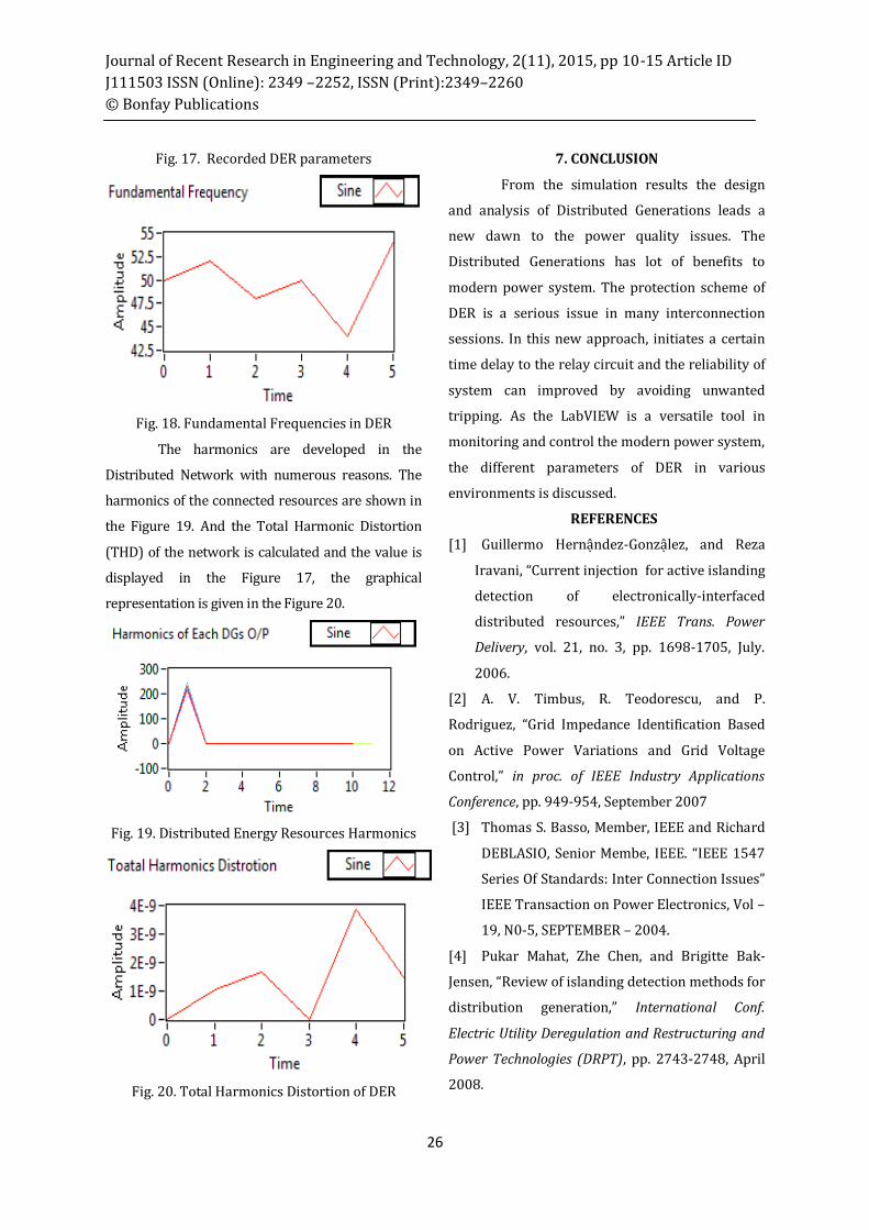
Fig. 17. Recorded DER parameters
Fig. 18. Fundamental Frequencies in DER
The harmonics are developed in the
Distributed Network with numerous reasons. The
harmonics of the connected resources are shown in
the Figure 19. And the Total Harmonic Distortion
(THD) of the network is calculated and the value is
displayed in the Figure 17, the graphical
representation is given in the Figure 20.
Fig. 19. Distributed Energy Resources Harmonics
Fig. 20. Total Harmonics Distortion of DER
7. CONCLUSION
From the simulation results the design
and analysis of Distributed Generations leads a
new dawn to the power quality issues. The
Distributed Generations has lot of benefits to
modern power system. The protection scheme of
DER is a serious issue in many interconnection
sessions. In this new approach, initiates a certain
time delay to the relay circuit and the reliability of
system can improved by avoiding unwanted
tripping. As the LabVIEW is a versatile tool in
monitoring and control the modern power system,
the different parameters of DER in various
environments is discussed.
REFERENCES
[1] Guillermo Hernậndez-Gonzậlez, and Reza
Iravani, “Current injection for active islanding
detection of electronically-interfaced
distributed resources,” IEEE Trans. Power
Delivery, vol. 21, no. 3, pp. 1698-1705, July.
2006.
[2] A. V. Timbus, R. Teodorescu, and P.
Rodriguez, “Grid Impedance Identification Based
on Active Power Variations and Grid Voltage
Control,” in proc. of IEEE Industry Applications
Conference, pp. 949-954, September 2007
[3] Thomas S. Basso, Member, IEEE and Richard
DEBLASIO, Senior Membe, IEEE. “IEEE 1547
Series Of Standards: Inter Connection Issues”
IEEE Transaction on Power Electronics, Vol –
19, N0-5, SEPTEMBER – 2004.
[4] Pukar Mahat, Zhe Chen, and Brigitte Bak-
Jensen, “Review of islanding detection methods for
distribution generation,” International Conf.
Electric Utility Deregulation and Restructuring and
Power Technologies (DRPT), pp. 2743-2748, April
2008.

Journal of Recent Research in Engineering and Technology, 2(11), 2015, pp 10-15 Article ID
J111503 ISSN (Online): 2349 –2252, ISSN (Print):2349–2260
© Bonfay Publications
27
[5] V. Menon, and M. H. Nehrir, “A hybrid
islanding detection technique using voltage
unbalance and frequency set point,” IEEE Tran.
Power Systems, vol. 22, no. 1, pp. 442-448, Feb.
2007.
[6] F. Katiraei, A. Foss, C. Abbey, and B. Strehler,
“Dynamic analysis and field verification of an
innovative anti-islanding protection schemebased
on directional reactive power detection,” in IEEE
Electrical Power Conf. (EPC 2007) ,pp. 183-188,
Oct. 2007.
[7] Houshang Karimi, Amirnaser Yazdani, and
Reza Iravani, “Negativesequence current
injection for fast islanding detection of a
distributed resource unit,” IEEE Trans. Power
Electronics., vol. 23, no. 1, pp. 298-307,
Jan.2008.
[8] N. Acharya, P. Mahat, and N. Mithulananthan,
“An analytical approach for DG allocation in
primary distribution network,” International
Journal of Electrical Power & Energy Systems, vol.
28, no. 10, pp 669-
678, Dec. 2006.
[9] Beddoes, A., Thomas, P. and Gosden, M., ‘Loss
of mains protection relay performances when
subjected to network disturbances/event’,
18th International Conference on Electricity
Distribution, Turin, June 2005.
[10] IEEE Power system relaying committee of
the power engineering society. 2003. C37,118.
IEEE Standard for Synchrophasors for Power
System.
[11] P. O’Kane, and B. Fox, “Loss of mains
detection for embedded generation by system
impedance monitoring,” in Proc. Sixth
International Conference on Developments in Power
System Protection, pp. 95-98, March 1997.
[12] S. I. Jang, and K. H. Kim, “A new islanding
detection algorithm for distributed generations
interconnected with utility networks,” in
Proc.IEEE International Conference on
Developments in Power System Protection, vol.2,
pp. 571-574, April 2004.
[13] M. Kubis, C. S .Choo. (No date) .Real-Time
Monitoring and Analysis System for Power
Quality. [Online]. National Instruments. [June
2006].
[14] A. Ferrero and S. Salicone, An Easy VI
Program to Detect Transient Disturbances in the
Supply Voltage, IEEE Transactions on
Instrumentation and Measurement, Vol. 54, No. 4:
1471 – 1474, 2005
[15] P. Daponte, M. Di Penta, Transient Meter:
A Distributed Measurement System for Power
Quality Monitoring, IEEE Transactions on Power
Delivery, Vol. 19 No. 2: 456 - 463, April 2004.
[16] M. Liserre, A. Pigazo, A. D. Aquila, and V. M.
Moreno, “Islanding Detection Method for Single-
Phase Distributed Generation Systems Based on
Inverters,” in proc. of IEEE Industrial Electronics
Society Annual Conference, pp. 1-6, November
2005.
[17] J. Yin, L. Chang, and C. Diduch, “A new
hybrid anti-islanding algorithm in grid
connected three-phase inverter system,” IEEE
Power Electronics Specialist Conf. (PESC’06),
pp. 1-7, June 2006.
[18] Jose C. M. Vieira, Walmir Freitas, Wilsun
Xu, and Andre Morelato “Performance of
frequency relays for distributed generation
protection,”IEEE Trans. Power Delivery, vol.
21, no. 3, pp. 1120-1127, July. 2006.