jp 3ga 23.110(r99) umts access stratum ; services and ... · i jp-3ga-23.110(r99)...
TRANSCRIPT
JP 3GA 23.110(R99)
UMTS Access Stratum ; Services and Functions
Version 2
October 25, 2000
THE TELECOMMUNICATION TECHNOLOGY COMMITTEE
i JP-3GA-23.110(R99)
JP-3GA-23.110(R99)UMTS Access Stratum; Services and Functions
Remarks
1.Application level of English descriptionApplication level:E3
English description is included in the text and figures of main body, annexes and appendices.
2.Relationship with international recommendations and standardsThis standard is standardized based on the Technical Specification 23.110 (Version 3.4.0) approved by 3GPP in
June 2000.
3.Departures from international recommendations3.1 Selection of optional items
None
3.2 Items of national matter
None
3.3 Changes to original standard
(1) Standards referred to in the original standard, which are replaced by TTC/ARIB standards.
Refer to Table 1.
(2) Items added to the original standard
None
(3) Items deleted from the original standard
None
(4) Items changed from the original standard
None
3.4 Difference in chapter ordering from the original standard.
There is no difference in chapter ordering from the original standard.
4.Change history
Revision Date Contents
V.1 Mar.31,2000 Newly standardized
V.2 Oct.25,2000 Revised based on the Technical Specification 23.110(Version 3.4.0) approved by 3GPP
5.IPRThere is no specific description about IPR in this standard.
6.OthersNone

ii JP-3GA-23.110(R99)
Table 1 Replaced standards referred
original standard replacement
3G TS 22.101
Title: Service aspects; Service principles
ARIB STANDARDS ARIB STD-T63-22.101
Title: IMT-2000 DS-CDMA System Service aspects; Service principles
3G TS 23.101
Title: General UMTS Architecture
TTC STANDARDS JP-3GA-23.101(R99)
Title: General UMTS Architecture
3G TS 23.107
Title: QoS Concept and Architecture
ARIB STANDARDS ARIB STD-T63-23.107
Title: IMT-2000 DS-CDMA System QoS Concept and Architecture

3G TS 23.110 3.4.0 (2000-03)Technical Specification
3rd Generation Partnership Project;Technical Specification Group Services and System Aspects
UMTS Access Stratum;Services and Functions
(Release 1999)
The present document has been developed within the 3rd Generation Partnership Project (3GPP TM) and may be further elaborated for the purposes of 3GPP.The present document has not been subject to any approval process by the 3GPP Organisational Partners and shall not be implemented.This Specification is provided for future development work within 3GPP only. The Organisational Partners accept no liability for any use of this Specification.Specifications and reports for implementation of the 3GPP TM system should be obtained via the 3GPP Organisational Partners' Publications Offices.

3GPP
3G TS 23.110 3.4.0 (2000-03)2Release 1999
Keywords
3GPP
Postal address
3GPP support office address650 Route des Lucioles - Sophia Antipolis
Valbonne - FRANCETel.: +33 4 92 94 42 00 Fax: +33 4 93 65 47 16
Internethttp://www.3gpp.org
Copyright Notification
No part may be reproduced except as authorized by written permission.The copyright and the foregoing restriction extend to reproduction in all media.
© 2000, 3GPP Organizational Partners (ARIB, CWTS, ETSI, T1, TTA,TTC).All rights reserved.

3GPP
3G TS 23.110 3.4.0 (2000-03)3Release 1999
ContentsForeword ............................................................................................................................................................5
1 Scope........................................................................................................................................................6
2 References................................................................................................................................................6
3 Definitions and abbreviations ..................................................................................................................63.1 Definitions ......................................................................................................................................................... 63.2 Abbreviations..................................................................................................................................................... 7
4 Basic Assumptions...................................................................................................................................74.1 Boundaries of the Access Stratum ..................................................................................................................... 74.2 Main design guidelines ...................................................................................................................................... 7
5 Functions location inside/outside Access Stratum...................................................................................85.1 Call Control ....................................................................................................................................................... 95.2 (Connection) Bearer Control.............................................................................................................................. 95.3 Supplementary Services (CLIP, CF etc.) ......................................................................................................... 105.4 Location Management...................................................................................................................................... 105.5 Attach/ Detach ................................................................................................................................................. 105.6 Resource management ..................................................................................................................................... 105.7 Handover ......................................................................................................................................................... 105.7.1 Handover - outside Access Stratum............................................................................................................ 105.7.2 Handover - inside Access Stratum.............................................................................................................. 105.7.3 Handover scenarios supported by the Iu interface...................................................................................... 105.7.3.1 Classification A .................................................................................................................................... 105.7.3.2 Classification B..................................................................................................................................... 115.7.3.3 Classification C..................................................................................................................................... 115.7.3.4 Classification D .................................................................................................................................... 125.8 Macrodiversity................................................................................................................................................. 125.9 Encryption........................................................................................................................................................ 125.10 Authentication of Subscriber ........................................................................................................................... 125.11 (Non source dependent coding) Compression ................................................................................................. 125.12 Source (e.g. voice or video) Coding ................................................................................................................ 125.13 Radio Channel Coding..................................................................................................................................... 125.14 UE Location Identification .............................................................................................................................. 135.15 Charging .......................................................................................................................................................... 13
6 Access Stratum services.........................................................................................................................136.1 Service Access Points (SAPs).......................................................................................................................... 146.1.1 General Control SAPs ................................................................................................................................ 156.1.2 Notification SAPs....................................................................................................................................... 156.1.3 Dedicated Control SAPs............................................................................................................................. 156.2 Operations........................................................................................................................................................ 156.2.1 General ....................................................................................................................................................... 156.2.2 Common operations ................................................................................................................................... 166.2.2.1 General Control SAP ............................................................................................................................ 166.2.2.1.1 Information broadcast ..................................................................................................................... 166.2.2.2 Notification SAPs ................................................................................................................................. 166.2.2.2.1 Paging Request, IF side................................................................................................................... 176.2.2.2.2 Notification Broadcast Request, IF side.......................................................................................... 176.2.2.2.3 Notification Indication, UE side ..................................................................................................... 176.2.2.3 Dedicated Control SAPs....................................................................................................................... 176.2.2.3.1 UE Side Initiated Connection Establishment .................................................................................. 186.2.2.3.2 Connection Release......................................................................................................................... 196.2.2.3.3 Information Transfer ....................................................................................................................... 196.2.2.3.4 IF Side Initiated Radio Access Bearer Establishment ..................................................................... 216.2.2.3.4.1 IF Side Initiated Radio Access Bearer Establishment Request, IF Side .................................... 21

3GPP
3G TS 23.110 3.4.0 (2000-03)4Release 1999
6.2.2.3.4.2 IF Side Initiated Radio Access Bearer Establishment Indication, UE Side ............................... 216.2.2.3.4.3 IF Side Initiated Radio Access Bearer Establishment Response, UE Side................................ 216.2.2.3.4.4 IF Side Initiated Radio Access Bearer Establishment Confirm, IF Side ................................... 216.2.2.3.5 IF Side Initiated Radio Access Bearer Release ............................................................................... 226.2.2.3.5.1 IF Side Initiated Radio Access Bearer Release Request, IF Side .............................................. 226.2.2.3.5.2 IF Side Initiated Radio Access Bearer Release Indication, UE Side ......................................... 226.2.3 IF side only operations ............................................................................................................................... 226.2.3.1 Dedicated control SAPs........................................................................................................................ 226.2.3.1.1 Position update indication............................................................................................................... 226.2.3.1.2 Connection loss indication .............................................................................................................. 226.2.3.1.3 Streamlining required indication..................................................................................................... 226.2.3.1.4 Branch establishment request.......................................................................................................... 236.2.3.1.5 Branch establishment confirm......................................................................................................... 236.2.3.1.6 UE location information request ..................................................................................................... 236.2.3.1.7 UE location information confirm .................................................................................................... 236.2.4 UE side only operations ............................................................................................................................. 246.2.4.1 Dedicated control SAPs........................................................................................................................ 246.2.4.1.1 Connection loss indication .............................................................................................................. 246.3 Parameters structure......................................................................................................................................... 246.3.1 Local .......................................................................................................................................................... 246.3.2 Bit string..................................................................................................................................................... 246.3.3 Enumerated ................................................................................................................................................ 246.3.4 Geographical description............................................................................................................................ 246.3.5 QoS ............................................................................................................................................................ 246.3.6 Route .......................................................................................................................................................... 246.3.7 Transaction identifier ................................................................................................................................. 256.3.8 Transaction list ........................................................................................................................................... 256.3.9 Transmission mode .................................................................................................................................... 256.3.10 AN/CN Point List....................................................................................................................................... 256.3.11 Localisation................................................................................................................................................ 25
Annex A (informative): Change history ...............................................................................................26

3GPP
3G TS 23.110 3.4.0 (2000-03)5Release 1999
ForewordThis Technical Specification (TS) has been produced by the 3rd Generation Partnership Project (3GPP).
The contents of the present document are subject to continuing work within the TSG and may change following formalTSG approval. Should the TSG modify the contents of the present document, it will be re-released by the TSG with anidentifying change of release date and an increase in version number as follows:
Version x.y.z
where:
x the first digit:
1 presented to TSG for information;
2 presented to TSG for approval;
3 or greater indicates TSG approved document under change control.
y the second digit is incremented for all changes of substance, i.e. technical enhancements, corrections, updates,etc.
z the third digit is incremented when editorial only changes have been incorporated in the document.

3GPP
3G TS 23.110 3.4.0 (2000-03)6Release 1999
1 ScopeThe present document specifies the services provided by the Access Stratum to the rest of the system. The adoptedarchitecture is given by 3G TS 23.101 [2].
The present document describes the main functions visible at the boundary between the Access Stratum and the rest ofthe system, it describes in general terms the information flows, both control and user data, over this boundary andrelevant for the Access Stratum.
The present document is the basis of the detailed specifications of the protocols which rule the information flows, bothcontrol and user data, between the Access Stratum and the parts of UMTS outside the Access Stratum, and of thedetailed specifications of the UTRAN. These detailed specifications are to be found in other Technical Specifications.
2 ReferencesThe following documents contain provisions which, through reference in this text, constitute provisions of the presentdocument.
• References are either specific (identified by date of publication, edition number, version number, etc.) ornon-specific.
• For a specific reference, subsequent revisions do not apply.
• For a non-specific reference, the latest version applies.
[1] 3G TS 22.101: "Universal Mobile Telecommunications System (UMTS): Service aspects; Serviceprinciples".
[2] 3G TS 23.101: "Universal Mobile Telecommunications System (UMTS): General UMTSArchitecture".
[3] 3G TS 23.105: "Universal Mobile Telecommunications System (UMTS): Network Principles".
[4] ITU-T Recommendation X.210 (November 1993): "Information Technology - Open SystemsInterconnection - Basic Reference Model: Conventions for the Definition of OSI Services".
[5] 3G TS 23.107: "QoS Concept and Architecture".
3 Definitions and abbreviations
3.1 DefinitionsFor the purposes of the present document, the terms and definitions given in 3G TS 23.101 [2] and the following apply.
Access Stratum: defined in [2].
Access Network: defined in [2].
Edge-Node: core network node which is connected to the URAN at a particular instance.
URAN: defined in [TBD].

3GPP
3G TS 23.110 3.4.0 (2000-03)7Release 1999
3.2 AbbreviationsFor the purposes of the present document, the following abbreviations apply:
AN Access NetworkAS Access StratumCC Call ControlDC Dedicated Control SAPCN Core NetworkFFS For Further StudyGC General Control (SAP)GPRS General Packet Radio ServiceGSM Global System for Mobile communicationsHPLMN Home Public Land Mobile NetworkIF InfrastructureME Mobile EquipmentMM Mobility ManagementMS Mobile StationNAS Non Access StratumNt Notification (SAP)PDN Packet Data NetworkPTM Point to MultipointRAN Radio Access NetworkSAP Service Access PointSAPI Service Access Point Identifier [???]SIM Subscriber Identity ModuleSMS Short Message ServiceSS Supplementary ServicesTBD To Be DefinedUE User EquipmentUMTS Universal Mobile Telecommunications SystemURAN UMTS Radio Access NetworkUSIM UMTS Subscriber Identity ModuleUSSD Unstructured Supplementary Service DataUTRA UMTS Terrestrial Radio AccessUTRAN UMTS Terrestrial Radio Access NetworkVBS Voice Broadcast ServiceVGCS Voice Group Call ServiceVPLMN Visited Public Land Mobile Network
4 Basic Assumptions
4.1 Boundaries of the Access StratumThe Access Stratum (AS) is defined in [2]. It consists of a functional grouping which includes all the layers embedded inthe URAN; and part of the layers in the User Equipment (UE) and the infrastructure (IF); i.e. the edge-node. Itsboundary is the frontier between the layers which are independent of the access technique and the ones which aredependent on it. This frontier is located in the UE (mobile boundary) and in an edge-node (fixed boundary). There is adirect or "transparent" dialogue (i.e. not interpreted by the AS) between the UE and the edge-node for the Non-AccessStratum layers.
4.2 Main design guidelines1) The Access Stratum contains all access specific functionality, e.g. all mode specific functionality in case of the
UTRAN.
3GPP
3G TS 23.110 3.4.0 (2000-03)8Release 1999
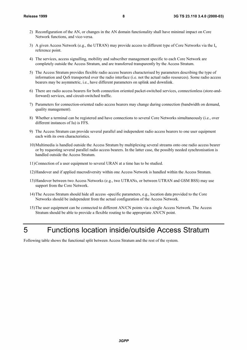
2) Reconfiguration of the AN, or changes in the AN domain functionality shall have minimal impact on CoreNetwork functions, and vice-versa.
3) A given Access Network (e.g., the UTRAN) may provide access to different type of Core Networks via the Iureference point.
4) The services, access signalling, mobility and subscriber management specific to each Core Network arecompletely outside the Access Stratum, and are transferred transparently by the Access Stratum.
5) The Access Stratum provides flexible radio access bearers characterised by parameters describing the type ofinformation and QoS transported over the radio interface (i.e. not the actual radio resources). Some radio accessbearers may be asymmetric, i.e., have different parameters on uplink and downlink.
6) There are radio access bearers for both connection oriented packet-switched services, connectionless (store-and-forward) services, and circuit-switched traffic.
7) Parameters for connection-oriented radio access bearers may change during connection (bandwidth on demand,quality management).
8) Whether a terminal can be registered and have connections to several Core Networks simultaneously (i.e., overdifferent instances of Iu) is FFS.
9) The Access Stratum can provide several parallel and independent radio access bearers to one user equipmenteach with its own characteristics.
10)Multimedia is handled outside the Access Stratum by multiplexing several streams onto one radio access beareror by requesting several parallel radio access bearers. In the latter case, the possibly needed synchronisation ishandled outside the Access Stratum.
11)Connection of a user equipment to several URAN at a time has to be studied.
12)Handover and if applied macrodiversity within one Access Network is handled within the Access Stratum.
13)Handover between two Access Networks (e.g., two UTRANs, or between UTRAN and GSM BSS) may usesupport from the Core Network.
14)The Access Stratum should hide all access -specific parameters, e.g., location data provided to the CoreNetworks should be independent from the actual configuration of the Access Network.
15)The user equipment can be connected to different AN/CN points via a single Access Network. The AccessStratum should be able to provide a flexible routing to the appropriate AN/CN point.
5 Functions location inside/outside Access StratumFollowing table shows the functional split between Access Stratum and the rest of the system.

3GPP
3G TS 23.110 3.4.0 (2000-03)9Release 1999
Table 1: Functions inside/outside the Access Stratum
LOCATION\
FUNCTION
Outside the Access Stratum Inside the Access Stratum
Call set up/release yes no(Connection) Bearer Set-Up
ReleaseCN bearer [tbd] Radio Access Bearer [tbd]
Supplementary Services yes noLocation management yes (IWF/CN related) yes (Radio related)
Attach/ Detach yes FFS, Contr expectedResource Management yes (for NAS resource) yes (for AS resource incl. radio)
Handover yes* yesMacrodiversity [ffs] yes* yes
Encryption yes yes**Authentication yes no
compression (non sourcedependent)
yes yes
source dependent coding yes noradio channel coding (could be
many)no yes (could be many)
UE location identification may be supported yesCharging yes no
NOTE *: Optionally execution. In some CNs, it may not be present but not full service will be supported (e.g. limited toRLL type of service).
NOTE **: Contributions expected to clarify the role between encryption and subscriber data.
5.1 Call ControlThis Functionality is placed in the NAS, since it manipulates the call state machine. An example is termination of Q.931message and sending of ISUP.
Not part of AS. NAS specific signalling messages, e.g. Q.931, Q.2931 and ISUP.
5.2 (Connection) Bearer ControlIt is distinguished between the bearers used in the NAS and the common bearer used in the AS (radio access bearer).
Basic principles for radio access bearers are:
1) Radio access bearers provide information transport between the non-access stratum parts of the infrastructureside (i.e. the edge node) and the user equipment side. Radio access bearers shall support real time as well as nonreal time user traffic.
2) Radio access bearers must be flexible enough to support different traffic types, activity levels, throughput rates,transfer delays and bit error rates. Attributes allowing efficient use of radio resources are crucial.
3) Efficient mapping from the traffic attributes used by non-UMTS applications, given by dominating externalnetwork technologies, to the attributes of the radio access bearer layer of the access stratum is essential.Complexity in mapping procedures should be avoided.
4) Definitions of traffic attributes and traffic management for radio access bearers shall be consistent with thepredominant networking technology on the market (e.g. N-ISDN and IP networks for UMTS phase 1). Asnetworking technologies emerge, adapted radio access bearer attributes and types shall gradually be added.
5) Radio access bearer definitions must allow for straightforward and efficient traffic management and resourcehandling of the radio resources in the access stratum.
This procedure is part of the NAS. Example are 13.0 kbit/s (for GSM speech) and 2B+D (for ISDN BRI).

3GPP
3G TS 23.110 3.4.0 (2000-03)10Release 1999
The protocols required in AS to provide a radio access bearer should be able to describe both packet switch and circuitswitch types of connections.
5.3 Supplementary Services (CLIP, CF etc.)Supplementary services are part of the NAS, since they manipulate the Call state machine.
Supplementary services are not part of AS since they manipulate the call state machine.
5.4 Location Management"Location Updating Management" and "Paging" is an existing example of Location Management.
Location Management may be supported in the NAS.
Radio related Location Management may be part of the AS.
5.5 Attach/ DetachIf the Attach/ Detach procedures are supported in the NAS they use CN specific identifiers to mark theattached/detached subscriber. As an example in GSM, the attach/detach procedure is performed on the IMSI flag, andtherefore it is a NAS functionality.
Attach/Detach may be performed in the AS using the URAN unique identifiers. This is FFS.
5.6 Resource managementThis function allocates resources for a given information stream, as to allow to convey it with a given QoS. Thisinformation stream may support either signalling data (CC, MM, ...) or user data.
Both circuit switched and packet access are supported, offering both connection oriented and connectionless services.
The AS resource management is transparent for the NAS and vice versa.
5.7 Handover
5.7.1 Handover - outside Access StratumHandover may be a NAS functionality, but it can not be expected that all CNs will support handover therefore the IWFmay take care of any required handover functionality. The AN may leave certain parameters, e.g. the address to a newIWF/CN-AN connection point, to which the IWF/CN may switch if it has the capabilities.
5.7.2 Handover - inside Access StratumHandover is performed in the AS, to hide all radio specific details from the NAS.
5.7.3 Handover scenarios supported by the Iu interfaceThe following sections describe which functions will be supported by the Iu interface. Some functions have no impacton the Iu interface and therefore will be supported de-facto, nevertheless they are explicitly mentioned for completenessof the scenarios.
5.7.3.1 Classification A
Classification A describes the way the handover is prepared:

3GPP
3G TS 23.110 3.4.0 (2000-03)11Release 1999
HO A1: the network has informed the target cell before the MS changes cell;
HO A2: the network has not informed the target cell before the MS changes cell;
HO A3: the mobile has informed the target cell before it leaves the source cell.
HO A1 is typical of the existing handover in GSM.
HO A2 reflects the call re-establishment in GSM, mobile directed handovers in general, or even GPRS to some extent(although the GPRS vocabulary is different).
HO A1, HO A2 and HO A3 shall be supported by the service primitives of the Iu interface.
5.7.3.2 Classification B
Classification B describes the way the decision to initiate a handover is taken:
HO B1: decision is taken by the terminal;
HO B2: decision is taken by the network.
When the network takes the decision, it can be either in the RAN (HO B2a), or in the CN (probably based oninformation provided by the RAN and/or the MS) (HO B2b).
In order to keep the radio independence from the CN, it would be desirable that the decision be taken only in the RAN.This means that a communication mechanism is needed between URANs, that interface being logically different fromthe Iu interface.
HO B1 and HO B2 shall be supported by the service primitives of the Iu interface.
NOTE 1: FFS:For HO B2 cases, handover initiation/decisions shall be taken by the source URAN.
NOTE 2: FFS: There is a URAN to URAN signalling mechanism transparent to the CN. A standardised protocolwill be implemented across that interface to allow handover decisions by the URAN in HO B2 cases.
5.7.3.3 Classification C
Classification C concerns the kind of handover performed:
1) intra-cell handover;
2) intra-URAN handover;
3) inter-URAN handover (without change of CN access point);
4) intra-CN handover with same URAN type;
5) intra-CN handover with different URAN type;
6) inter-CN handover with same URAN type and same CN type;
7) inter-CN handover with different URAN type and same CN type;
8) inter-CN handover with same URAN type and different CN type;
9) inter-CN handover with different URAN type and different CN type;
10)inter-CN handover without change of URAN.
The type of URAN type should be relatively transparent to the Iu interface.
Regarding handovers across multiple CN, it is proposed that this is supported (and this is already possible with GSM).
C1 to C7 scenarios shall be supported by the service primitives of the Iu interface.
NOTE: FFS: scenarios C8 to C10 shall be supported by the service primitives of the Iu interface.

3GPP
3G TS 23.110 3.4.0 (2000-03)12Release 1999
5.7.3.4 Classification D
Regarding how a handover is performed, there is the possibility to either have the notion of anchor point, or not to haveit. Example is circuit switched GSM, using anchor points, and GPRS, not using that notion.
Furthermore, the notion of anchor point may be handled differently for the signalling plane and the transmission plane.
The notion of anchor point shall be supported by the service primitives of the Iu interface.
NOTE 1: FFS: the notion of transmission plane anchor point is supported by the service primitives of the Iuinterface.
NOTE 2: FFS: the notion of signalling plane anchor point is supported by the service primitives of the Iu interface.
NOTE 3: FFS: the anchor points for the signalling plane and transmission plane need not necessarily be the same oreven exist simultaneously. The flexibility should be left in UMTS by the Iu service principles.
5.8 Macrodiversity (if needed, dependent of the choice of multiple access technology)
Not all IWF/CNs will support macrodiversity.
Macrodiversity may be supported in the AS, dependent on the choice of multiple access technology.
5.9 EncryptionThe NAS may support encryption to protect the transmitted data.
The AS needs to support encryption to prevent from eavesdropping at the radio interface.
5.10 Authentication of SubscriberSubscriber data is stored in the NAS and therefore authentication should be considered a NAS functionality.
NAS data is not stored in the URAN, and subscriber authentication can therefore not be a URAN functionality.
5.11 (Non source dependent coding) CompressionNAS may support compression.
The AS should support compression to optimise usage of radio resources.
5.12 Source (e.g. voice or video) CodingSource coding is different dependent on IWF/CN and is therefore a NAS functionality.
5.13 Radio Channel CodingRadio Channel coding is needed due to the radio interface and could therefore be considered a radio functionality. RadioChannel coding is not a NAS functionality.
Radio Channel coding is supported by URAN.

3GPP
3G TS 23.110 3.4.0 (2000-03)13Release 1999
5.14 UE Location IdentificationThe UE location identification may be supported by the UE and/or the access network side of the AS; i.e., URAN; e.g.,as defined in the GSM LCS (Location Services) specifications or by some other means. The UE location identification isprovided to identify the likely location of specific UEs. This is meant to be used for charging, location-based services,lawful interception, emergency calls, etc., as well as the positioning services.
When location identification is supported by URAN, the following apply:
1) URAN obtains �Area ID� and/or geographic co-ordinates with uncertainty parameters for identification of the likelylocation of UE, to be sent to the NAS entity side of the CN (i.e., edge node) �Area ID� represents either a radioaccess cell/sector or a geographic area. �Area ID� is coded in the same format as Cell Global Identification (CGI),for compatibility to GSM.
2) Location information is categorised to two levels of accuracy. The Basic Level of information is what URAN obtainswithout extra signalling with the UE. The advanced level is obtained through extra signalling for positioning. Bothlevels can be used for both, Positioning services and other applications.
3) Location information is always at least obtained from URAN by the appropriate edge node(s) at the activation of aCall/PDP Context. Mechanism to make it possible to obtain the location information at the release of a Call/PDPContext should be specified. Location information sent to the edge node at other occasions is on the basis ofasynchronous requests from the edge node to URAN. An edge node can request URAN to send the locationinformation with the two types of requests, Type 1 (Direct request) where URAN sends location information onlyonce at the request and Type 2 (Event request) where URAN sends location information at each specified event (e.g.Cell Update) requested by the edge node.
5.15 ChargingThe functions related to charging are not part of the AS. These functions are mainly:
- charging information generation;
- charging processing.
6 Access Stratum servicesThe modelling of the services follow the basic principles as set by ITU-T Recommendation X.210 [4]. In thisrecommendation the following figure is given as an example for peer-to-peer connection-mode services.
TISO2530-94/d03
ServiceUser A
ServiceUser B
OSI-Service-Provider
Request(requestor.submit)
Confirm(requestor.deliver)
Indication(acceptor.deliver)
Response(acceptor.submit)
Figure 1: Example of a peer-to-peer connection-mode service [4]
For connectionless-mode services the basic primitives are "request" and "indication".

3GPP
3G TS 23.110 3.4.0 (2000-03)14Release 1999
6.1 Service Access Points (SAPs)The SAPs offered by the Access Stratum (AS) to the rest of the system (Non Access Stratum: NAS) are reflected in thefollowing figure.
UE-Uu CN-Iu
NAS NAS
IF-Uu RAN-Iu
Edge nodeRANUE
Infrastructure SideUser Equipment Side
AS AS
RNC Functions
GC GC GCNt
GC GC
GCNtNt
Nt Nt
Nt
DC
DC DC DC
DC
DC
Uu Svcs: e.g., RRC Iu Svcs: e.g., RANAP
: SAPs
Figure 2: Service Access Points (SAPs) offered by the Access Stratum (AS)
For the time being, the SAPs offered be the AS are symmetric, i.e. the same SAPs are offered on the infrastructure side(CN-AS) and on the user equipment side (UE-AS). These SAPs are:
GC: General Control (see 6.1.1 for a general presentation and 6.2.2.1 for a detailed information).
Nt: Notification (see 6.1.2 for a general presentation and 6.2.2.2 for a detailed information).
DC: Dedicated Control (see 6.1.3 for a general presentation and 6.2.2.3 for a detailed information).
Note:Broadcast and Multicast services can not be described using the services and functions defined so far in the presentdocument. The nature of Broadcast and Multicast services, like Cell Broadcast Service (CBS), is very different fromother specified services. The following model characteristics are missing to fulfil the CBS requirements, namely:
1. CBS uses two segments with different QoS requirements to deliver CB messages to the UE:
1a. From Cell Broadcast Center (CBC) to RNC, a SAP is required where for instance, 1 second turnaround time,interactive class, with a reliable transport is required.
1b. From RNC to UE, a SAP is required where for instance, a maximum delay of 10 seconds and a background classis required.
2. Because of (item 1), the service primitives used by each of the segments may also be different; i.e., the relatedSAPs to those primitives may differ in the two segments and a combination of GC, Nt, and DC SAPs requiresstudy.
3. CBS traffic is asymmetric in nature. The communication flow is only in one direction from the CBC to the UE .There is no uplink channel needed and the UE can not initiate a communication or request specific information.
At least two changes are envisaged and thus detailed contributions are expected:
3GPP
3G TS 23.110 3.4.0 (2000-03)15Release 1999
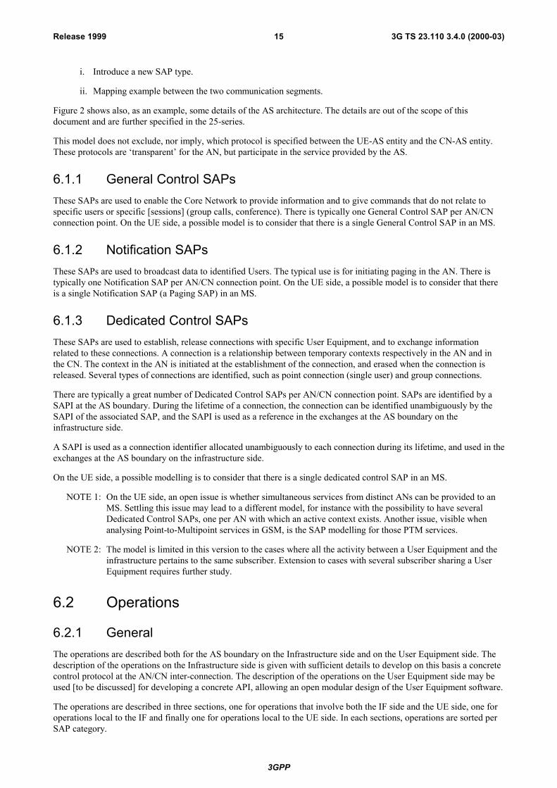
i. Introduce a new SAP type.
ii. Mapping example between the two communication segments.
Figure 2 shows also, as an example, some details of the AS architecture. The details are out of the scope of thisdocument and are further specified in the 25-series.
This model does not exclude, nor imply, which protocol is specified between the UE-AS entity and the CN-AS entity.These protocols are �transparent� for the AN, but participate in the service provided by the AS.
6.1.1 General Control SAPsThese SAPs are used to enable the Core Network to provide information and to give commands that do not relate tospecific users or specific [sessions] (group calls, conference). There is typically one General Control SAP per AN/CNconnection point. On the UE side, a possible model is to consider that there is a single General Control SAP in an MS.
6.1.2 Notification SAPsThese SAPs are used to broadcast data to identified Users. The typical use is for initiating paging in the AN. There istypically one Notification SAP per AN/CN connection point. On the UE side, a possible model is to consider that thereis a single Notification SAP (a Paging SAP) in an MS.
6.1.3 Dedicated Control SAPsThese SAPs are used to establish, release connections with specific User Equipment, and to exchange informationrelated to these connections. A connection is a relationship between temporary contexts respectively in the AN and inthe CN. The context in the AN is initiated at the establishment of the connection, and erased when the connection isreleased. Several types of connections are identified, such as point connection (single user) and group connections.
There are typically a great number of Dedicated Control SAPs per AN/CN connection point. SAPs are identified by aSAPI at the AS boundary. During the lifetime of a connection, the connection can be identified unambiguously by theSAPI of the associated SAP, and the SAPI is used as a reference in the exchanges at the AS boundary on theinfrastructure side.
A SAPI is used as a connection identifier allocated unambiguously to each connection during its lifetime, and used in theexchanges at the AS boundary on the infrastructure side.
On the UE side, a possible modelling is to consider that there is a single dedicated control SAP in an MS.
NOTE 1: On the UE side, an open issue is whether simultaneous services from distinct ANs can be provided to anMS. Settling this issue may lead to a different model, for instance with the possibility to have severalDedicated Control SAPs, one per AN with which an active context exists. Another issue, visible whenanalysing Point-to-Multipoint services in GSM, is the SAP modelling for those PTM services.
NOTE 2: The model is limited in this version to the cases where all the activity between a User Equipment and theinfrastructure pertains to the same subscriber. Extension to cases with several subscriber sharing a UserEquipment requires further study.
6.2 Operations
6.2.1 GeneralThe operations are described both for the AS boundary on the Infrastructure side and on the User Equipment side. Thedescription of the operations on the Infrastructure side is given with sufficient details to develop on this basis a concretecontrol protocol at the AN/CN inter-connection. The description of the operations on the User Equipment side may beused [to be discussed] for developing a concrete API, allowing an open modular design of the User Equipment software.
The operations are described in three sections, one for operations that involve both the IF side and the UE side, one foroperations local to the IF and finally one for operations local to the UE side. In each sections, operations are sorted perSAP category.

3GPP
3G TS 23.110 3.4.0 (2000-03)16Release 1999
Request and confirm primitives are always toward the Access Stratum. Indication and response primitives are alwaysfrom the Access Stratum.
6.2.2 Common operations
6.2.2.1 General Control SAP
6.2.2.1.1 Information broadcast
This operation consists in the broadcast from IF toward User Equipment of some information in some geographical area.This information is to be used by the User Equipment for instance to choose among access points or to be taken intoaccount during initial access. The information can also be destinated to an application.
NOTE: This concerns only information to be broadcasted on behalf of Non Access Strata. Other information maybe broadcasted for the internal use of the Access Stratum.
6.2.2.1.1.1 Information broadcast request, IF side
The parameters are:
Category enumerated (access pointselection, initial access, application)
Geographical area geographical areaInformation to broadcast bit string
The size of the information to broadcast is not bound by this description, but may be constrained by the access system.
The geographical area is used by the AN to determine which access points are concerned. The rules are not specified inthe external specification of the AS, but must exist and must be consistent with other translations between geographicaldescriptions and access points (e.g., in the connection establishment).
The category is used by the AN to determine priority and more generally the parameters governing informationrepetition over time.
NOTE: The category field could be enhanced, e.g., to allow a more precise control of priorities and repetitions.
6.2.2.1.1.2 Information Broadcast Indication, UE Side
The parameters are:
Access point reference localBroadcast information bit string
The access point reference identifies the point on the access boundary (e.g., the cell) where the information was received.
NOTE: The access point reference is a local reference, to be used in other primitives at the AS/NAS boundary inthe same UE.
6.2.2.2 Notification SAPs
Notification operations consists of sending information to a dedicated user/terminal, or a group of users/terminals over adefined geographic area.
Typically the request is forwarded to the user/terminal on a broadcast resource. If the AN knows of an existingsignalling relation to the user/terminal, the information might be sent through the existing relation, according to AccessStratum specifications.
3GPP
3G TS 23.110 3.4.0 (2000-03)17Release 1999
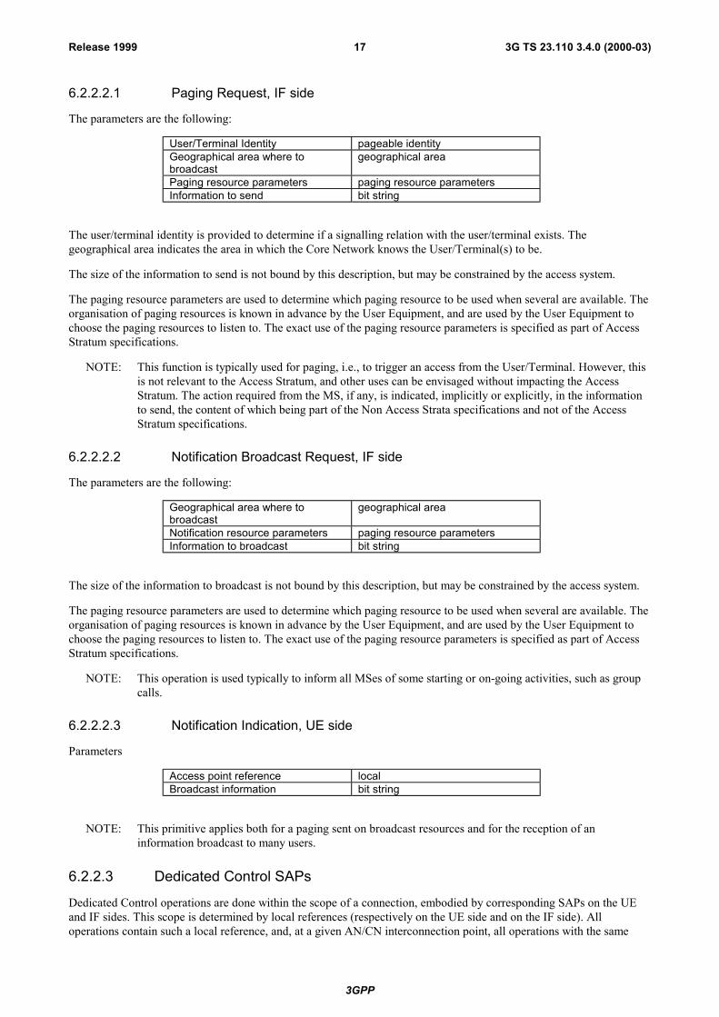
6.2.2.2.1 Paging Request, IF side
The parameters are the following:
User/Terminal Identity pageable identityGeographical area where tobroadcast
geographical area
Paging resource parameters paging resource parametersInformation to send bit string
The user/terminal identity is provided to determine if a signalling relation with the user/terminal exists. Thegeographical area indicates the area in which the Core Network knows the User/Terminal(s) to be.
The size of the information to send is not bound by this description, but may be constrained by the access system.
The paging resource parameters are used to determine which paging resource to be used when several are available. Theorganisation of paging resources is known in advance by the User Equipment, and are used by the User Equipment tochoose the paging resources to listen to. The exact use of the paging resource parameters is specified as part of AccessStratum specifications.
NOTE: This function is typically used for paging, i.e., to trigger an access from the User/Terminal. However, thisis not relevant to the Access Stratum, and other uses can be envisaged without impacting the AccessStratum. The action required from the MS, if any, is indicated, implicitly or explicitly, in the informationto send, the content of which being part of the Non Access Strata specifications and not of the AccessStratum specifications.
6.2.2.2.2 Notification Broadcast Request, IF side
The parameters are the following:
Geographical area where tobroadcast
geographical area
Notification resource parameters paging resource parametersInformation to broadcast bit string
The size of the information to broadcast is not bound by this description, but may be constrained by the access system.
The paging resource parameters are used to determine which paging resource to be used when several are available. Theorganisation of paging resources is known in advance by the User Equipment, and are used by the User Equipment tochoose the paging resources to listen to. The exact use of the paging resource parameters is specified as part of AccessStratum specifications.
NOTE: This operation is used typically to inform all MSes of some starting or on-going activities, such as groupcalls.
6.2.2.2.3 Notification Indication, UE side
Parameters
Access point reference localBroadcast information bit string
NOTE: This primitive applies both for a paging sent on broadcast resources and for the reception of aninformation broadcast to many users.
6.2.2.3 Dedicated Control SAPs
Dedicated Control operations are done within the scope of a connection, embodied by corresponding SAPs on the UEand IF sides. This scope is determined by local references (respectively on the UE side and on the IF side). Alloperations contain such a local reference, and, at a given AN/CN interconnection point, all operations with the same
3GPP
3G TS 23.110 3.4.0 (2000-03)18Release 1999
local reference from the establishment event to the release event pertain to the same connection. The correspondencebetween Dedicated Control SAPs on the UE and IF side is dynamic, and established through the connectionestablishment operations.
The local connection references have only a local scope, and their values do not necessarily have any predictablerelationship with the corresponding reference local to the other side, or with a reference used over some interface tomultiplex the messages pertaining to the connection with messages pertaining to other connections.
6.2.2.3.1 UE Side Initiated Connection Establishment
This operation consists in the establishment of a new connection at the initiative of NAS on the User Equipment side.
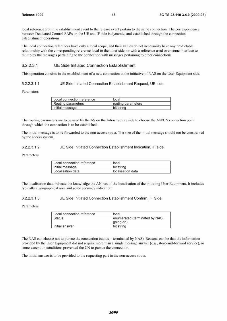
6.2.2.3.1.1 UE Side Initiated Connection Establishment Request, UE side
Parameters
Local connection reference localRouting parameters routing parametersInitial message bit string
The routing parameters are to be used by the AS on the Infrastructure side to choose the AN/CN connection pointthrough which the connection is to be established.
The initial message is to be forwarded to the non-access strata. The size of the initial message should not be constrainedby the access system.
6.2.2.3.1.2 UE Side Initiated Connection Establishment Indication, IF side
Parameters
Local connection reference localInitial message bit stringLocalisation data localisation data
The localisation data indicate the knowledge the AN has of the localisation of the initiating User Equipment. It includestypically a geographical area and some accuracy indication.
6.2.2.3.1.3 UE Side Initiated Connection Establishment Confirm, IF Side
Parameters
Local connection reference localStatus enumerated (terminated by NAS,
going on)Initial answer bit string
The NAS can choose not to pursue the connection (status = terminated by NAS). Reasons can be that the informationprovided by the User Equipment did not require more than a single message answer (e.g., store-and-forward service), orsome exception conditions prevented the CN to pursue the connection.
The initial answer is to be provided to the requesting part in the non-access strata.

3GPP
3G TS 23.110 3.4.0 (2000-03)19Release 1999
6.2.2.3.1.4 UE Side Initiated Connection Establishment Response, UE side
Parameters
Local connection reference localStatus enumerated (terminated by NAS,
terminated by AS, going on)Initial answer bit string
The initial answer is not provided in the case the status is 'terminated by AS'. The status 'going on' and 'terminated byNAS' indicates that the initial message was delivered to the NAS; on the other hand, the status 'terminated by AS' canhappen whether or not the initial message was delivered to the NAS.
6.2.2.3.2 Connection Release
This operation is the termination of a connection, at the request of non-access strata on the Infrastructure side. The useof this operation may lead to the non-completion of other previously started operations in the same connection (e.g.,transparent data transfer).
6.2.2.3.2.1 IF Initiated Connection Release Request, IF Side
Parameter
Local connection reference local
6.2.2.3.2.2 IF Initiated Connection Release Indication UE side
Parameter
Local connection reference local
6.2.2.3.3 Information Transfer
These operations allow the transfer of messages between Non-Access Strata elements on each side of the accessinterface.
The service is essentially that of a transport layer, with multiplexing, and possibly guarantee of order and correcttransmission (transmission difficulties lead to connection loss), including the effect of user movements. The operationcaters only for transmission from AS boundary to access boundary. Upper layers of protocol are typically added foraddressing and routing beyond this boundary.
Several independent streams can exist simultaneously on the same connection, as distinguished by a routing andtransaction identifiers. Message order is guaranteed, if applicable, on a stream basis. Routing identifiers are typicallyused to indicate originator and destination (e.g., USIM to Home, ME to Serving, and also distinctions such as GSMbetween MM and CC for instance...). Transaction identifiers are used to distinguish streams with the same originator anddestination. Messages can be sent within a transaction or not. Transactions are explicitly set up and released, either in-band (i.e., together with information transfer) or out-band. Transaction identifiers have only a local significance.
NOTE 1: There is a difficulty behind the message order. In some cases it may be important to keep message order ina combination of streams, e.g., within a route, or even involving two routes. The model presented so far istoo simple to cope with such cases.
A quality of service indication is present in sending requests. This covers such aspects as message order, effect on otheron-going traffic (e.g., speech pre-emption), delay. A finite number of quality of service classes will be identified, and theone to apply to a message indicated.
With each transaction is associated a default quality of service, established at transaction establishment or by asubsequent modification request.
A transmission mode indication is present in reception indications. This gives information from the Access Stratum onthe aspects of the transmission related to service quality of service (e.g., speech has been pre-empted).
3GPP
3G TS 23.110 3.4.0 (2000-03)20Release 1999
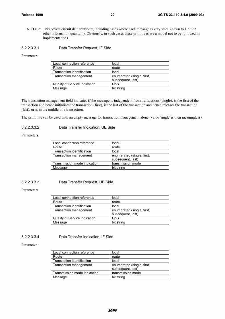
NOTE 2: This covers circuit data transport, including cases where each message is very small (down to 1 bit orother information quantum). Obviously, in such cases these primitives are a model not to be followed inimplementations.
6.2.2.3.3.1 Data Transfer Request, IF Side
Parameters
Local connection reference localRoute routeTransaction identification localTransaction management enumerated (single, first,
subsequent, last)Quality of Service indication QoSMessage bit string
The transaction management field indicates if the message is independent from transactions (single), is the first of thetransaction and hence initialises the transaction (first), is the last of the transaction and hence releases the transaction(last), or is in the middle of a transaction.
The primitive can be used with an empty message for transaction management alone (value 'single' is then meaningless).
6.2.2.3.3.2 Data Transfer Indication, UE Side
Parameters
Local connection reference localRoute routeTransaction identification localTransaction management enumerated (single, first,
subsequent, last)Transmission mode indication transmission modeMessage bit string
6.2.2.3.3.3 Data Transfer Request, UE Side
Parameters
Local connection reference localRoute routeTransaction identification localTransaction management enumerated (single, first,
subsequent, last)Quality of Service indication QoSMessage bit string
6.2.2.3.3.4 Data Transfer Indication, IF Side
Parameters
Local connection reference localRoute routeTransaction identification localTransaction management enumerated (single, first,
subsequent, last)Transmission mode indication transmission modeMessage bit string

3GPP
3G TS 23.110 3.4.0 (2000-03)21Release 1999
6.2.2.3.4 IF Side Initiated Radio Access Bearer Establishment
These operations allow the transfer of control messages for radio access bearer establishment between non-access strataelements on each side of the access interface. The operations pertain to the connection identified by the local connectionreference parameter. The operations allow the IF side to initialise a radio access bearer. The operation also implies arequest to the AS to allocate transmission resources to the radio access bearer.
A radio access bearer identification uniquely identifies the radio access bearer. It is used in all primitives that pertain tothe radio access bearer. It also serves as the binding to a NAS call.
The Iu bearer identification identifies the Iu connection.
A quality of service request specifies the bearer characteristics that apply to the radio access bearer.
6.2.2.3.4.1 IF Side Initiated Radio Access Bearer Establishment Request, IF Side
Parameters
Local connection reference local
Radio access bearer identification bit stringIu bearer identification bit string
Quality of Service request QoS
6.2.2.3.4.2 IF Side Initiated Radio Access Bearer Establishment Indication, UE Side
Parameters
Local connection reference local
Radio access bearer identification bit string
Iu bearer identification bit string
6.2.2.3.4.3 IF Side Initiated Radio Access Bearer Establishment Response, UE Side
Parameters
Local connection reference local
Radio access bearer identification bit string
Status enumerated (terminated by NAS,going on)
6.2.2.3.4.4 IF Side Initiated Radio Access Bearer Establishment Confirm, IF Side
Parameters
Local connection reference local
Radio access bearer identification bit string
Status enumerated (terminated by NAS,terminated by AS, going on)

3GPP
3G TS 23.110 3.4.0 (2000-03)22Release 1999
6.2.2.3.5 IF Side Initiated Radio Access Bearer Release
These operations allow the transfer of radio access bearer release messages between non-access strata elements on eachside of the access interface. The operations pertain to the connection identified by the local connection referenceparameter. The operations allow IF side to release a radio access bearer.
NOTE: A radio access bearer release procedure is normally initiated by the IF side. Abnormal cases such astermination by the AS are FFS.
6.2.2.3.5.1 IF Side Initiated Radio Access Bearer Release Request, IF Side
Parameters
Local connection reference local
Radio access bearer identification bit string
6.2.2.3.5.2 IF Side Initiated Radio Access Bearer Release Indication, UE Side
Parameters
Local connection reference local
Radio access bearer identification bit string
6.2.3 IF side only operations
6.2.3.1 Dedicated control SAPs
6.2.3.1.1 Position update indication
Parameters
Local connection reference localPosition position
6.2.3.1.2 Connection loss indication
Parameters
Local connection reference local
6.2.3.1.3 Streamlining required indication
This operation is used by the AS to indicate that the connection runs the risk to be aborted unless a streamlining is done.
Parameters
Local connection reference localProposed list of alternative AN/CNpoints
AN/CN point list

3GPP
3G TS 23.110 3.4.0 (2000-03)23Release 1999
6.2.3.1.4 Branch establishment request
This operation establishes a new branch supporting dedicated mode transport for a given UE.
Parameters
Local connection reference localTransaction list transaction list
The transaction list describes the transactions for which the establishment prior the first transmission of data is required.
6.2.3.1.5 Branch establishment confirm
This indicates that the branch is successfully established up to the UE and can then be used for transmission. As a result,the NAS may decide to remove the old branch.
Parameters
Local connection reference local
6.2.3.1.6 UE location information request
This operation is sent from the NAS entity inside the CN (i.e. edge node) to the access network side of AS (i.e. URAN)to request the location information of a specific UE.
Parameters:
Local connection reference localLevel of accuracy basic level or advanced levelType of request direct request or event requestEvent conditions to send information
The level of accuracy describes the granularity required on the UE location information, either basic or advanced. Thetype of request describes whether the request is to get the current UE location or to get the location when someconditions specified by event are satisfied.
6.2.3.1.7 UE location information confirm
This operation is sent in response to the UE location information request operation.
Parameters:
Local connection reference localArea ID UE location information in terms of CGI formatGeographic coordinates UE location information in terms of coordinatesEvent conditions met
The Area ID is to be formatted in accordance with the CGI (Cell Global Identity). The geographic co-ordinatesrepresents the physical co-ordinates on the earth and uncertainty parameters.
[To be completed]

3GPP
3G TS 23.110 3.4.0 (2000-03)24Release 1999
6.2.4 UE side only operations
6.2.4.1 Dedicated control SAPs
6.2.4.1.1 Connection loss indication
Parameters
Local connection reference local
[To be completed]
6.3 Parameters structure
6.3.1 LocalThe structure is not relevant in the scope of this document, and can be decided on an implementation basis.
6.3.2 Bit stringA finite ordered sequence of bit values.
6.3.3 EnumeratedThe parameter can take one value out of a list explicitly given.
6.3.4 Geographical descriptionTBI
6.3.5 QoSThis section describes the radio access bearer (RAB) by referencinga list of attributes related to the QoS. The radioaccess bearers are divided into two categories:
- Restricted radio access bearers;
- Unrestricted radio access bearers.
An unrestricted radio access bearer is meant for data requiring bit sequence integrity (;e.g., N-ISDN data transport),whereas a restricted radio access bearer contains a description of the nature of the information (;e.g., encoded voice).For a restricted radio access bearer, the characteristics are implicitly given.
The characterisation of a radio access bearer is made by using a set of attributes. A radio access bearer attribute is aspecific characteristic that distinguishes it from other radio access bearer services. Refer to ref. [5] for a list of these QoSattributes. Particular values are also indicated in that specification for different services.
In order to describe the desired radio access bearer service, QoS attributes are defined at the SAP. Note that it is notnecessary, nor meaningful to support all possible combinations of parameter settings.
NOTE: In case of an unrestricted radio access bearer, for every SDU provided at the SAP, bit sequence integrityshould be maintained.
6.3.6 RouteTBI
3GPP
3G TS 23.110 3.4.0 (2000-03)25Release 1999
6.3.7 Transaction identifierLocal.
6.3.8 Transaction listA list of transactions, each described by a transaction identifier (local) and by QoS parameters.
6.3.9 Transmission modeTBI
6.3.10 AN/CN Point ListTBI
6.3.11 LocalisationTBI

3GPP
3G TS 23.110 3.4.0 (2000-03)26Release 1999
Annex A (informative):Change history
Document history23.110 3.0.0 Approved at SMG#28. Document for Transfer to TSG-SA
Document history0.0.0 04.04.97 Initial Draft; preliminarily indicated as 23.yy
0.1.0 19.05.97 Second Draft; major improvements in clause 4.2
0.1.1 12.06.97 Revised version according to - decisions during the meeting 20-22.05.97, Sophia Antipolis - ETSI drafting rules,renamed as "23.10"
0.2.0 07.07.97 Revised version according to decisions during the meeting 30.06.-04.07.97, SophiaAntipolis. Major improvements in clause 5.
0.2.1 28.08.97 Revised version according to decisions during the meeting 30.06.-04.07.97, SophiaAntipolis. Some changes in clause 5.
0.3.0 22.09.97 Renumbered due to ETSI Drafting Rules, no changes since 0.2.1
0.3.1 12.11.97 Some editorial changes, in particular adding notes to invite contributions in order toalign "older parts" of the document and "scope"
0.4.0 08.01.98 Revised version according to decisions during the meeting 17.-21.11.97, Kista: - adoption of document incl. title to the scope - improvements in clauses 4, 4.3.6 and 5.2.2.2.
0.5.0 23.01.98 Revised version according to decisions during the meeting 19.-21.01.98, Malmö: - figure 1 in clause 5.1 added
0.6.0 1998-04 Revised version according to decisions during the meeting 23.-27.03.98, BadAibling:- chapter 4 restructured (=> new chapter 5)- table on functions in-/outside Access stratum revised- some improvements in new chapter 5.6
0.6.1 1998-06 No changes since 0.6.0 but deletion of revision marks and reformatting to papersize "LETTER" instead of "A4"
0.7.0 1998-08 Revisions as agreed on TD 98s357 in June meeting (Chicago).
NOTE: Other agreed revisions could not be inserted as the relevant documentswere not electronically available (TDocs 466, 467, 469, 476)

3GPP
3G TS 23.110 3.4.0 (2000-03)27Release 1999
0.7.1 1998-08 Editorial changes:- Some information from X.210 added.- some further textual alignment to the current state of 23.01
0.8.0 1998-08 Revisions as agreed in August meeting (Sophia Antipolis).
NOTE: Revisions according to TDocs 466, 467, 469, 476 are integrated also.
0.8.1 1998-09 Editorial alignment due to rapporteur´s notes on revisions as provided by TD98s654 and additional text alignment.
1.0.0 1998-09 Version 1.0.0 for presentation for information to SMG#27
1.0.1 draft 1998-11 Editorial updates from ver. 0.8.0 to ver. 0.8.1, and text alignments.
Addition of primitives, sections 6.2.2.3.4 and 6.2.2.3.5, for Control messages(Dedicated Control SAP) - RAB control procedures, Tdoc 98S720 (Rome).
1.0.1 1998-12 Addition of editorial comments from November (Castle Combe) meeting.
1.1.0 1999-01 Replacement of previous Section 5.14, Terminal Positioning, by new Section: UELocation Identification. With two enumerated bullet items, as agreed in the SanFrancisco meeting.
1.2.0 1999-02 Addition of third enumerated item into section 5.14. In same section, an editor´snote was inserted, regarding the need of primitives and operations, when thelocation services item is finalized. Title of section 5.4, replaced from �MSTracking� to �Location Management�. In Table 1, replacement of �UE positioning�to �UE location identification� and �UE Tracking� to �UE location management�.Remove superfluous editor`s notes throughout the specification.
2.0.0 1999-02 Update in revision numbering for presentation to SMG#28 and provision to 3GPPfor their baseline documentation.
3.0.0 1999-02 Approved at SMG#28. Document for Transfer to TSG-SA
3.1.0 1999-03 Addition of background information on UE location identification to section 5.14.Addition of primitives related to UE location information, sections 6.2.3.1.6-7: UElocation information request and confirm, respectively. Both updates approved inS2#3, Nynaeshamn.
Update related to transcoder location at the core network and source dependingcoding belonging to the non-access stratum. Updates agreed in Ad hoc in Februaryin Paris and approved in S2#3. Table 1, editorial section 5.12, section 6.3.5, QoS,and Table A.1 - speech codec in access stratum.
3.2.0 1999-11 Inclusion of CR 002 (editorial) and CR003 (removal of the QoS parameters) asagreed by TSG SA#5.
3.3.0 2000-01 Inclusion of CR004 (note on CBS functions) and introduction of the figure in CR003 (removal of the QoS parameters) not introduced by error in v.3.2.0, asapproved by TSG SA#6.
3.4.0 2000-04 Inclusion of CR005 to clarify that the RAB identity can be used to by NASelements to bind a RAB to the NAS API or corresponding.