jumo nesos r01 ls data sheet 408301 page 1/16-802 *pe+ &r .* 'holyhu\ dgguhvv...
TRANSCRIPT

V6.00/EN/00699316/2020-02-19
Page 1/16Data Sheet 408301
40830100T10Z001K000
JUMO NESOS R01 LSFloat Switch in Miniature Form
Applications• Point level measurement of liquids in storage tanks, containers, oil sumps, and tanks• Water and wastewater treatment• Mechanical and plant engineering• Shipbuilding• Energy technology• Tempering equipment
Brief descriptionThe point level measurement is carried out according to the Archimedes' principle for liquids. Thefloat moves along the guide tube as the level rises or falls. The magnet in the float actuates thereed contact(s) installed in the guide tube with its magnetic field. The switching status of the reedcontact can be evaluated and processed through downstream electronic components, relays orcontactors. Alarms, pumps, signal lamps, valves, and horns are typically switched via a contactprotection relay.
Compact versions with diameters from 27 mm are available for applications involving low instal-lation heights and tank openings. Variants with a connecting plug help to minimize mountingwork.
Depending on the variant ordered, various electrical connections, process connections, guidetube lengths, floats, and number of and positions of contacts as well as their function (SPST-NO[N/O contact], SPST-NC [N/C contact], SPDT-CO [changeover contact], and bistable contacts)are available.
With the optional temperature sensor, both the point level measurement and the temperature canbe acquired via just one measuring point. Variants for monitoring the reed contact temperatureare also available.
Variants with an intrinsically safe [Ex i] design and flameproof enclosure [Ex d] are available forapplications involving explosion protection, as are approvals for shipbuilding. No isolating switchamplifier is required for installations with a flameproof enclosure.
Customer benefits• Cost-effective installation and mounting, due to spring-cage terminals (Push-In®),
for example• Reduced operating costs due to maintenance-free device design• Price-performance ratio optimized through the use of standard components• No isolating switch amplifier required for [Ex d] (flameproof enclosure) applications
Type 408301
Special features• Approvals for shipbuilding and
explosion protection are available• High switching voltages and switching
currents• Wide media temperature range
from -52 to +240 °C• Wide pressure range from -1 to +35 bar• Up to 4 switching outputs are user-defin-
able as N/O contact, N/C contact,changeover contact, and bistable contact
• Temperature sensor/temperature switchare available
Approvals and approval marks

V6.00/EN/00699316/2020-02-19
Page 2/16Data Sheet 408301
40830100T10Z001K000
Technical dataGeneral Information
Mechanical features
Function principle Magnetic float switch with reed contactInstallation position (vertical) ±30°Switching point accuracya ±2 mmSwitching function (potential-free) 01 SPST-NO 02 SPST-NC 10 SPST-NO
Switching voltage (max.)b AC 175 V DC 175 V AC 175 V DC 175 V AC 230 V DC 230 VSwitching power (max.)b 10 VA 10 W 10 VA 10 W 100 VA 100 WSwitching current (max.)b 0.5 A 0.5 A 0.5 A 0.5 A 1.0 A 1.0 A
Switching function 03 SPDT-CO 15 SPST-NO, bistableSwitching voltage (max.)b AC 175 V DC 175 V AC 230 V DC 200 VSwitching power (max.)b 10 VA 10 W 50 VA 50 WSwitching current (max.)b 0.5 A 0.5 A 1.5 A 1.5 A
a measured, dryb The values must also be adhered to in combination.
Pt100 Pt1000Measuring range -40 to +150 °C -40 to +150 °CAccuracy DIN class B
According to DIN EN 60751 the limit deviation in °C is:±(0.3 + 0.005 |t|)
|t| = temperature in °C regardless of prefix sign
Special features for products with protection class 3 (see „Connection diagram“)a
Switching voltage (max.) AC ≤ 33 V (AC 46 V peak value) DC 70 V
a Limit values according to EN 61010-1
Float Form Material Outer diameter
Min. densitykg/m3
Pressure range(nominal pressure) in bar
Weightin grams
027 Cylinder AISI 316 series 27 800 -1 to +16 8029 Spherical AISI 316 series 29 900 -1 to +35 8729 Spherical Titanium grade 2 29 700 -1 to +15 7
Float Medium density kg/m3
700 800 900 1000 1200 1400Immersion depth mm
027 23.6 21 18.9 15.8 13.5029 20.3 18.5 16.2 14.6729 21.9 19.3 17.5 16.3 14.4 13.1

V6.00/EN/00699316/2020-02-19
Page 3/16Data Sheet 408301
40830100T10Z001K000
Environmental influences
Materials of parts in contact with mediuma
a The chemical resistance of the materials should be considered for the application.
For example, process connection, float, guide tube
AISI 316 series;in the case of float 744 only floats made from titanium
Materials of parts not in contact with mediuma
Cable PVC or silicone or PURCable socket PBT-GF30Round plug M12 × 1 PBT-GF30Terminal head Ex d Aluminum, paintedConnection housing, cube-shaped, small Aluminum, paintedConnection housing, cube-shaped, large Aluminum, painted
Clamping rangeCable fitting Diameter 6 to 12 mm for connection housing, cube-shaped, small (electrical connection 130) and
connection housing, cube-shaped, large (electrical connection 131)Diameter 6.5 to 11.9 mm for terminal head Ex d (electrical connection 115)Diameter 6 to 8 mm for cable socket (electrical connection 061)
Terminal block 0.14 to 2.5 mm2 for connection housing, cube-shaped, small (electrical connection 130)0.14 to 1.5 mm2 for terminal head Ex d (electrical connection 115) and connection housing, cube-shaped, large (electrical connection 131)
Weight 300 g for a guide tube length of 100 mm, process connection G 1 (process connection 572), and assembled cable measuring 0.4 m with AMP connector (electrical connection 161)
MoistureOperation 100 % rel. humidity including condensation on the product outer shellStorage 90 % rel. humidity without condensation
Protection type for electrical connectiona
Cable IP68Cable with AMP Superseal connector IP67Cable with M12 connector IP66Round plug M12 × 1 IP66Cable socket IP65Terminal head Ex d IP68Connection housing, cube-shaped, small IP66Connection housing, cube-shaped, large IP66
Vibrationb 0.7 g at 13.2 to 100 HzAmbient temperaturefor electrical connectionc
PVC cable -5 to +80 °CSilicone cable -50 to +180 °CPUR cable -40 to +90 °CPVC cable, with AMP Superseal connec-tor
-5 to +80 °C
Silicone cable, with AMP Superseal con-nector
-40 to +125 °C
PUR cable, with AMP Superseal connec-tor
-40 to +90 °C
PVC cable, with M12 connector -5 to +80 °CSilicone cable, with M12 connector -40 to +85 °CPUR cable, with M12 connector -40 to +85 °CRound plug M12 × 1 -30 to +90 °C

V6.00/EN/00699316/2020-02-19
Page 4/16Data Sheet 408301
40830100T10Z001K000
Maximum ambient temperature depending on extension tube and process temperatureConnection housing small and large, extension tube in mm
(1) Maximum ambient temperature(2) Medium temperature
Cable socket -40 to +125 °CTerminal head Ex d -40 to +100 °CConnection housing, cube-shaped, small -40 to +100 °CConnection housing, cube-shaped, large -40 to +100 °C
Process temperatureParts in contact with medium(e.g. guide tube with float)
-40 to +150 °C (standard)-52 to +240 °C (upon request)
a According to DIN EN 60529b According to IEC 60068-2-6c Note dependency of extension tube length on process temperature, see diagrams below.

V6.00/EN/00699316/2020-02-19
Page 5/16Data Sheet 408301
40830100T10Z001K000
Connection housing Ex d, extension tube in mm
(1) Maximum ambient temperature(2) Medium temperature
Approvals and approval marks
Approval mark Test facility Certificate/certification number
Inspection basis Valid for
ATEX, IEC EXintrinsically safe,Ex i
Eurofins ElectrosuisseProduct Testing
SEV 18 ATEX 0134 XIECEx SEV 18.0011X
IEC/EN 60079-0IEC/EN 60079-11IEC/EN 60079-26DIN EN ISO 80079-36DIN EN ISO 80079-37
Type 408301/362Type 408301/662
ATEX, IEC EXflameproof enclosure,Ex d
Eurofins ElectrosuisseProduct Testing
SEV 18 ATEX 0133 XIECEx SEV 18.0010X
IEC/EN 60079-0IEC/EN 60079-1IEC/EN 60079-26IEC/EN 60079-31DIN EN ISO 80079-36DIN EN ISO 80079-37
Type 408301/462Type 408301/962
DNV GL DNV GL TAA00001VR Class Guidelines CG 0339,November 2016
Type 408301/062Type 408301/662Type 408301/962

V6.00/EN/00699316/2020-02-19
Page 6/16Data Sheet 408301
40830100T10Z001K000
DimensionsElectrical connection
036Round plug M12 × 1
061Cable socket DIN EN 175301-803
115Terminal head Ex d
130Connection housing, cube-shaped, small

V6.00/EN/00699316/2020-02-19
Page 7/16Data Sheet 408301
40830100T10Z001K000
131Connection housing, cube-shaped, large
150 PVC, 160 silicone, 170 PURCable with ferrules
151 PVC, 161 silicone, 171 PURCable with AMP Superseal connector
A Cable length, see order details A Cable length, see order details
152 PVC, 162 silicone, 172 PURCable with M12 connector
A Cable length, see order details

V6.00/EN/00699316/2020-02-19
Page 8/16Data Sheet 408301
40830100T10Z001K000
Process connections
101G 1/8 thread upward
104G 1/2 thread upward
538G 3/8 thread upward
5141 NPT
5151 1/2 NPT
A 25.5 A 25.5
5162 NPT
569G 2
A 25.5 A 24 (25.5 for Ex d)C A seal/O-ring with a thickness of at least 2 mm is recommend-
ed.

V6.00/EN/00699316/2020-02-19
Page 9/16Data Sheet 408301
40830100T10Z001K000
570G 1 1/2
572G 1
A 22 (25.5 for Ex d) A 18 (25.5 for Ex d)
Flange according to the following table
Example for extension tube, also available for other process connec-tions;UK = extension tube length + 9 mm
Order code
Flange designation Hole circleK
Number of holes
Diameterof holesL
Exterior diameterD
Diameter of sealing stripN
Strength of flangeC1
Strength of flange including sealing stripC2
714 Flange 2“ 300 lbs ANSI B 16.5 RF 127 8 19 165.1 92.1 20.6 22.2729 Flange DN 50, PN40 EN 1092-1,
form B1 with sealing strip125 4 18 165 102 17 20
784 Flange DN 65, PN40 EN 1092-1,form B1 with sealing strip
145 8 18 185 122 19 22
785 Flange DN 80, PN40 EN 1092-1,form B1 with sealing strip
160 8 18 200 138 21 24

V6.00/EN/00699316/2020-02-19
Page 10/16Data Sheet 408301
40830100T10Z001K000
Notes to the order detailsBelow are examples for the dimensioning of the guide tube length L, the measuring range start (3) as well as measuring range end (2) dependingon the respective process connection.
(1) Process connection (1) Process connection (1) Process connection„thread upward“ „thread“ „flange“
(2) Position contact 1 (switching point) in mm(3) Position contact 2 (switching point) in mmL Guide tube length in mm

V6.00/EN/00699316/2020-02-19
Page 11/16Data Sheet 408301
40830100T10Z001K000
Connection diagramThe connection diagram in the data sheet provides preliminary information about the connection options. For the electrical connection, only usethe installation instructions or the operating manual. The knowledge and the correct technical compliance with the safety information and warningscontained in these documents are mandatory for mounting, electrical connection, and startup as well as for safety during operation.
For product configurations with more than one switching contact, the mixing of hazardous network circuits and SELV circuits is not permitted.
Number of contacts
Cable Cable socket Connection housing AMP Supersealconnector
Round plug M12
SPST-NO/NC
SPDT-CO SPST-NO/NC
SPDT-CO SPST-NO/NC
SPDT-CO SPST-NO/NC
SPDT-CO SPST-NO/NC
SPDT-CO
1 Silicone Silicone
PUR PUR
PVC PVC
2 Silicone Siliconea - - - -
PVC PVCb
PURc
1
2
3
PE 1 2 3 4 5 6
1
4
2
3

V6.00/EN/00699316/2020-02-19
Page 12/16Data Sheet 408301
40830100T10Z001K000
3 Siliconea - - - - - -
PVCb
4 - - - - - - - -
Protection ratingd
prepared for 2according to EN 61010-1
1 1 1 1 3 3 3 3
a According to VDE 0298-4 max. current 0.5 A at max. 175 °C or 1 A at max. 170 °Cb According to VDE 0298-4 max. current 0.8 A at max. 75 °C or 1 A at max. 70 °C, not available with shipbuilding approval (basic type extension
062), shipbuilding approval and explosion protection, intrinsically safe, Ex i (basic type extension 662) and shipbuilding approval and explosionprotection, pressure resistant, Ex d (basic type extension 962).
c Only available with protection class 3.d According to DIN EN 61140
Number of contacts
Cable Cable socket Connection housing AMP Supersealconnector
Round plug M12
SPST-NO/NC
SPDT-CO SPST-NO/NC
SPDT-CO SPST-NO/NC
SPDT-CO SPST-NO/NC
SPDT-CO SPST-NO/NC
SPDT-CO
1
2
3
PE 1 2 3 4 5 6
1
4
2
3
V6.00/EN/00699316/2020-02-19
Page 13/16Data Sheet 408301
40830100T10Z001K000
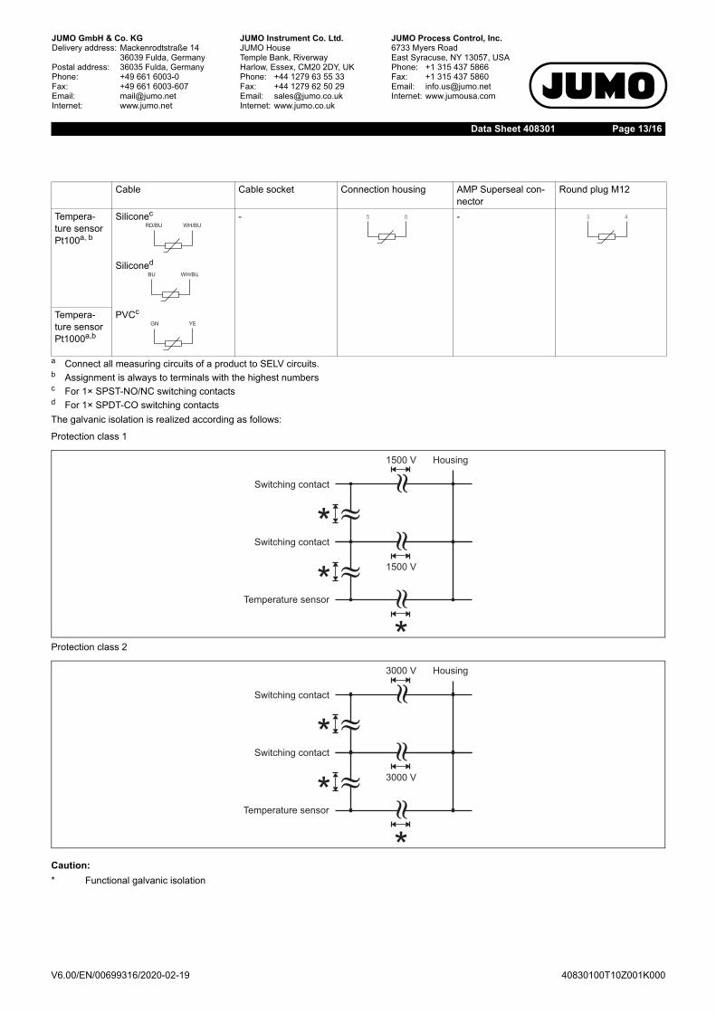
The galvanic isolation is realized according as follows:
Protection class 1
Protection class 2
Cable Cable socket Connection housing AMP Superseal con-nector
Round plug M12
Tempera-ture sensor Pt100a, b
Siliconec - -
Siliconed
Tempera-ture sensor Pt1000a,b
PVCc
a Connect all measuring circuits of a product to SELV circuits.b Assignment is always to terminals with the highest numbersc For 1× SPST-NO/NC switching contactsd For 1× SPDT-CO switching contacts
Caution:* Functional galvanic isolation

V6.00/EN/00699316/2020-02-19
Page 14/16Data Sheet 408301
40830100T10Z001K000
If connected to a certified intrinsically safe electrical circuit Ex i, the following maximum values are admissible.
When using explosion-proof versions (intrinsically safe, Ex i, and flameproof enclosure, Ex d) the following values are given.
Connection examples of versions with explosion protectionFloat switch (S)
Contact function Max. voltage Ui
Max. current Ui Max. power Pi
Internal inductance
Internal capacitance
in V in mA in mW in µH in pFSPST-NO ≤ 30 ≤ 100 ≤ 750 ~0
for cable version 1 µH/m connecting cable
~0for cable version 200 pF/mconnecting cable
SPST-NCSPDT-CO
Contact function Max. voltage Ui
Max. current Ui Max. power Pi
Internal inductance
Internal capacitance
in V in mA in mW in µH in pFPt100 ≤ 30 ≤ 55 ≤ 413 ~0
for cable version 1 µH/m connecting cable
~0for cable version 200 pF/mconnecting cable
Pt1000
Legend: cable BN Brown GN GreenWH White RD RedBU Blue YE YellowPK Pink GY Grey
Ex i Ex dEx-i isolating switch amplifier According to operating manual 408301, chapter 6 on "Installation", the
fuse (F) must be selected.
e.g. AC 230 V
e.g. AC/DC 24 to 230 V
S
IN OUT
V6.00/EN/00699316/2020-02-19
Page 15/16Data Sheet 408301
40830100T10Z001K000
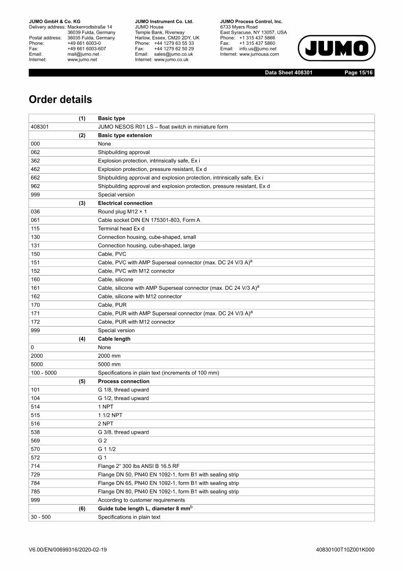
Order details(1) Basic type
408301 JUMO NESOS R01 LS – float switch in miniature form(2) Basic type extension
000 None062 Shipbuilding approval362 Explosion protection, intrinsically safe, Ex i462 Explosion protection, pressure resistant, Ex d662 Shipbuilding approval and explosion protection, intrinsically safe, Ex i962 Shipbuilding approval and explosion protection, pressure resistant, Ex d999 Special version
(3) Electrical connection036 Round plug M12 × 1061 Cable socket DIN EN 175301-803, Form A115 Terminal head Ex d130 Connection housing, cube-shaped, small131 Connection housing, cube-shaped, large150 Cable, PVC151 Cable, PVC with AMP Superseal connector (max. DC 24 V/3 A)a
152 Cable, PVC with M12 connector160 Cable, silicone161 Cable, silicone with AMP Superseal connector (max. DC 24 V/3 A)a
162 Cable, silicone with M12 connector170 Cable, PUR171 Cable, PUR with AMP Superseal connector (max. DC 24 V/3 A)a
172 Cable, PUR with M12 connector999 Special version
(4) Cable length0 None2000 2000 mm5000 5000 mm100 - 5000 Specifications in plain text (increments of 100 mm)
(5) Process connection101 G 1/8, thread upward104 G 1/2, thread upward514 1 NPT515 1 1/2 NPT516 2 NPT538 G 3/8, thread upward569 G 2570 G 1 1/2572 G 1714 Flange 2“ 300 lbs ANSI B 16.5 RF729 Flange DN 50, PN40 EN 1092-1, form B1 with sealing strip784 Flange DN 65, PN40 EN 1092-1, form B1 with sealing strip785 Flange DN 80, PN40 EN 1092-1, form B1 with sealing strip999 According to customer requirements
(6) Guide tube length L, diameter 8 mmb
30 - 500 Specifications in plain text

V6.00/EN/00699316/2020-02-19
Page 16/16Data Sheet 408301
40830100T10Z001K000
(7) Float027 Cylinder, CrNi (stainless steel), diameter 27, density 800 kg/m3
029 Spherical, CrNi (stainless steel), diameter 29, density 900 kg/m3
729 Spherical, Ti (titanium), diameter 29, density 700 kg/m3
(8) Number of floats1 1 piece2 2 pieces3 3 pieces4 4 pieces
(9) Switching function01 SPST-NO, N/O contact (10 W/DC 175 V/0.5 A)02 SPST-NC, N/C contact (10 W/DC 175 V/0.5 A)03 SPDT-CO, single-pole changeover contact (10 W/DC 175 V/0.5 A)10 SPST-NO, N/O contact (100 W/DC 230 V/1 A)15 SPST-NO, N/O contact, bistable (100 W/DC 230 V/1 A)
(10) Number of contactsc
1 1 contact2 2 contacts3 3 contacts4 4 contacts
(11) Position of contact 1c
20 - 470 Specifications in plain text(12) Position of contact 2c
0 None20 - 470 Specifications in plain text
(13) Position of contact 3c
0 None40 - 470 Specifications in plain text
(14) Position of contact 4c
0 None40 - 470 Specifications in plain text
(15) Extra codes000 None005 Integrated temperature sensor Pt1000d
007 Integrated temperature sensor Pt100d
019 Temperature monitoring of reed contact, Pt1000370 Extension tube
a Not available with shipbuilding approval (basic type extension 062), shipbuilding approval and explosion protection, intrinsically safe, Ex i (basictype extension 662) and shipbuilding approval and explosion protection, pressure resistant, Ex d (basic type extension 962).
b The dimensioning is in mm in relation to the contact/reference surface (threaded bushing of the container/tank wall) of the selected processconnection (for details see operating manual, chapter 3.2).
c The contact positions are observed from the process connection toward the guide tube end (for details see operating manual, chapter 3.2).d The temperature sensor is positioned at the end of the guide tube.
(1) (2) (3) (4) (5) (6) (7) (8)Order code / - - - - - - -Order example 408301 / 000 - 160 - 1000 - 101 - 47 - 027 - 1 -
(9) (10) (11) (12) (13) (14) (15)- - - - - /
10 - 1 - 23 - 0 - 0 - 0 / 000
Minimum order volume: 1 piece