jyri€pakarinen,€tapio€puputti,€and€vesa€välimäki,€2008
TRANSCRIPT

Jyri Pakarinen, Tapio Puputti, and Vesa Välimäki, 2008, Virtual slide guitar, ComputerMusic Journal, volume 32, number 3, pages 4254.
© 2008 MIT Press
Reprinted with permission.
Virtual Slide GuitarJyri Pakarinen, Tapio Puputti,and Vesa ValimakiHelsinki University of TechnologyDepartment of SignalProcessing and AcousticsP.O. Box 3000FI-02015 TKK Finland{jyri.pakarinen, tapio.puputti,vesa.valimaki}@tkk.fi
This article describes a system for virtual slideguitar playing. From the control point of view,it can be seen as a successor of the virtual airguitar (VAG) developed at Helsinki University ofTechnology (TKK) a few years ago (Karjalainenet al. 2006). The original VAG allows the user tocontrol an electric guitar synthesizer by mimickingguitar-playing gestures. In the current work, thesame gesture-control approach that was foundsuccessful in the VAG is used: a computer-vision-based system, in which a camera detects the player’shands and a computer tracks the hand movementsand converts them into control data, such as pluckevents and string length. Sound synthesis in thevirtual slide guitar application is based on anenergy-compensated time-varying digital waveguidemodel of a guitar with new extensions to generatecontact sounds caused by the slide tube touching thestrings. Video files showing the virtual slide guitar inaction can be found on the accompanying Web page(www.acoustics.hut.fi/publications/papers/vsg/)and the forthcoming 2008 Computer Music JournalSound and Video Anthology DVD. Although thecurrent implementation uses a camera-based userinterface, it can also be controlled by other human–machine interfaces or computer programs.
Excellent reviews on gestural control of musicsynthesis have been written by Paradiso (1997) andby Wanderley and Depalle (2004). Camera-based ges-ture analysis has become very sophisticated owing toincreased computing power and new methodologiesprovided by research, as exemplified by the EyesWebplatform (Camurri et al. 2000, 2005; Gormanet al. 2007). Digital waveguide modeling is maturetechnology, which can be applied to high-qualitysynthesis of various musical instruments (Smith1992; Valimaki et al. 2006). For more information
Computer Music Journal, 32:3, pp. 42–54, Fall 2008c© 2008 Massachusetts Institute of Technology.
on waveguide synthesis of string instruments, seeValimaki et al. (1996), Karjalainen, Valimaki, andTolonen (1998), and Karjalainen et al. (2006).
The roots of this study are in an early proto-type of the TKK virtual air guitar, which here iscalled the rubber-band virtual air guitar. It was asimplified gesture-control system, in which thedistance between the hands was detected and di-rectly converted to string length. The string lengthwas updated frequently enough to be practicallyinstantaneously dependent on hand locations. Therubber-band VAG was entertaining for a short time,but it was not a practical musical instrument: Therewas a noticeable latency between a pluck and theresulting sound, pitch changes occurred too effort-lessly, and it was practically impossible to maintaina constant pitch. As a consequence, a rubber-bandVAG player generated glissandi up and down ortones with shaky pitch but could not play a singlemelody. In the advanced versions of the VAG, thedistance between hands is quantized so that a regionof several centimeters in the air corresponds to aconstant pitch or a single chord (Karjalainen et al.2006). Although such a restriction decreases theexpressive range, it also enables the user to learnplay simple melodies and chords with this invisibleinstrument.
The authors realized that the rubber-band VAGcontroller could be used for controlling slide-guitarsynthesis. The term slide guitar or bottleneck guitarrefers to a specific traditional playing technique on asteel-string acoustic or electric guitar. When playingthe slide guitar, the musician wears a slide tube onthe fretting hand. Figure 1 illustrates this.
Instead of pressing the strings against the fret-board, the player glides the tube on the strings whilethe picking hand plucks the strings in a regular fash-ion. This produces a unique, voice-like tone withstepless pitch control. Although the tube is usuallyslid along all six strings, single-note melodies can
42 Computer Music Journal

Figure 1. When playing theslide guitar, the musicianwears a slide tube on thefretting hand.
be played by plucking just one string and dampingthe others with the picking hand. The slide tube—usually made of glass or metal—also generates asqueaking sound while moving along on the woundmetal strings. In most cases, the slide guitar istuned into an open tuning (for example the open Gtuning: D2, G2, D3, G3, B3, and D4 starting fromthe thickest string). This allows the user to playsimple chords just by sliding the tube into differentpositions on the guitar neck. The player usuallywears the slide tube on the little or ring finger (seeFigure 1), and the other fingers are free to fret thestrings normally. For an example of slide-guitarplaying, refer to Johnson (1990).
In slide-guitar playing, the user gets continuousauditory feedback of the hand movements, andthis helps the regulation of hand movements andpitch control in the virtual slide-guitar application.The present article and the related videos (onthe forthcoming DVD) show that this leads to afunctional application, the virtual slide guitar (VSG).
Slide Guitar Sound Analysis
The unique, characteristic sound of the slide guitaris mostly due to the continuous change in pitch.Typically, the player plucks a string while simul-taneously damping out any vibrations in the otherstrings. Next, the player slides the tube to a newposition on the guitar neck, thus continuously
changing the pitch. After reaching the target pitch,a vibrato is usually applied by sliding the tube backand forth. Owing to the excessive use of vibrato,constant-pitched tones are usually only those thatare played on the open strings, namely, strings nottouched by the tube. The sliding tube-string contactexcites both string segments, the one between thebridge and the tube, and the one between the tubeand the nut. The latter segment is often, however,damped with the free fingers of the tube hand.
Contact Sounds
The sliding contact point between the string and theslide tube produces noise. The type of this contactsound depends not only on the tube material, butalso on the construction of the strings. Woundstrings (i.e., strings where another string is wrappedaround a core string) tend to produce a squeakysound, whereas plain strings produce a quiet, hiss-like noise. The contact noise type also varies withthe sliding movement: Fast slides produce loudercontact noise with more emphasis on the highfrequencies than do slow slides.
Figure 2 shows spectrogram images of four differ-ent slide events conducted on a steel-string acousticguitar. These slides were performed by simply mov-ing the tube from one position to another on a singlestring, without any special attempt for maintaining aconstant slide velocity. The recordings were made inthe small anechoic chamber at Helsinki Universityof Technology using a microphone (AKG C 480 B)placed 1 m away from the instrument and directed atthe sound hole. The signals were recorded digitally(44,100-Hz sampling rate, 16 bits) using a Yamaha01V digital mixer and then fed into a PC laptop viaa Digigram VX Pocket soundcard. In Figure 2a, theslide was performed with a brass tube on the woundsixth string. In Figure 2b, a glass tube was slid on thesame sixth string. Figures 2c and 2d illustrate theslides of a brass and glass tube, respectively, onthe wound fifth string. In all cases, the string wasdamped on both sides of the tube so that the transver-sal string vibrations were heavily attenuated.
Generally, the contact sound between the tubeand the wound strings is caused by the same
Pakarinen, Puputti, and Valimaki 43
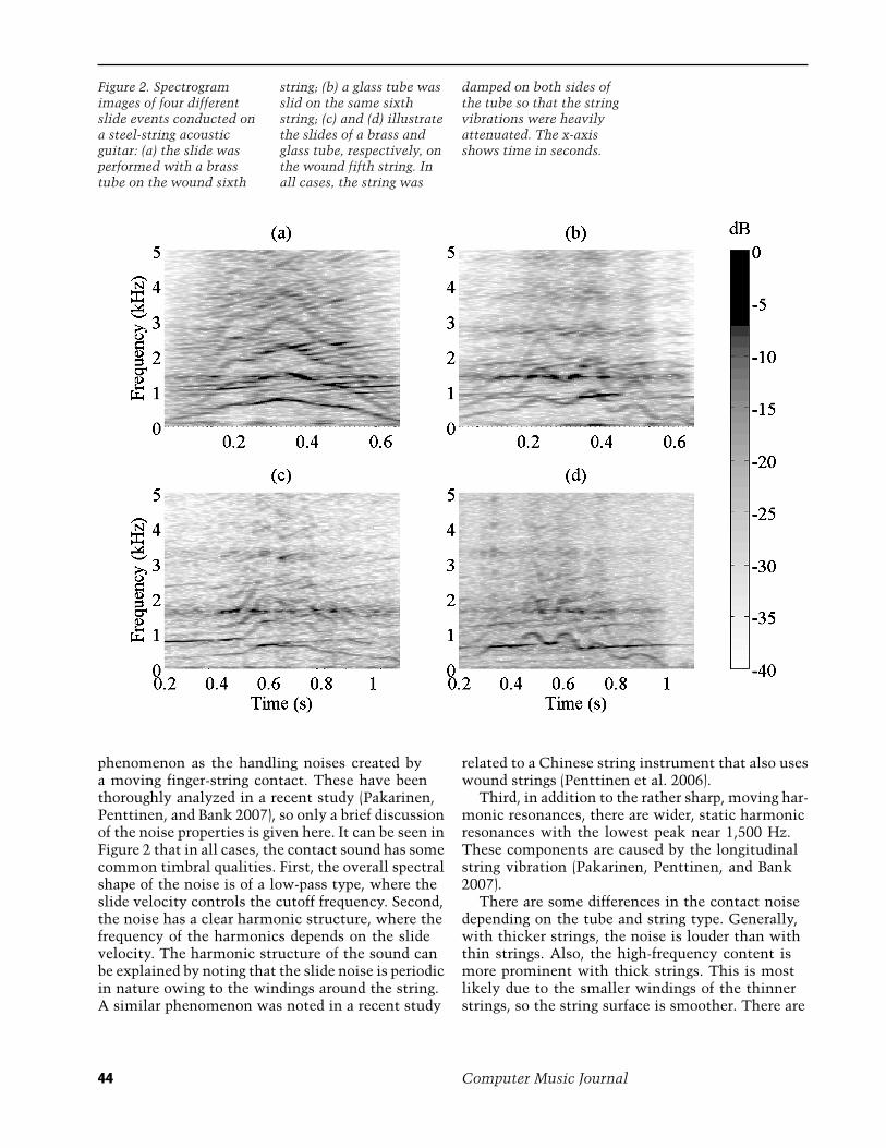
Figure 2. Spectrogramimages of four differentslide events conducted ona steel-string acousticguitar: (a) the slide wasperformed with a brasstube on the wound sixth
string; (b) a glass tube wasslid on the same sixthstring; (c) and (d) illustratethe slides of a brass andglass tube, respectively, onthe wound fifth string. Inall cases, the string was
damped on both sides ofthe tube so that the stringvibrations were heavilyattenuated. The x-axisshows time in seconds.
phenomenon as the handling noises created bya moving finger-string contact. These have beenthoroughly analyzed in a recent study (Pakarinen,Penttinen, and Bank 2007), so only a brief discussionof the noise properties is given here. It can be seen inFigure 2 that in all cases, the contact sound has somecommon timbral qualities. First, the overall spectralshape of the noise is of a low-pass type, where theslide velocity controls the cutoff frequency. Second,the noise has a clear harmonic structure, where thefrequency of the harmonics depends on the slidevelocity. The harmonic structure of the sound canbe explained by noting that the slide noise is periodicin nature owing to the windings around the string.A similar phenomenon was noted in a recent study
related to a Chinese string instrument that also useswound strings (Penttinen et al. 2006).
Third, in addition to the rather sharp, moving har-monic resonances, there are wider, static harmonicresonances with the lowest peak near 1,500 Hz.These components are caused by the longitudinalstring vibration (Pakarinen, Penttinen, and Bank2007).
There are some differences in the contact noisedepending on the tube and string type. Generally,with thicker strings, the noise is louder than withthin strings. Also, the high-frequency content ismore prominent with thick strings. This is mostlikely due to the smaller windings of the thinnerstrings, so the string surface is smoother. There are
44 Computer Music Journal
2 4 6 8 10 12 14 16 18 20 22
0
Frequency (kHz)
Mag
nitu
de (
dB)
GlassBrass
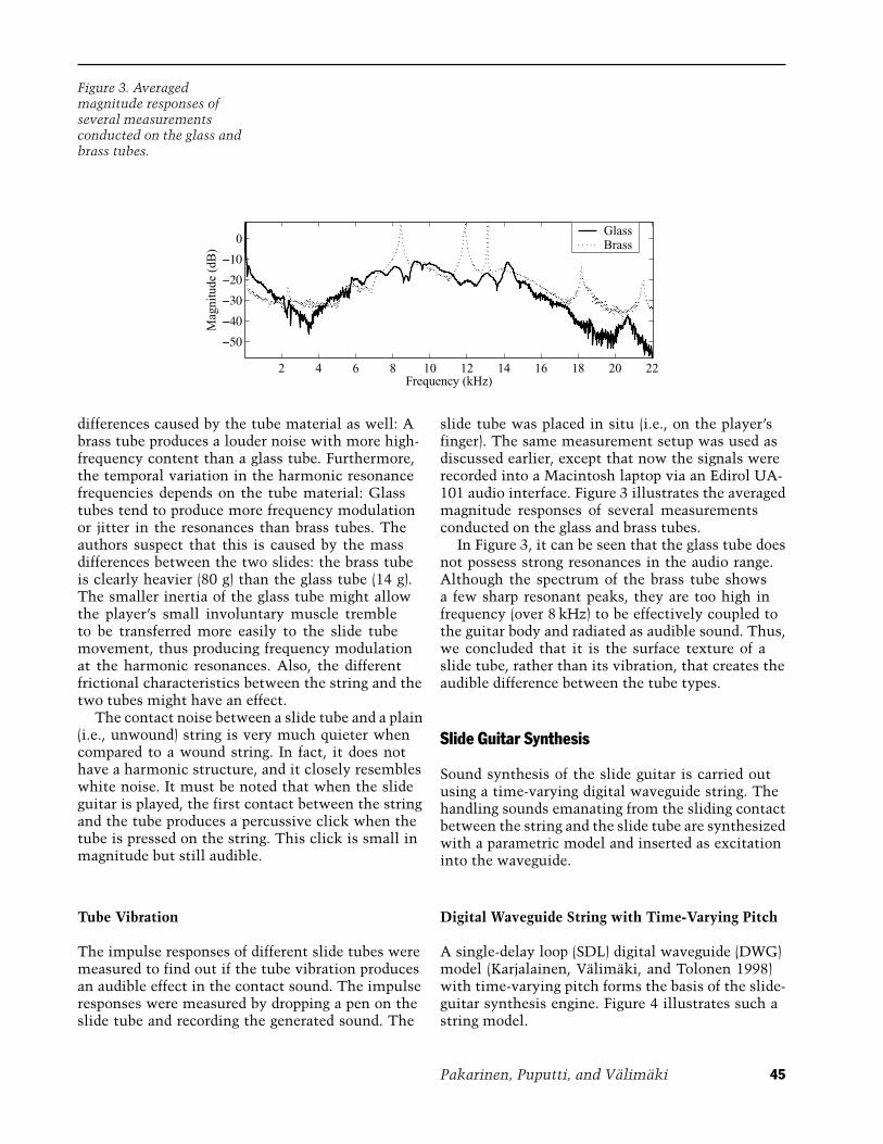
Figure 3. Averagedmagnitude responses ofseveral measurementsconducted on the glass andbrass tubes.
differences caused by the tube material as well: Abrass tube produces a louder noise with more high-frequency content than a glass tube. Furthermore,the temporal variation in the harmonic resonancefrequencies depends on the tube material: Glasstubes tend to produce more frequency modulationor jitter in the resonances than brass tubes. Theauthors suspect that this is caused by the massdifferences between the two slides: the brass tubeis clearly heavier (80 g) than the glass tube (14 g).The smaller inertia of the glass tube might allowthe player’s small involuntary muscle trembleto be transferred more easily to the slide tubemovement, thus producing frequency modulationat the harmonic resonances. Also, the differentfrictional characteristics between the string and thetwo tubes might have an effect.
The contact noise between a slide tube and a plain(i.e., unwound) string is very much quieter whencompared to a wound string. In fact, it does nothave a harmonic structure, and it closely resembleswhite noise. It must be noted that when the slideguitar is played, the first contact between the stringand the tube produces a percussive click when thetube is pressed on the string. This click is small inmagnitude but still audible.
Tube Vibration
The impulse responses of different slide tubes weremeasured to find out if the tube vibration producesan audible effect in the contact sound. The impulseresponses were measured by dropping a pen on theslide tube and recording the generated sound. The
slide tube was placed in situ (i.e., on the player’sfinger). The same measurement setup was used asdiscussed earlier, except that now the signals wererecorded into a Macintosh laptop via an Edirol UA-101 audio interface. Figure 3 illustrates the averagedmagnitude responses of several measurementsconducted on the glass and brass tubes.
In Figure 3, it can be seen that the glass tube doesnot possess strong resonances in the audio range.Although the spectrum of the brass tube showsa few sharp resonant peaks, they are too high infrequency (over 8 kHz) to be effectively coupled tothe guitar body and radiated as audible sound. Thus,we concluded that it is the surface texture of aslide tube, rather than its vibration, that creates theaudible difference between the tube types.
Slide Guitar Synthesis
Sound synthesis of the slide guitar is carried outusing a time-varying digital waveguide string. Thehandling sounds emanating from the sliding contactbetween the string and the slide tube are synthesizedwith a parametric model and inserted as excitationinto the waveguide.
Digital Waveguide String with Time-Varying Pitch
A single-delay loop (SDL) digital waveguide (DWG)model (Karjalainen, Valimaki, and Tolonen 1998)with time-varying pitch forms the basis of the slide-guitar synthesis engine. Figure 4 illustrates such astring model.
Pakarinen, Puputti, and Valimaki 45

y(n)x(n)
-LIzHl(z)
-Lfz
Integer delayFractionaldelay
Loop filter
Figure 4. Single-delay loopdigital waveguide model(Karjalainen, Valimaki,and Tolonen 1998) withtime-varying pitch formsthe basis of the slide-guitarsynthesis engine.
The waveguide consists of a simple integerdelay loop with two additional filters: one forimplementing the fractional part of the delay, andthe other (referred to here as the “loop filter”) forsimulating the vibrational losses in the string. Notethat both the integer delay line length and thefractional delay filter are time-varying: The usercontrols the total loop delay value—and thus alsothe pitch—during run time.
The fractional delay filter allows for a smoothtransition between pitches and also enables thecorrect tuning of the string. There are severaltechniques for implementing fractional delay filters,a thorough tutorial being found in Laakso et al.(1996). For the purpose of this work, a fifth-orderLagrange interpolator was found to work sufficientlywell. It must be noted that, because the interpolationaccuracy of a fractional delay filter is highest near themidpoint of the filter (e.g., near delay value 2.5 for a6-tap filter), this fifth-order Lagrange interpolator isoperated in the delay range from 2.0 to 3.0 samples,and the constant two-sample overhead delay dueto the Lagrange interpolator is compensated in theinteger delay line by making it two samples shorter.
For the loop filter, a one-pole lowpass filter[Hl(z) = g(1 + a)/(1 + az−1) with cutoff parameter aand gain g] is used with approximated polynomialparameters depending on the length and type of thestring, as suggested in Valimaki and Tolonen (1998).
Energy Compensation
When changing the length of a DWG string duringrun time, the signal energy is varied (Pakarinen et al.2005). For example, if the DWG string is suddenlyshortened to half of its original length, half of thesignal samples are discarded, and approximately50 percent of the signal energy is lost. In practice,
this can be heard as an unnaturally quick decay ofthe string sound. While the true energetic behaviorof an actual physical string with time-varying lengthmight be controversial, one can safely assumethat this type of artificial energy change owingto the DWG implementation is non-physical, andwe must therefore compensate for it. Two energy-compensation methods are presented by Pakarinenet al. (2005), from which the computationallysimpler energy scaling method, the zero-orderenergy-preserving interpolation, which adds a singletime-varying scaling coefficient into the SDL, waschosen.
The basic difficulty with energy compensationin time-varying strings is that when the lengthof the DWG string changes, an estimate for theadditional loss or gain of energy would be needed.Obviously, this requires an estimate for the signalvalues in the lost or gained delay line segment.In the zero-order energy-preserving interpolation,a constant signal value is assumed for this delaysegment, and, as noted by Pakarinen et al. (2005),the scaling operation can be expressed as
pc(n) =√
1 − �xp(n) = gc p(n) (1)
Here, n is the time index, p(n) is the signal outputfrom the time-varying delay block, pc(n) is theenergy-compensated signal, gc is the scaling coeffi-cient, and �x is the delay-line variation in samplesper one time step. The zero-order energy-preservinginterpolation is accurate only when the string’slength does not change too rapidly compared to thewavelength λ:
|�x| � λ (2)
Assume that a quick slide with open G tuning isperformed from the second fret on the sixth string(E2 = 82.4 Hz = f1) one octave up to the 14th fret(E3 = 164.81 Hz = f2), and it takes time �t = 0.5sec. Now, the absolute value of the delay line lengthchange per time step will be
|�x| = 12�t
(1f2
− 1f1
)(3)
which equals 0.0061 for the frequencies chosenhere. For a given frequency f , the wavelength on a
46 Computer Music Journal
Wound string
Slide tube
Time
Am
plit
ude
Noise pulse
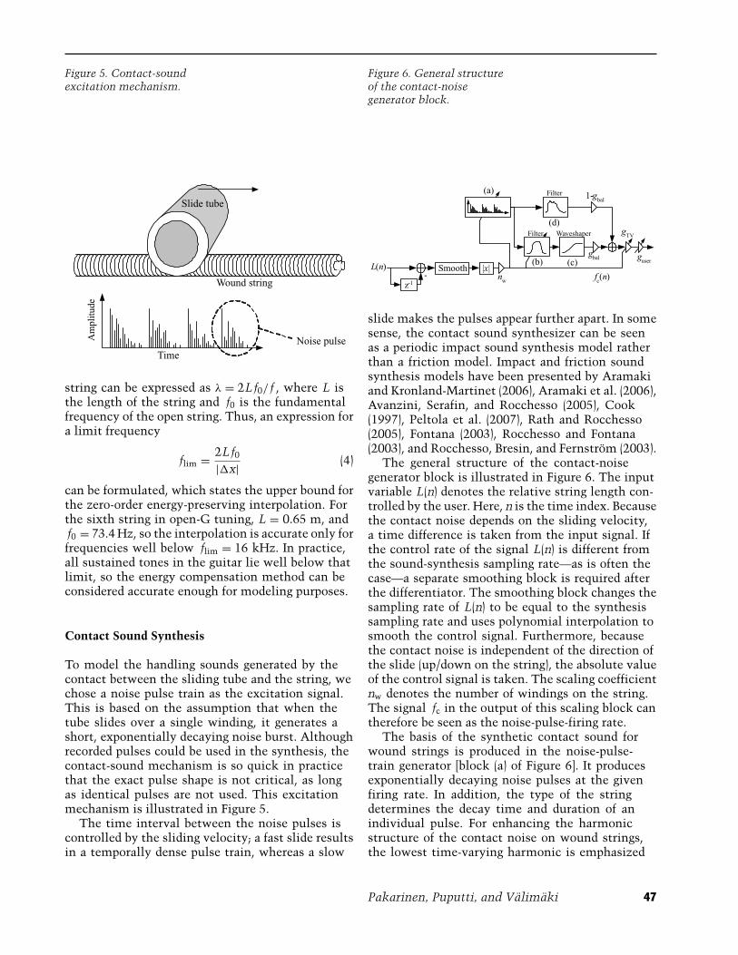
Figure 5. Contact-soundexcitation mechanism.
string can be expressed as λ = 2Lf0/ f , where L isthe length of the string and f0 is the fundamentalfrequency of the open string. Thus, an expression fora limit frequency
flim = 2Lf0
|�x| (4)
can be formulated, which states the upper bound forthe zero-order energy-preserving interpolation. Forthe sixth string in open-G tuning, L = 0.65 m, andf0 = 73.4 Hz, so the interpolation is accurate only forfrequencies well below flim = 16 kHz. In practice,all sustained tones in the guitar lie well below thatlimit, so the energy compensation method can beconsidered accurate enough for modeling purposes.
Contact Sound Synthesis
To model the handling sounds generated by thecontact between the sliding tube and the string, wechose a noise pulse train as the excitation signal.This is based on the assumption that when thetube slides over a single winding, it generates ashort, exponentially decaying noise burst. Althoughrecorded pulses could be used in the synthesis, thecontact-sound mechanism is so quick in practicethat the exact pulse shape is not critical, as longas identical pulses are not used. This excitationmechanism is illustrated in Figure 5.
The time interval between the noise pulses iscontrolled by the sliding velocity; a fast slide resultsin a temporally dense pulse train, whereas a slow
L(n)
z-1
Smooth |x|
(a)
(b) (c)
(d)
- nw
gbal
1-gbal
guser
gTV
fc(n)
Filter
Filter Waveshaper
Figure 6. General structureof the contact-noisegenerator block.
slide makes the pulses appear further apart. In somesense, the contact sound synthesizer can be seenas a periodic impact sound synthesis model ratherthan a friction model. Impact and friction soundsynthesis models have been presented by Aramakiand Kronland-Martinet (2006), Aramaki et al. (2006),Avanzini, Serafin, and Rocchesso (2005), Cook(1997), Peltola et al. (2007), Rath and Rocchesso(2005), Fontana (2003), Rocchesso and Fontana(2003), and Rocchesso, Bresin, and Fernstrom (2003).
The general structure of the contact-noisegenerator block is illustrated in Figure 6. The inputvariable L(n) denotes the relative string length con-trolled by the user. Here, n is the time index. Becausethe contact noise depends on the sliding velocity,a time difference is taken from the input signal. Ifthe control rate of the signal L(n) is different fromthe sound-synthesis sampling rate—as is often thecase—a separate smoothing block is required afterthe differentiator. The smoothing block changes thesampling rate of L(n) to be equal to the synthesissampling rate and uses polynomial interpolation tosmooth the control signal. Furthermore, becausethe contact noise is independent of the direction ofthe slide (up/down on the string), the absolute valueof the control signal is taken. The scaling coefficientnw denotes the number of windings on the string.The signal fc in the output of this scaling block cantherefore be seen as the noise-pulse-firing rate.
The basis of the synthetic contact sound forwound strings is produced in the noise-pulse-train generator [block (a) of Figure 6]. It producesexponentially decaying noise pulses at the givenfiring rate. In addition, the type of the stringdetermines the decay time and duration of anindividual pulse. For enhancing the harmonicstructure of the contact noise on wound strings,the lowest time-varying harmonic is emphasized
Pakarinen, Puputti, and Valimaki 47
30
20
10
0
Brass slideM
agni
tude
(dB
)
String #6
Glass slide
String #6
Chromed slide
String #6
30
20
10
0
Mag
nitu
de (
dB)
String #5 String #5 String #5
0.5 1 2 3 4 5
30
20
10
0
String #4Mag
nitu
de (
dB)
Frequency (kHz)0.5 1 2 3 4 5
String #4
Frequency (kHz)0.5 1 2 3 4 5
String #4
Frequency (kHz)
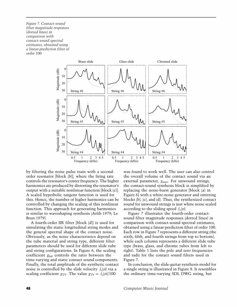
Figure 7. Contact-soundfilter magnitude responses(dotted lines) incomparison withcontact-sound spectralestimates, obtained usinga linear-prediction filter oforder 100.
by filtering the noise pulse train with a second-order resonator [block (b)], where the firing ratecontrols the resonator’s center frequency. The higherharmonics are produced by distorting the resonator’soutput with a suitable nonlinear function [block (c)].A scaled hyperbolic tangent function is used forthis. Hence, the number of higher harmonics can becontrolled by changing the scaling of this nonlinearfunction. This approach for generating harmonicsis similar to waveshaping synthesis (Arfib 1979; LeBrun 1979).
A fourth-order IIR filter [block (d)] is used forsimulating the static longitudinal string modes andthe general spectral shape of the contact noise.Obviously, as the noise characteristics depend onthe tube material and string type, different filterparameters should be used for different slide tubeand string configurations. In Figure 6, the scalingcoefficient gbal controls the ratio between thetime-varying and static contact sound components.Finally, the total amplitude of the synthetic contactnoise is controlled by the slide velocity fc(n) via ascaling coefficient gTV. The value gTV = fc(n)/100
was found to work well. The user can also controlthe overall volume of the contact sound via anexternal parameter, guser. For unwound strings,the contact-sound synthesis block is simplified byreplacing the noise-burst generator [block (a) inFigure 6] with a white-noise generator and omittingblocks (b), (c), and (d). Thus, the synthesized contactsound for unwound strings is just white noise scaledaccording to the sliding speed fc(n).
Figure 7 illustrates the fourth-order contact-sound filter magnitude responses (dotted lines) incomparison with contact-sound spectral estimates,obtained using a linear-prediction filter of order 100.Each row in Figure 7 represents a different string (thesixth, fifth, and fourth strings from top to bottom),while each column represents a different slide tubetype (brass, glass, and chrome tubes from left toright). Table 1 lists the pole and zero frequenciesand radii for the contact sound filters used inFigure 7.
In conclusion, the slide-guitar synthesis model fora single string is illustrated in Figure 8. It resemblesthe ordinary time-varying SDL DWG string, but
48 Computer Music Journal
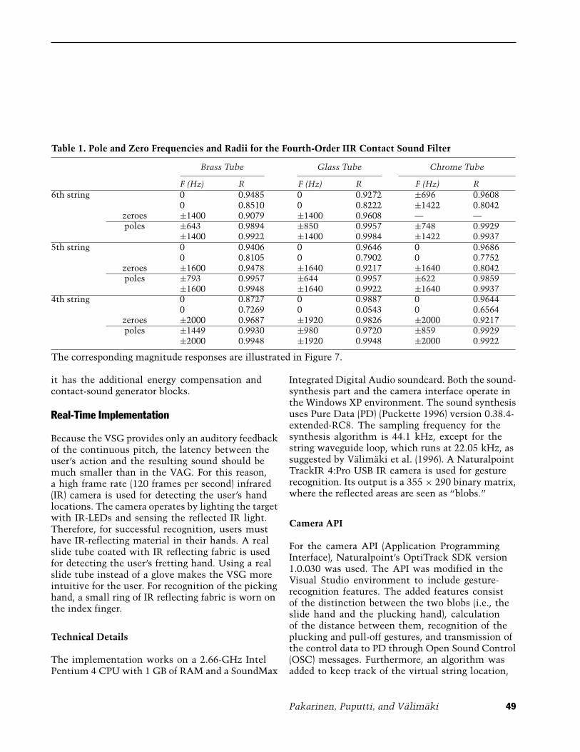
Table 1. Pole and Zero Frequencies and Radii for the Fourth-Order IIR Contact Sound Filter
Brass Tube Glass Tube Chrome Tube
F (Hz) R F (Hz) R F (Hz) R6th string 0 0.9485 0 0.9272 ±696 0.9608
0 0.8510 0 0.8222 ±1422 0.8042zeroes ±1400 0.9079 ±1400 0.9608 — —poles ±643 0.9894 ±850 0.9957 ±748 0.9929
±1400 0.9922 ±1400 0.9984 ±1422 0.99375th string 0 0.9406 0 0.9646 0 0.9686
0 0.8105 0 0.7902 0 0.7752zeroes ±1600 0.9478 ±1640 0.9217 ±1640 0.8042poles ±793 0.9957 ±644 0.9957 ±622 0.9859
±1600 0.9948 ±1640 0.9922 ±1640 0.99374th string 0 0.8727 0 0.9887 0 0.9644
0 0.7269 0 0.0543 0 0.6564zeroes ±2000 0.9687 ±1920 0.9826 ±2000 0.9217poles ±1449 0.9930 ±980 0.9720 ±859 0.9929
±2000 0.9948 ±1920 0.9948 ±2000 0.9922
The corresponding magnitude responses are illustrated in Figure 7.
it has the additional energy compensation andcontact-sound generator blocks.
Real-Time Implementation
Because the VSG provides only an auditory feedbackof the continuous pitch, the latency between theuser’s action and the resulting sound should bemuch smaller than in the VAG. For this reason,a high frame rate (120 frames per second) infrared(IR) camera is used for detecting the user’s handlocations. The camera operates by lighting the targetwith IR-LEDs and sensing the reflected IR light.Therefore, for successful recognition, users musthave IR-reflecting material in their hands. A realslide tube coated with IR reflecting fabric is usedfor detecting the user’s fretting hand. Using a realslide tube instead of a glove makes the VSG moreintuitive for the user. For recognition of the pickinghand, a small ring of IR reflecting fabric is worn onthe index finger.
Technical Details
The implementation works on a 2.66-GHz IntelPentium 4 CPU with 1 GB of RAM and a SoundMax
Integrated Digital Audio soundcard. Both the sound-synthesis part and the camera interface operate inthe Windows XP environment. The sound synthesisuses Pure Data (PD) (Puckette 1996) version 0.38.4-extended-RC8. The sampling frequency for thesynthesis algorithm is 44.1 kHz, except for thestring waveguide loop, which runs at 22.05 kHz, assuggested by Valimaki et al. (1996). A NaturalpointTrackIR 4:Pro USB IR camera is used for gesturerecognition. Its output is a 355 × 290 binary matrix,where the reflected areas are seen as “blobs.”
Camera API
For the camera API (Application ProgrammingInterface), Naturalpoint’s OptiTrack SDK version1.0.030 was used. The API was modified in theVisual Studio environment to include gesture-recognition features. The added features consistof the distinction between the two blobs (i.e., theslide hand and the plucking hand), calculationof the distance between them, recognition of theplucking and pull-off gestures, and transmission ofthe control data to PD through Open Sound Control(OSC) messages. Furthermore, an algorithm wasadded to keep track of the virtual string location,
Pakarinen, Puputti, and Valimaki 49

y(n)x(n)
-LIzHl(z) -L fz
Integer delayFractionaldelay
Loop filter Energycompensation
CSG
Contact soundgenerator
gc
Figure 8. Slide-guitarsynthesis model for asingle string.
that is, an imaginary line representing the virtualstring. This is similar to the work presented byKarjalainen et al. (2006). The line is drawn throughthe tube and the averaged location of the pluckinghand, so that the virtual string slowly follows theplayer’s movements. The API detects the directionof the plucking hand movement, and when thevirtual string is crossed, a pluck event and a directionparameter is sent. Also, a minimum-velocity limit isdefined for the plucking gesture to avoid false plucks.
For more realistic playing, a pull-off-feature hasbeen added to the system. This means that the APIswitches the string length to maximum wheneverthe slide hand is opened. When the slide hand isclosed, the string length is again set according to thedistance between the user’s hands. Thus, the usercan lift the slide tube off the virtual strings, pluckopen strings, and then press the tube on the stringsagain. This is idiomatic for slide-guitar playing.Opening the slide hand makes the tube finger pointto the camera such that the slide tube vanishes fromthe IR camera’s view. When the tube is missing, thecoordinates where the tube was last seen are usedfor setting the string’s location. In this way, openstrings can also be plucked.
Because the slide tube and the fabric ring havequite different shapes, it is easy for the system todistinguish between them. In practice, this is doneby selecting the more square-like blob as the ring andthe longitudinal blob as the tube. This allows the in-strument to be played by left-handed people as well.
System Calibration and PD Implementation
The system is calibrated so that the distance of250 pixels corresponds to 48 cm when playedapproximately 2 m away from the camera. The
distance is constrained in such a way that moving thehands further apart than 250 pixels does not makethe strings any longer but will map them as openstrings. Similarly, the minimum distance betweenthe user’s hands is constrained to 62.5 pixels (12 cmwhen played 2 m away), thus leading to a playingpitch range of an octave and a minor third for eachstring (from open string to the 15th fret). Becausethe plucking hand is not normally positioned at thebridge of the guitar but near the sound hole, an offsetof 17 cm is added to the distance to obtain the totallength of the strings (65 cm for open strings). Next,the distance between the hands is normalized bydividing it with the open string length. This resultsin a relative string length [L(n) in Figure 6] between0.446 and 1.0. Because typical use of a slide tubemakes every string have the same playing length,this normalized string length is used as a controlsignal for each of the synthesized strings.
When the PD implementation receives an OSCmessage containing a pluck event, an excitationsignal is inserted into each waveguide string. Theexcitation signal is a short noise burst simulating astring pluck. There is also a slight delay (20 msec)between different string excitations for creatinga more realistic “strumming” feel. The order inwhich the strings are plucked depends on theplucking direction.
Figure 9 illustrates the PD implementation of theuser interface. The overall latency of PD is about20 msec using ASIO (Audio Stream In/Out) sounddrivers. For additional effects, VST (Virtual StudioTechnology) plug-ins can be used with PD, but theywill naturally add to the computational load of thesystem. The PD implementation can produce thesound as it is, through a reverb effect (modified fromPD audio examples), or through a FreeAmp2 VSTplug-in (available online at frettedsynth.asseca.com).
50 Computer Music Journal
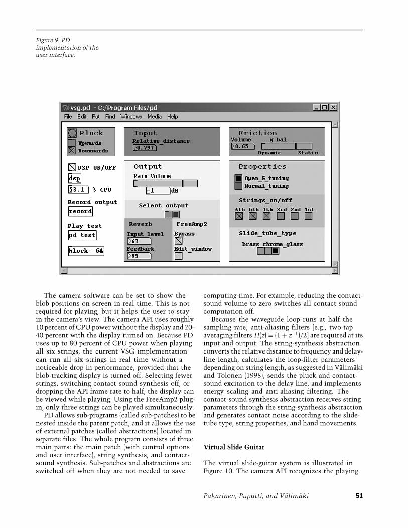
Figure 9. PDimplementation of theuser interface.
The camera software can be set to show theblob positions on screen in real time. This is notrequired for playing, but it helps the user to stayin the camera’s view. The camera API uses roughly10 percent of CPU power without the display and 20–40 percent with the display turned on. Because PDuses up to 80 percent of CPU power when playingall six strings, the current VSG implementationcan run all six strings in real time without anoticeable drop in performance, provided that theblob-tracking display is turned off. Selecting fewerstrings, switching contact sound synthesis off, ordropping the API frame rate to half, the display canbe viewed while playing. Using the FreeAmp2 plug-in, only three strings can be played simultaneously.
PD allows sub-programs (called sub-patches) to benested inside the parent patch, and it allows the useof external patches (called abstractions) located inseparate files. The whole program consists of threemain parts: the main patch (with control optionsand user interface), string synthesis, and contact-sound synthesis. Sub-patches and abstractions areswitched off when they are not needed to save
computing time. For example, reducing the contact-sound volume to zero switches all contact-soundcomputation off.
Because the waveguide loop runs at half thesampling rate, anti-aliasing filters [e.g., two-tapaveraging filters H(z) = (1 + z−1)/2] are required at itsinput and output. The string-synthesis abstractionconverts the relative distance to frequency and delay-line length, calculates the loop-filter parametersdepending on string length, as suggested in Valimakiand Tolonen (1998), sends the pluck and contact-sound excitation to the delay line, and implementsenergy scaling and anti-aliasing filtering. Thecontact-sound synthesis abstraction receives stringparameters through the string-synthesis abstractionand generates contact noise according to the slide-tube type, string properties, and hand movements.
Virtual Slide Guitar
The virtual slide-guitar system is illustrated inFigure 10. The camera API recognizes the playing
Pakarinen, Puputti, and Valimaki 51
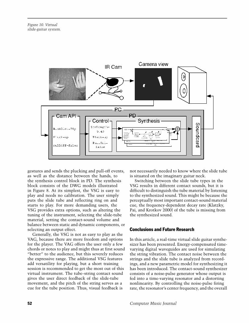
Figure 10. Virtualslide-guitar system.
gestures and sends the plucking and pull-off events,as well as the distance between the hands, tothe synthesis control block in PD. The synthesisblock consists of the DWG models illustratedin Figure 8. At its simplest, the VSG is easy toplay and needs no calibration. The user simplyputs the slide tube and reflecting ring on andstarts to play. For more demanding users, theVSG provides extra options, such as altering thetuning of the instrument, selecting the slide-tubematerial, setting the contact-sound volume andbalance between static and dynamic components, orselecting an output effect.
Generally, the VSG is not as easy to play as theVAG, because there are more freedom and optionsfor the player. The VAG offers the user only a fewchords or notes to play and might thus at first sound“better” to the audience, but this severely reducesthe expressive range. The additional VSG featuresadd versatility for playing, but a short trainingsession is recommended to get the most out of thisvirtual instrument. The tube–string contact soundgives the user direct feedback of the slide-tubemovement, and the pitch of the string serves as acue for the tube position. Thus, visual feedback is
not necessarily needed to know where the slide tubeis situated on the imaginary guitar neck.
Switching between the slide tube types in theVSG results in different contact sounds, but it isdifficult to distinguish the tube material by listeningto the synthesized sound. This might be because theperceptually most important contact-sound materialcue, the frequency-dependent decay rate (Klatzky,Pai, and Krotkov 2000) of the tube is missing fromthe synthesized sound.
Conclusions and Future Research
In this article, a real-time virtual slide guitar synthe-sizer has been presented. Energy-compensated time-varying digital waveguides are used for simulatingthe string vibration. The contact noise between thestrings and the slide tube is analyzed from record-ings, and a new parametric model for synthesizing ithas been introduced. The contact-sound synthesizerconsists of a noise-pulse generator whose output isfed into a time-varying resonator and a distortingnonlinearity. By controlling the noise-pulse firingrate, the resonator’s center frequency, and the overall
52 Computer Music Journal
dynamics with the sliding velocity, a realistic time-varying harmonic structure is obtained in the result-ing synthetic noise. The overall spectral shape of thecontact noise is set with a fourth-order IIR filter.
The slide-guitar synthesizer is operated using anoptical gesture-recognition user interface, similar tothe suggestion by Karjalainen et al. (2006). However,instead of a Web-camera, a high-speed infraredvideo camera is used for attaining a lower latencybetween the user’s gesture and the resulting sound.This IR-based camera system could also be usedfor gestural control of other latency-critical real-time applications. The real-time virtual slide guitarmodel has been realized in PD.
In the current implementation, the longitudinalstring vibrations are simulated with fixed filtersfor computational simplicity. This prevents themodeling of the longitudinal mode spectrum’sdependency on the sliding location (Pakarinen,Penttinen, and Bank 2007). The result of thisshortcoming is that the spectrum of the contactnoise is less dynamic than in reality. In a moresophisticated implementation, this effect could besimulated either by varying the contact-sound filterin time or adding a separate time-varying digitalwaveguide for modeling the longitudinal modes.Furthermore, the gesture-based user interface couldbe extended so that the user could, for example,play arpeggios by plucking individual strings. Also,the computational load of the control part could berelieved by operating the camera software on anothercomputer and transmitting the control data over thenetwork. These upgrades are left for future work.
Acknowledgments
The work of J. Pakarinen has been supported by theGETA graduate school, the Cost287-ConGAS action,and the Emil Aaltonen Foundation. The authors aregrateful to Professors Marcelo Wanderley and GaryScavone for helpful discussions.
References
Aramaki, M., and R. Kronland-Martinet. 2006. “Analysis-Synthesis of Impact Sounds by Real-Time Dynamic
Filtering.” IEEE Transactions on Audio, Speech andLanguage Processing 14(2):695–705.
Aramaki, M., et al. 2006. “A Percussive Sound Synthe-sizer Based on Physical and Perceptual Attributes.”Computer Music Journal 30(2):32–41.
Arfib, D. 1979. “Digital Synthesis of Complex Spectraby Means of Multiplication of Nonlinear DistortedSine Waves.” Journal of the Audio Engineering Society27(10):757–768.
Avanzini, F., S. Serafin, and D. Rocchesso. 2005. “In-teractive Simulation of Rigid Body Interaction withFriction-induced Sound Generation.” IEEE Transac-tions on Speech and Audio Processing 13(5):1073–1081.
Camurri, A., et al. 2000. “EyesWeb—Toward Gesture andAffect Recognition in Interactive Dance and MusicSystems.” Computer Music Journal 24(1):57–69.
Camurri, A., et al. 2005. “Communicating Expressivenessand Affect in Multimodal Interactive Systems.” IEEEMultimedia 12(1):43–53.
Cook, P. R. 1997. “Physically Informed Sonic Modeling(PhISM): Synthesis of Percussive Sounds.” ComputerMusic Journal 21(3):38–49.
Fontana, F. 2003. “Physics-Based Models for the AcousticRepresentation of Space in Virtual Environments.”Ph.D. dissertation, University of Verona, Italy. Availableonline at http://profs.sci.univr.it/∼fontana/paper/20.pdf.
Gorman, M., et al. 2007. “A Camera-Based Music-MakingTool for Physical Rehabilitation.” Computer MusicJournal 31(2):39–53.
Johnson, R. 1990. “The Complete Recordings.” Audiocompact disc. New York: Legacy Recordings C2K46222.
Karjalainen, M., et al. 2006. “Virtual Air Guitar.” Journalof the Audio Engineering Society 54(10):964–980.
Karjalainen, M., V. Valimaki, and T. Tolonen. 1998.“Plucked-String Models: From the Karplus-StrongAlgorithm to Digital Waveguides and Beyond.” Com-puter Music Journal 22(3):17–32.
Klatzky, R. L., D. K. Pai, and E. P. Krotkov. 2000. “Per-ception of Material from Contact Sounds.” Presence:Teleoperators and Virtual Environment 9(4):399–410.
Laakso, T. I., et al. 1996. “Splitting the Unit Delay—Tools for Fractional Delay Filter Design.” IEEE SignalProcessing Magazine 13(1):30–60.
Le Brun, M. 1979. “Digital Waveshaping Synthesis.”Journal of the Audio Engineering Society 27(4):250–266.
Pakarinen, J., H. Penttinen, and B. Bank. 2007. “Analysisof the Handling Noises on Wound Strings.” Journalof the Acoustical Society of America 122(6):EL197–EL202.
Pakarinen, Puputti, and Valimaki 53
Pakarinen, J., et al. 2005. “Energy Behavior in Time-Varying Fractional Delay Filters for Physical Modelingof Musical Instruments.” Proceedings of the IEEEInternational Conference on Acoustics, Speech andSignal Processing, Vol. 2. Piscataway, New Jersey:Institute of Electrical and Electronics Engineers,pp. 1–4.
Paradiso, J. A. 1997. “Electronic Music: New Ways toPlay.” IEEE Spectrum 34(12):18–30.
Peltola, L., et al. 2007. “Synthesis of Hand ClappingSounds.” IEEE Transactions on Audio, Speech, andLanguage Processing 15(3):1021–1029.
Penttinen, H., et al. 2006. “Model-Based Sound Synthesisof the Guqin.” Journal of the Acoustical Society ofAmerica 120(6):4052–4063.
Puckette, M. 1996. “Pure Data.” Proceedings of the1996 International Computer Music Conference. SanFrancisco, California: International Computer MusicAssociation, pp. 269–272.
Rath, M., and D. Rocchesso. 2005. “Continuous SonicFeedback from a Rolling Ball.” IEEE Multimedia12(2):60–69.
Rocchesso, D., R. Bresin, and M. Fernstrom. 2003.“Sounding Objects.” IEEE Multimedia 10(2):42–52.
Rocchesso, D., and F. Fontana, eds. 2003. The SoundingObject. Florence, Italy: Edizioni di Mondo Estremo.Available online at www.soundobject.org.
Smith, J. O. 1992. “Physical Modeling using DigitalWaveguides.” Computer Music Journal 16(4):74–91.
Valimaki, V., et al. 1996. “Physical Modeling of PluckedString Instruments with Application to Real-TimeSound Synthesis.” Journal of the Audio EngineeringSociety 44(5):331–353.
Valimaki, V., and T. Tolonen. 1998. “Development andCalibration of a Guitar Synthesizer.” Journal of theAudio Engineering Society 46(9):766–778.
Valimaki, V., et al. 2006. “Discrete-Time Modelling ofMusical Instruments.” Reports on Progress in Physics69(1):1–78.
Wanderley, M., and P. Depalle. 2004. “Gestural Control ofSound Synthesis.” Proceedings of the IEEE 92(4):632–644.
54 Computer Music Journal