kds3 manual final lr1
DESCRIPTION
Kds3 Manual Final Lr1TRANSCRIPT

Kawasaki Diagnostic Software Version 3KDS v.3
Instruction Manual

ForewordThis Instruction Manual explains the operating principles of KDS to diagnose Kawasaki’s Smart(KI-PASS), Digital Fuel Injection (DFI) and ABS systems. This manual is a brief introduction toKDS 3 and assumes that the technician is familiar with PC usage.
User License AgreementKawasaki Diagnostic System Software
This User License Agreement ("AGREEMENT") is a legal agreement between you (either anindividual or a single entity) and Kawasaki Heavy Industries, Ltd., a Japanese company,("Kawasaki") for the Kawasaki Diagnostic System software ("SOFTWARE"). By installing, copying,or otherwise using the SOFTWARE, you shall agree to be bound by the terms of thisAGREEMENT. If you do not agree to the terms of this AGREEMENT, promptly return the unusedSOFTWARE to the supplier from which you obtained it for a full refund.
1. COPYRIGHTAll title and copyrights in and to the SOFTWARE (including but not limited to any images,photographs, and text incorporated into the SOFTWARE) and the accompanying printed materialsare owned by Kawasaki. The SOFTWARE is protected with copyright laws and international treatyprovisions.
2. GRANT OF LICENSE1. By purchasing the CD-ROM which has the SOFTWARE in it, you are granted license of
Kawasaki's rights and you may use the SOFTWARE under following conditions (2) and (3).2. USE: The SOFTWARE is licensed, not sold. You may install and use one copy of the
SOFTWARE on your computer.3. COPY: You may either (a) make one copy of the SOFTWARE solely for backup or archival
purposes or (b) install the SOFTWARE on a single computer provided you keep the original solely for backup or archival purposes. All title and copyrights in and to the COPY are also owned by Kawasaki, and you may not use the COPY for any other purpose than to recover the SOFTWARE on your computer.
3. LIMITATIONSYou may not modify, reverse engineer, de-compile, or disassemble the SOFTWARE.
4. SOFTWARE TRANSFERYou may permanently transfer all of your rights under this AGREEMENT when the recipientagrees to the terms of this AGREEMENT, provided you retain no copies, you transfer all of the CD-ROM and printed materials accompanied with it.
5. TERMINATIONWithout prejudice to any other rights, Kawasaki may terminate this AGREEMENT if you fail tocomply with the terms and conditions of this AGREEMENT. In such event, you must uninstall theSOFTWARE and destroy all of the SOFTWARE, including its COPY if you have made one.

6. LIMITED WARRANTYKawasaki warrants that the CD-ROM with the SOFTWARE be free from defects in materials andworkmanship under normal use and service for a period of ninety (90) days from the date ofpurchase. Some countries, states or territories and jurisdictions do not allow limitations on durationof an implied warranty, so the above limitation may not apply to you. To the extent allowed byapplicable law, implied warranties on the SOFTWARE are limited to ninety (90) days.
1. CUSTOMER REMEDIES: Kawasaki's and its suppliers’ entire liability and your exclusive remedy shall be, at Kawasaki’ s option, either (a) return of the price paid, or (b) replacement of the SOFTWARE. This Limited Warranty is void if failure of the SOFTWARE has resulted from accident, abuse or misapplication
2. NO OTHER WARRANTIES: To the maximum extent permitted by applicable law, Kawasaki and its suppliers disclaim all other merchantability and fitness for a particular purpose, with regard to the SOFTWARE. This limited warranty gives you specific legal rights. You may have others, which vary from country, state or territory and jurisdiction to country, state or territory and jurisdiction.
3. NO LIABILITY FOR CONSEQUENTIAL DAMAGES: To the maximum extent permitted by applicable law, in no event shall Kawasaki or its suppliers be liable for any special, incidental, indirect, or consequential damages whatsoever (including, without limitation, damages for loss of business profits, business interruption, loss of business information, or any other pecuniary loss) arising out of the use of or inability to use the SOFTWARE, even if Kawasaki has been advised of the possibility of such damages. Because some countries, states or territories and jurisdictions do not allow the exclusion or limitation of liability for consequential or incidental damages, the above limitation may not apply to you.
7. EXPORT LIMITATIONYou shall agree not to export the CD-ROM with the SOFTWARE to foreign countries except forcomplying with local laws and rules.
8. COMMERCIAL ARBITRATIONIn case of trouble with the AGREEMENT, both parties assign Japan Commercial ArbitrationAssociation and under the rule thereof to settle a dispute and the award thereof shall be final andbinding upon both parties.
This KDS Version 3 uses encryption algorithm "MISTY" developed by MITSUBISHI ELECTRICCORPORATION".
Windows is the registered trade mark of Microsoft Corporation. And all the other brand names orproduct names are the company.
©2007 Kawasaki Heavy Industries, Ltd. Third Edition (3) 24 August, 2007

Contents
Section 1: Kawasaki Diagnostic System Version 3 Outline . . . . . . . . . . . . 11.1 System Function . . . . . . . . . . . . . . . . . . . . . . . . . . . . . . . . . . . . . . . . . . . . . . . . . . . . . . . 1
Smart System equipped Models . . . . . . . . . . . . . . . . . . . . . . . . . . . . . . . . . . . . . . . . . . . . . . . . . 1DFI equipped Vehicles . . . . . . . . . . . . . . . . . . . . . . . . . . . . . . . . . . . . . . . . . . . . . . . . . . . . . . . . 1ABS equipped Vehicles . . . . . . . . . . . . . . . . . . . . . . . . . . . . . . . . . . . . . . . . . . . . . . . . . . . . . . . . 1Other Features . . . . . . . . . . . . . . . . . . . . . . . . . . . . . . . . . . . . . . . . . . . . . . . . . . . . . . . . . . . . . . 1
1.2 KDS Version 3 System Configuration . . . . . . . . . . . . . . . . . . . . . . . . . . . . . . . . . . . . . . . 21.3 ZG1400A/B System Configuration . . . . . . . . . . . . . . . . . . . . . . . . . . . . . . . . . . . . . . . . . . 31.4 Personal Computer (PC) Minimum System Requirements for KDS 3 . . . . . . . . . . . . . . . 3
Section 2: Installation Procedures . . . . . . . . . . . . . . . . . . . . . . . . . . . . . . . . 42.1 Installation of KDS 3 Adapter . . . . . . . . . . . . . . . . . . . . . . . . . . . . . . . . . . . . . . . . . . . . . . 42.2 Initial Installation of KDS 3 Software . . . . . . . . . . . . . . . . . . . . . . . . . . . . . . . . . . . . . . . . 6
Section 3: Cable Connection . . . . . . . . . . . . . . . . . . . . . . . . . . . . . . . . . . . . . 93.1 Required Tools . . . . . . . . . . . . . . . . . . . . . . . . . . . . . . . . . . . . . . . . . . . . . . . . . . . . . . . . . 93.2 Connecting PC to ECU . . . . . . . . . . . . . . . . . . . . . . . . . . . . . . . . . . . . . . . . . . . . . . . . . . 9
3.2.1 ZG1400A/B . . . . . . . . . . . . . . . . . . . . . . . . . . . . . . . . . . . . . . . . . . . . . . . . . . . . . . . . . . . . . 93.2.2 ZX1200-A/B . . . . . . . . . . . . . . . . . . . . . . . . . . . . . . . . . . . . . . . . . . . . . . . . . . . . . . . . . . . 103.2.3 VN1500-P . . . . . . . . . . . . . . . . . . . . . . . . . . . . . . . . . . . . . . . . . . . . . . . . . . . . . . . . . . . . . 103.2.4 VN1600, VN2000 . . . . . . . . . . . . . . . . . . . . . . . . . . . . . . . . . . . . . . . . . . . . . . . . . . . . . . . 103.2.5 ZX636, ZX600, ZR1000, ZR750, ZX1000-C . . . . . . . . . . . . . . . . . . . . . . . . . . . . . . . . . . 113.2.6 JT1200B/D, JT1500A . . . . . . . . . . . . . . . . . . . . . . . . . . . . . . . . . . . . . . . . . . . . . . . . . . . . 113.2.7 VN900B/D . . . . . . . . . . . . . . . . . . . . . . . . . . . . . . . . . . . . . . . . . . . . . . . . . . . . . . . . . . . . . 113.2.8 ER650, EX650 . . . . . . . . . . . . . . . . . . . . . . . . . . . . . . . . . . . . . . . . . . . . . . . . . . . . . . . . . 123.2.9 ZX1400 . . . . . . . . . . . . . . . . . . . . . . . . . . . . . . . . . . . . . . . . . . . . . . . . . . . . . . . . . . . . . . . 123.2.10 KLE650 . . . . . . . . . . . . . . . . . . . . . . . . . . . . . . . . . . . . . . . . . . . . . . . . . . . . . . . . . . . . . . 123.2.11 ’07 ZR750/ZR1000 . . . . . . . . . . . . . . . . . . . . . . . . . . . . . . . . . . . . . . . . . . . . . . . . . . . . . 123.2.12 JT1500B/JT1500C . . . . . . . . . . . . . . . . . . . . . . . . . . . . . . . . . . . . . . . . . . . . . . . . . . . . . 133.2.13 KSF450B . . . . . . . . . . . . . . . . . . . . . . . . . . . . . . . . . . . . . . . . . . . . . . . . . . . . . . . . . . . . 133.2.14 VN1500-J/LIN/R . . . . . . . . . . . . . . . . . . . . . . . . . . . . . . . . . . . . . . . . . . . . . . . . . . . . . . . 13
Section 4: Menu Items . . . . . . . . . . . . . . . . . . . . . . . . . . . . . . . . . . . . . . . . . 144.1 Menu Structure . . . . . . . . . . . . . . . . . . . . . . . . . . . . . . . . . . . . . . . . . . . . . . . . . . . . . . . 144.2 Function of Menu Items . . . . . . . . . . . . . . . . . . . . . . . . . . . . . . . . . . . . . . . . . . . . . . . . . 15
Section 5: KDS 3 Operation for KI-PASS System . . . . . . . . . . . . . . . . . . . 165.1 Starting KDS 3 . . . . . . . . . . . . . . . . . . . . . . . . . . . . . . . . . . . . . . . . . . . . . . . . . . . . . . . . 165.2 Diagnosis. . . . . . . . . . . . . . . . . . . . . . . . . . . . . . . . . . . . . . . . . . . . . . . . . . . . . . . . . . . . 175.3 Real Time Monitor . . . . . . . . . . . . . . . . . . . . . . . . . . . . . . . . . . . . . . . . . . . . . . . . . . . . . 18
5.3.1 Selecting Display Items . . . . . . . . . . . . . . . . . . . . . . . . . . . . . . . . . . . . . . . . . . . . . . . . . . 185.3.2 Saving Service Data . . . . . . . . . . . . . . . . . . . . . . . . . . . . . . . . . . . . . . . . . . . . . . . . . . . . . 195.3.3 Printing . . . . . . . . . . . . . . . . . . . . . . . . . . . . . . . . . . . . . . . . . . . . . . . . . . . . . . . . . . . . . . . 20
5.4 Tire Air Pressure Measuring System(TPMS) Sensor Replacement . . . . . . . . . . . . . . . . . . . . . . . . . . . . . . . . . . . . . . . . . . . . 21
5.4.1 Deleting TPMS ID. . . . . . . . . . . . . . . . . . . . . . . . . . . . . . . . . . . . . . . . . . . . . . . . . . . . . . . 21
5.5 Fob Registration . . . . . . . . . . . . . . . . . . . . . . . . . . . . . . . . . . . . . . . . . . . . . . . . . . . . . . . 235.5.1 Additional Fob Registration . . . . . . . . . . . . . . . . . . . . . . . . . . . . . . . . . . . . . . . . . . . . . . . 235.5.2 Fob Re-registration . . . . . . . . . . . . . . . . . . . . . . . . . . . . . . . . . . . . . . . . . . . . . . . . . . . . . . 25
5.6 Immobilizer Key Registration (Smart ECU Replacement) . . . . . . . . . . . . . . . . . . . . . . . 265.7 FI ECU Replacement . . . . . . . . . . . . . . . . . . . . . . . . . . . . . . . . . . . . . . . . . . . . . . . . . . . 285.8 Steering Lock Unit (ECU) Replacement . . . . . . . . . . . . . . . . . . . . . . . . . . . . . . . . . . . . 295.9 Smart ECU Replacement . . . . . . . . . . . . . . . . . . . . . . . . . . . . . . . . . . . . . . . . . . . . . . . . 305.10 Smart System Parts Replace and KDS 3 Operation . . . . . . . . . . . . . . . . . . . . . . . . . . 31
Section 6: KDS 3 Operations for FI System . . . . . . . . . . . . . . . . . . . . . . . . 326.1 Starting KDS 3 . . . . . . . . . . . . . . . . . . . . . . . . . . . . . . . . . . . . . . . . . . . . . . . . . . . . . . . . 326.2 Real Time Monitor . . . . . . . . . . . . . . . . . . . . . . . . . . . . . . . . . . . . . . . . . . . . . . . . . . . . . 33
6.2.1 Selecting Display Items . . . . . . . . . . . . . . . . . . . . . . . . . . . . . . . . . . . . . . . . . . . . . . . . . . 336.2.2 Saving Service Data . . . . . . . . . . . . . . . . . . . . . . . . . . . . . . . . . . . . . . . . . . . . . . . . . . . . 356.2.3 Printing . . . . . . . . . . . . . . . . . . . . . . . . . . . . . . . . . . . . . . . . . . . . . . . . . . . . . . . . . . . . . . . 36
6.3 Diagnosis . . . . . . . . . . . . . . . . . . . . . . . . . . . . . . . . . . . . . . . . . . . . . . . . . . . . . . . . . . . . 366.4 Actuator Test . . . . . . . . . . . . . . . . . . . . . . . . . . . . . . . . . . . . . . . . . . . . . . . . . . . . . . . . . 37
6.4.1 Selecting Test Item . . . . . . . . . . . . . . . . . . . . . . . . . . . . . . . . . . . . . . . . . . . . . . . . . . . . . . 376.4.2 Selecting Display Items . . . . . . . . . . . . . . . . . . . . . . . . . . . . . . . . . . . . . . . . . . . . . . . . . . 376.4.3 Injector Operation Test . . . . . . . . . . . . . . . . . . . . . . . . . . . . . . . . . . . . . . . . . . . . . . . . . . . 376.4.4 Fuel Pump Test . . . . . . . . . . . . . . . . . . . . . . . . . . . . . . . . . . . . . . . . . . . . . . . . . . . . . . . . 386.4.5 Ignition Coil #No Test . . . . . . . . . . . . . . . . . . . . . . . . . . . . . . . . . . . . . . . . . . . . . . . . . . . . 396.4.6 Sub Throttle Valve Actuator Test . . . . . . . . . . . . . . . . . . . . . . . . . . . . . . . . . . . . . . . . . . . 396.4.7 Second Air Solenoid Test . . . . . . . . . . . . . . . . . . . . . . . . . . . . . . . . . . . . . . . . . . . . . . . . . 396.4.8 OCV Solenoid Test . . . . . . . . . . . . . . . . . . . . . . . . . . . . . . . . . . . . . . . . . . . . . . . . . . . . . . 40
6.5 Real Time Monitor (Graph) . . . . . . . . . . . . . . . . . . . . . . . . . . . . . . . . . . . . . . . . . . . . . . 406.5.1 Graph Display Items Selection . . . . . . . . . . . . . . . . . . . . . . . . . . . . . . . . . . . . . . . . . . . . . 416.5.2 Displaying Graphs . . . . . . . . . . . . . . . . . . . . . . . . . . . . . . . . . . . . . . . . . . . . . . . . . . . . . . 416.5.3 Printing . . . . . . . . . . . . . . . . . . . . . . . . . . . . . . . . . . . . . . . . . . . . . . . . . . . . . . . . . . . . . . . 41
Section 7: KDS for ABS System . . . . . . . . . . . . . . . . . . . . . . . . . . . . . . . . . 427.1 Outline . . . . . . . . . . . . . . . . . . . . . . . . . . . . . . . . . . . . . . . . . . . . . . . . . . . . . . . . . . . . . . 427.2 Installing the Software . . . . . . . . . . . . . . . . . . . . . . . . . . . . . . . . . . . . . . . . . . . . . . . . . . 427.3 Connection of the Cable . . . . . . . . . . . . . . . . . . . . . . . . . . . . . . . . . . . . . . . . . . . . . . . . 42
7.3.1 ZG1400A . . . . . . . . . . . . . . . . . . . . . . . . . . . . . . . . . . . . . . . . . . . . . . . . . . . . . . . . . . . . . 427.3.2 ER650B/EX650B . . . . . . . . . . . . . . . . . . . . . . . . . . . . . . . . . . . . . . . . . . . . . . . . . . . . . . . 437.3.3 ZX1400B . . . . . . . . . . . . . . . . . . . . . . . . . . . . . . . . . . . . . . . . . . . . . . . . . . . . . . . . . . . . . . 43
7.4 Menu Structure . . . . . . . . . . . . . . . . . . . . . . . . . . . . . . . . . . . . . . . . . . . . . . . . . . . . . . . 437.5 Operation . . . . . . . . . . . . . . . . . . . . . . . . . . . . . . . . . . . . . . . . . . . . . . . . . . . . . . . . . . . . 44
7.5.1 Starting KDS for ABS . . . . . . . . . . . . . . . . . . . . . . . . . . . . . . . . . . . . . . . . . . . . . . . . . . . . 44

KDS Version 3 Instruction Manual
Section 1: Kawasaki Diagnostic System Version 3 Outline
1.1 System FunctionKDS Version 3 was developed for Smart equipped Motorcycles with DFI, non-Smart equipped motorcycles with DFI, and DFI equipped PWC and ATV. The following functions are available.
Smart System equipped Models1. Register the Steering Lock unit, FI ECU2. Register the Fobs, Immobilizer key3. Register or delete the TPMS sensor ID4. Diagnose the Smart System5. Monitor the Smart System
NOTE~ Smart System components must be registered to the Smart ECU in order to function
correctly.
DFI equipped Vehicles1. Display ECU and model information 2. Perform diagnostics3. Display, save, and print service data4. Actuate individual injectors and other actuators5. Display, save, and print real-time sensor values6. Display and print graphs of real-time sensor values7. Erase stored service data
ABS equipped Vehicles1. Diagnose the ABS system2. Erase stored service data
Other Features1. Software can be used in ten languages.2. Software operates on Windows 2000/XP/Vista.3. Three units (SI, Metric, English) can be selected to display sensor values.
NOTE~ Some functions are not available on all models.
1

KDS Version 3 Instruction Manual
1.2 KDS Version 3 System ConfigurationKDS Version 3 operates on a PC and communicates with the unit via a USB communications port, communication cable, and a signal converter.KDS consist of, (1) CD, (2) Signal Converter, (3) Communication Cables. (Fig.1 shows the KDS 3 Kit parts for ZG1400A/B)..
(1) CD(KDS 3 software)P/NO. 57001-1650
(2) Adapter(Signal converter)P/No. 57001-1648
(3) Communication cablesP/No. 57001-1649 (6-pin/8-pin)P/No. 57001-1688 (8-pin/4-pin)
Fig. 1-1 KDS 3 Tools
A: Personal Computer (PC)C: Converter (57001-1648)E: Smart ECU
B: USB cableD: 6-pin connector of main harness
Fig. 1-2 Sample connection of ZG1400 system
A: Personal Computer (PC)C: Converter (57001-1648)E: 8-pin/4-pin cable (57001-1688)
B: USB cableD: 6-pin/8-pin cable (57001-1649)F: 4-pin connector of main harness
G: FI ECU
Fig. 1-3 Sample connection of other DFI vehicles
2

KDS Version 3 Instruction Manual
1.3 ZG1400A/B System Configuration
1.4 Personal Computer (PC) Minimum System Requirements for KDS 3Table 1-a PC Requirement
NOTE~ Do not use a screen saver.~ Do not use power management mode.~ When changing an ECU, exit KDS and then restart.~ You must use the PC as an administrator.~ USB cable should be purchased locally.
Hardware RequirementsCPU Pentium, 133 MHz or fasterOS (Operating System) Windows 2000/XP/VistaHard Disk 20 MB or more of free space (40 MB or more is recommended.)Display SVGADisk device CD-ROM or DVD drivePrinter Black and White or ColorInterface port USB portUSB Cable Should be used between PC and Converter.
BUFFALO, USBC2-SBK, (length: 2.0 m)If this cable is not available, use a similarly specified double shielded cable with a maximum length of 2 m.
3

KDS Version 3 Instruction Manual
Section 2: Installation ProceduresNOTE: All screenshots in this Manual are from a PC operating on Windows XP.You must install two software programs on your PC. One is for the KDS 3 Adapter (converter) and the other is for the KDS software.
2.1 Installation of KDS 3 Adapter
The PC detects the KDS Adapter and starts the Found New Hardware Wizard.o Select No, not this time; a new screen will appear.o Select Install from a specific location (Advanced) on the next screen.Then select Next>
o Start your PC, and then insert the CD (P/N 57001-1650).
o Open the CD, and save the KDSAdapter.inf and KDSAdapter.sys files to a location on your PC.
o Connect the KDS 3 Adapter (PN 57001-1648) to your PC with the USB cable.
NOTE~ Purchase a USB cable locally with a
maximum length no longer than 2m.
Fig. 2-1 Files in CD
o Connect the KDS Adapter to the connector (6-pin type) on the main harness.
o Turn ON the ignition.
KDS Adapter (Signal Converter)
Fig. 2-2 Starting the Wizard
4

KDS Version 3 Instruction Manual
Selection of Search Optiono Select Don’t search
Then select Next>
Fig. 2-3 Search Selection
Selection of Device Driver.o Select Show compatible hardwareo Select KDS Adaptero Then select Next>
Fig. 2-4 Selection of Device Driver
o Select the location of KDSAdapter.inf file.o Then select Open.
Fig. 2-5 Locate Driver Fig. 2-6 Selection of Driver
5

KDS Version 3 Instruction Manual
2.2 Initial Installation of KDS 3 Software
Installation in progress screen.
Fig. 2-7 Installation
o Finished: select Finish.
Fig. 2-8 Installation Complete
o Start Windows.o Insert the KDS CD into the CD drive.o CD autolaunches (or navigate to the drive
location then double click InstKDS.exe).
Fig. 2-9 KDS 3 File Folder
6

KDS Version 3 Instruction Manual
o Select the language.Then select OK.
Language abbreviation are as follows. DE: German, EL: Greek, EN: English,ES: Spanish, FR: French, IT: Italian,NL: Netherlands, PT: Portuguese,SV: Swedish
Fig. 2-10 Language Selection
Installation program starts automatically.o Select Next>
Fig. 2-11 Installation Wizard
o Select Installation Folder.The default folder is:C:\Program Files\Kawasaki Diagnostic System Ver.3
o Select Just meo Then select Next>
Fig. 2-12 Selection of Installation Folder
7

KDS Version 3 Instruction Manual
o Follow the on screen instructions.
Fig. 2-13 Install Shield Wizard
Installation in progress screen
Fig. 2-14 Beginning Installation
Installation completes.o Select Close
Fig. 2-15 Installation Complete
8

KDS Version 3 Instruction Manual
Section 3: Cable Connection
Detail of Connection1. Connect to main harness of vehicle2. USB port of KDS 3 Adapter3. Connect to KDS 3 Adapter4. Connect to PC5. 6-pin port, Connect to KDS 3 Adapter6. 8-pin port, Connect to ABS ECU port of main harness7. 8-pin port, Connect to No.6 port8. 4-pin port, Connect to KDS port of main harness
3.2 Connecting PC to ECURefer to the following diagrams or the Service Manual for the location of the diagnostic ports.
3.1 Required ToolsA. KDS 3 Adapter 57001-1648B. Com. Cable (6-pin/8-pin) 57001-1649C. KDS 3 Software 57001-1650D. Com. Cable (8-pin/4-pin) 57001-1688E. USB Cable
Fig. 3-1 Required Tools
3.2.1 ZG1400A/B(1) Smart and DFI systems
o Remove seat.o Locate the 6-pin connector [A] on the main
harness and remove the cover.o Connect the 6-pin connector to the Adapter
[B].o Connect the USB cable [C] to the Adapter.
Fig. 3-2.1 Tool Connection
9

KDS Version 3 Instruction Manual
(2) ABS systemo Remove seat.o Locate the 8-pin connector [A] on the main
harness and remove the cover (ABS port).o Connect cable 57001-1649 [B] to the 8-pin
ABS port.o Connect the 6-pin connector on 57001-
1649 to the Adapter [C].o Connect the computer’s USB cable [D] to
the Adapter.
Fig. 3-2.1.1 Tool Connection (ABS)
3.2.2 ZX1200-A/Bo Remove the (rear) compartment cover.o Remove the cover on the harness.o Connect the adapter cable to the diagnostic
port on harness
A. Diagnostic port (4-pin) on harnessB. Communication Cable
Fig. 3-2.2 Connection of ZX1200-A/B
3.2.3 VN1500-Po Remove the seat.o Remove the cover of Diagnostic Port [A].o Connect the adapter cable to the diagnostic
port on harness.
A. Diagnostic Port (4-pin)B. BatteryC. ECU
Fig. 3-2.3 Connection of VN1500-P
3.2.4 VN1600, VN2000o Remove the seat. --VN1600-A/Bo Remove the seat and battery cover –VN2000-Ao Remove the cover of Diagnostic Port [A].o Connect the adapter cable to the diagnostic port
on harness.
A. Diagnostic Port (4-pin)B. BatteryC. ECU
Fig. 3-2.4 Connection of VN1600-A
10

KDS Version 3 Instruction Manual
3.2.5 ZX636, ZX600, ZR1000, ZR750,ZX1000-Co Remove the seat.o Remove the cover of Diagnostic Port [A].o Connect the adapter cable to the diagnostic
port on harness.
A. Diagnostic Port (4-pin)B. BatteryC. ECU
Fig. 3-2.5 Connection of ZX636-B
3.2.6 JT1200B/D, JT1500Ao Remove the seat and rear storage pocket.o Disconnect the 8-pin connector [C] and
insert the relay cable (57001-1535) between the connector.
o Connect the lead of relay cable to the (-) terminal of battery.
o Remove the cover of diagnostic port [A].o Connect the adapter cable to the diagnostic
port on harness.
A. Diagnostic Port (4-pin)B. Relay AssemblyC. 8-pin ConnectorD. Battery
~ The relay cable must be connected to prevent loss of communication due to the ECU timing out if the engine is not started.
Fig. 3-2.6 Connection of JT1200-B
3.2.7 VN900B/Do Remove the seat.o Remove the right side cover [A].o Access to the Diagnostic Port [B] from right
side.o Remove the cover and connect the adapter
cable to the diagnostic port on harness.
A. Right Side CoverB. Diagnostic Port (4-pin)
Fig. 3-2.7 Connection of VN900-B/D
11
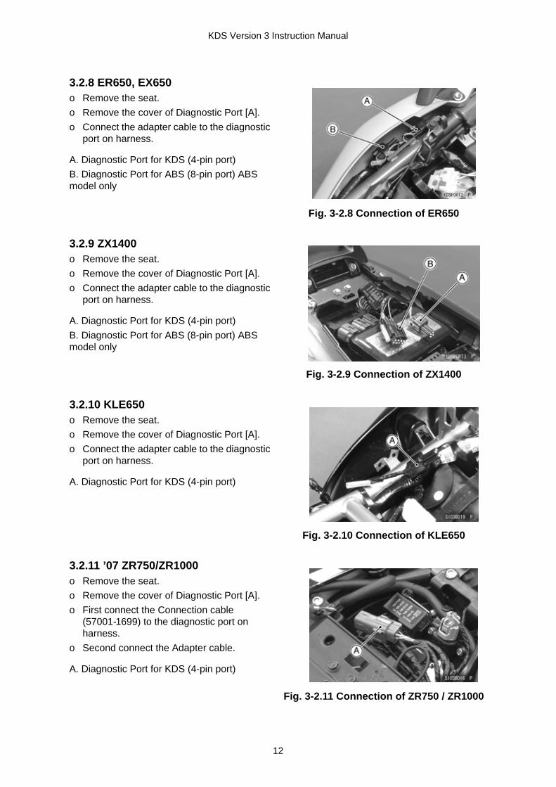
KDS Version 3 Instruction Manual
3.2.8 ER650, EX650o Remove the seat.o Remove the cover of Diagnostic Port [A].o Connect the adapter cable to the diagnostic
port on harness.
A. Diagnostic Port for KDS (4-pin port)B. Diagnostic Port for ABS (8-pin port) ABS model only
Fig. 3-2.8 Connection of ER650
3.2.9 ZX1400o Remove the seat.o Remove the cover of Diagnostic Port [A].o Connect the adapter cable to the diagnostic
port on harness.
A. Diagnostic Port for KDS (4-pin port)B. Diagnostic Port for ABS (8-pin port) ABS model only
Fig. 3-2.9 Connection of ZX1400
3.2.10 KLE650o Remove the seat.o Remove the cover of Diagnostic Port [A].o Connect the adapter cable to the diagnostic
port on harness.
A. Diagnostic Port for KDS (4-pin port)
Fig. 3-2.10 Connection of KLE650
3.2.11 ’07 ZR750/ZR1000o Remove the seat.o Remove the cover of Diagnostic Port [A].o First connect the Connection cable
(57001-1699) to the diagnostic port on harness.
o Second connect the Adapter cable.
A. Diagnostic Port for KDS (4-pin port)
Fig. 3-2.11 Connection of ZR750 / ZR1000
12

KDS Version 3 Instruction Manual
3.2.12 JT1500B/JT1500Co Open the front storage compartment cover.o Remove the front storage case.o Push in the pins and remove the battery
cover.o Connect the communication cable to the
Diagnostic Port [A] near the battery.
A. Diagnostic Port for KDS (4-pin port)
Fig. 3-2.12 Connection of JT1500B / JT1500C
o Insert the Adapter cable (57001-1696) between the 6-pin connector [B] on harness.
o Then connect the leads of the Adapter cable.
Fig. 3-2.12.1 Connection of JT1500B / JT1500C
3.2.13 KSF450Bo Remove the cover of Diagnostic Port [A].o Connect the adapter cable to the diagnostic
port on harness.The port is located under the front fender (left side).
A. Diagnostic Port for KDS (4-pin port)
Fig. 3-2.13 Connection of KSF450B
3.2.14 VN1500-J/L/N/Ro Remove the seat and battery holder.o Pull out the ECU from the case.o Remove the 8-Pin cover from ECU &
connect the cable to 8-pin port of ECU
A. ECU B. Communication Cable
Fig. 3-2.14 Connection of VN1500
13

KDS Version 3 Instruction Manual
Section 4: Menu Items
4.1 Menu StructureThe menu structure diagram and menu items outline are as shown in Fig. 4-1 and Table 4-a, followed by further explanation on each menu. Some functions are not available on all models.
Fig. 4-1 Menu Structure
14

KDS Version 3 Instruction Manual
4.2 Function of Menu Items
Table 4-a Menu Feature
Menu Item Description & Function
With Smart System Select for ZG1400A/B
Without Smart System Select for all non Smart equipped models
Model Information Displays model information
KI-PASS Select when diagnosing/servicing KI-PASS system and parts
KI-PASS Related Menu Select when diagnosing/servicing KI-PASS system and parts
Unit Registration Select when servicing Steering Lock Unit or FI ECU
FOB Registration Select when registering FOB
Diagnosis Select when diagnosing KI-PASS system
Immobilizer Key Registration Select when registering Immobilizer Key
Tire Air Pressure SensorID registration
Select when registering TPMS ID
Tire Air Pressure SensorID deletion
Select when deleting TPMS ID
Real Time Monitor Show current situation of KI-PASS system
Fuel Injection Select when diagnosing FI system and parts
FI ECU Related Menu Select when diagnosing/monitoring FI system and parts
Real Time Monitor Displays engine running conditions and previous codes
Actuator Test Run or stop the actuator
Graph Draw and display the graph.
Real Time Monitor Displays engine running conditions and previous codes.
Diagnosis Displays self-diagnosing codes stored on the ECU
ABS Select when diagnosing ABS system
ABS Current Failure Show current failure of ABS system
Intermittent Failure Show previous failure of ABS system
Erase Stored Service Codes Erase service codes
15

KDS Version 3 Instruction Manual
Section 5: KDS 3 Operation for KI-PASS SystemThe ZG1400A/B KI-PASS (Smart) system requires code verification for the ECU units to function correctly.
5.1 Starting KDS 3o Turn on the PCo Start KDS Version 3 from the start menu.
Or double-click the KDS 3 icon on the desktop screen.
Fig. 5-1 KDS 3 icon
Fig. 5-2 will appear.o Read the instructions and perform the
preliminary inspection.o Select OK after performing the preliminary
inspection.
Fig. 5-2 Important Screen
Fig. 5-3 will appear.o On Smart System equipped models, select
With Smart System.
Fig. 5-3 Main Menu
16

KDS Version 3 Instruction Manual
5.2 Diagnosis.
o The KDS Main Menu and Model Information screen will appear.
o Select KI-PASS.
Fig. 5-4 Main Menu & Model Information
o Select one of the options from the KI-PASS Related Menu
Fig. 5-5 KI-PASS Related Menu & ECU Part Number
o Select Diagnosis on the KI-PASS Related Menu to display current failure codes
Fig. 5-6 is a sample screen.
Fig. 5-6 Diagnosis
17

KDS Version 3 Instruction Manual
5.3 Real Time Monitor
5.3.1 Selecting Display Items
o To display current KI-PASS component condition, select Real Time Monitor in the KI-PASS Related Menu.
Fig. 5-7 is a sample screen.
Fig. 5-7 Real Time Monitor
o First select the group from the pull down menu.There are four groups:Engine Information, Warning Information, Monitoring Information, and All Information.
All Information includes Engine, Warning and Monitor Information.
o Choose Select.
Fig. 5-8 Real Time Monitor
Fig. 5-9 will appear.o Select items and then select OK
On this screen, items can be selected and displayed for service information.
NOTE~ Use the "space" key to check or uncheck
each item for display purpose.~ Press the "arrow" keys (upward or
downward) on the keyboard to move the items.
Fig. 5-9 Select Items
18

KDS Version 3 Instruction Manual
5.3.2 Saving Service Data
Fig. 5-10 is a sample screen
Fig. 5-10 Real Time Monitor
NOTE~ To see the screen more clearly, you can
maximize the screen and enlarge the column widths (Fig. 5-11).
Fig. 5-11 Real Time Monitor
Data obtained through communication with the ECU can be saved.o Select Save (Fig. 5-11).o Select one option and then select OK
(Fig. 5-12).
Fig. 5-12 Select Save Option
o Enter comment then select OK (Fig. 5-13).
Fig. 5-13 Comment (sample)
19

KDS Version 3 Instruction Manual
5.3.3 PrintingData obtained through communication with the ECU can be printed.
o Fig. 5-14 appears. Select a folder and select Enter or Save to save the data as a CSV file.By default, the file name will consist of YY(year)MM(month)DD(day) and two incremental numeric digits (00-99). ECU Parts No., Model Name, Model Year & Specification are saved automatically in the data.
NOTE:CSV: comma separated value
Fig. 5-14 Save Folder (sample)
o A message will appear after saving the file. Select OK (Fig. 5-15).
Fig. 5-15 Save Completed
o Select Print (Fig. 5-11). Fig. 5-16 will appear.o Select a print option and select OK to print.
~ If a printer is not connected to the PC, a screen print will be created.
o Select Cancel to return to the previous screen.
Fig. 5-16 Print Option
20
KDS Version 3 Instruction Manual
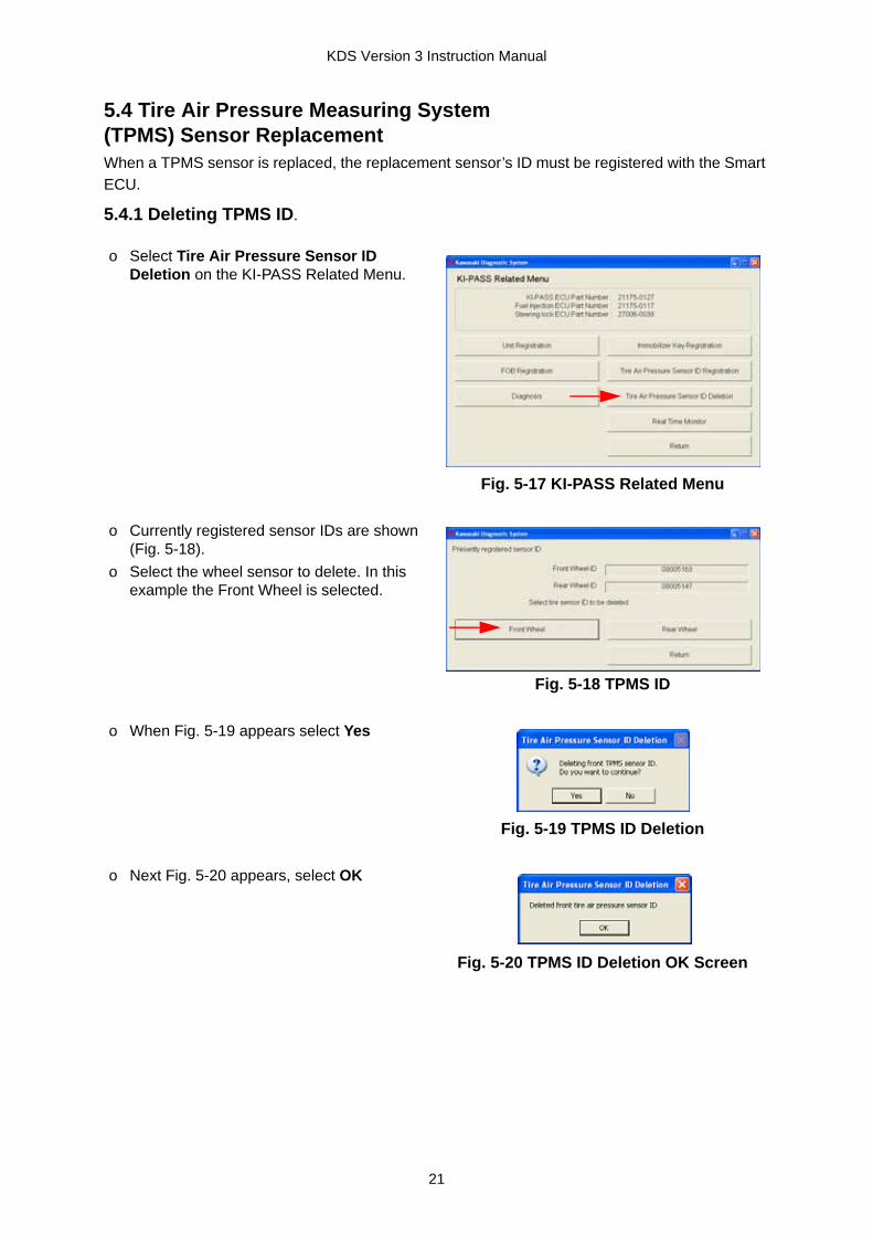
5.4 Tire Air Pressure Measuring System(TPMS) Sensor ReplacementWhen a TPMS sensor is replaced, the replacement sensor’s ID must be registered with the Smart ECU. 5.4.1 Deleting TPMS ID.
o Select Tire Air Pressure Sensor ID Deletion on the KI-PASS Related Menu.
Fig. 5-17 KI-PASS Related Menu
o Currently registered sensor IDs are shown (Fig. 5-18).
o Select the wheel sensor to delete. In this example the Front Wheel is selected.
Fig. 5-18 TPMS ID
o When Fig. 5-19 appears select Yes
Fig. 5-19 TPMS ID Deletion
o Next Fig. 5-20 appears, select OK
Fig. 5-20 TPMS ID Deletion OK Screen
21

KDS Version 3 Instruction Manual
o Prepare a new TPMS sensor and record the ID.~ TPMS sensors cannot be registered without ID registration.
o Replace the front TPMS sensor.o Select TPMS ID Registration on the KI-PASS Related Menu screen.
o On Fig. 5-21 the Front Wheel ID is changed to 00000000. Next select Return
Fig. 5-21 TPMD ID Deletion
o Fig. 5-22 appears, select Front Wheel.
Fig. 5-22 TPMD ID Registration
o When Fig. 5-23 appears, input the new TPMS ID and select Registration.
Fig. 5-23 TPMS ID Registration
o Fig. 5-24 appears, select Yes.
Fig. 5-24 TPMS ID Registration
o Fig. 5-25 appears, select OK.
Fig. 5-25 TPMS ID Registration
22

KDS Version 3 Instruction Manual
5.5 Fob RegistrationTo register an additional fob or to re-register an existing fob:
NOTE~ The maximum number of fobs that can be registered is 6. The motorcycle comes with 2, and
an additional 4 can be registered. A fob’s memory slot in the Smart ECU cannot be erased.
5.5.1 Additional Fob Registration
Fig. 5-26 appears.o Select Return.
Fig. 5-26 TPMS ID Registration
o To confirm the new TPMS ID is registered correctly, go to Real Time Monitor screen (Fig. 5-27)
Fig. 5-27 Registration Confirmation
o Select Fob Registration on the KI-PASS Related Menu (Fig. 5-28).
Fig. 5-28 KI-PASS Related Menu Screen
23

KDS Version 3 Instruction Manual
o Current information is displayed (Fig. 5-29).~ Two fobs are registered to the Smart
ECU during production. o Select Additional Registration if you want
to register additional fobs.
Fig. 5-29 Fob Registration Screen
Fig. 5-30 appears. o Input the new fob ID, then select Additional
Registration with the new fob placed close to the Smart ECU.
NOTE~ The new fob’s ID is located on the
shipping package.Fig. 5-30 Fob Registration
Fig. 5-31 appears.o Select OK.
Fig. 5-31 Fob Registration
Fig. 5-32 appears. o Select Return if you are finished, or
Additional Registration to register another fob.
Fig. 5-32 Fob Registration
Fig. 5-33 is a sample of an additional registration. o Enter the fob’s ID number and select
Additional Registration.
Fig. 5-33 Additional Registration
24

KDS Version 3 Instruction Manual
5.5.2 Fob Re-registration
Fig. 5-34 appears.o Select Return if completed.
Fig. 5-34 Additional Registration
o Select Re-registration (Fig. 5-34). Select OK (Fig. 5-35). In this example there are 3 fobs.
Fig. 5-35 Re-registration
o Fig. 5-36 appears confirming the number of fobs, select Yes.
Fig. 5-36 Re-registration
Fig. 5-37 appears.o Select Return if completed.
Fig. 5-37 Re-registration
25

KDS Version 3 Instruction Manual
5.6 Immobilizer Key Registration (Smart ECU Replacement)To register the Immobilizer keys supplied with a new Smart ECU:
o Select Immobilizer Key Registration on the KI-PASS Related Menu ( Fig. 5-38).
Fig. 5-38 KI-PASS Related Menu
Fig. 5-39 appears.o Select Immobilizer Key Registration.
Fig. 5-39 Immobilizer Key Registration
Fig. 5-40 appears.
Fig. 5-40 Immobilizer Key Registration
o Remove the key from the fob. Place the fob’s cutout (where the head of the key was located) over the projection in front of the ignition switch (See Fig. 5-41).
Fig. 5-41 Location of Key
26

KDS Version 3 Instruction Manual
Fig. 5-42 appears, select OK.
Fig. 5-42 Key Registration OK
A confirmation screen will appear. (Fig. 5-43).o To register more fobs, repeat the procedure.
When Fig. 5-41 appears, select OK.
Fig. 5-43 Updated Immobilizer Key Registration
Fig. 5-44 appears. o When all fobs have been registered, select
Confirm changed item.
Fig. 5-44 Confirmed Key Registration
Fig. 5-45 appearso Select Yes.
Fig. 5-45 Key Registration
Fig. 5-46 appears.o Select OK.
Fig. 5-46 Confirmation
27

KDS Version 3 Instruction Manual
5.7 FI ECU ReplacementTo replace the FI ECU:
Fig. 5-47 appears. o Select Return to complete the process.
Fig. 5-47 Confirmation
o Select Unit Registration on the KI-PASS Related Menu. (Fig. 5-48).
Fig. 5-48 KI-PASS Related Menu
o Select FI ECU, then select Registration (Fig. 5-49).
Fig. 5-49 FI ECU Selection
Fig. 5-50 appears.o Select Yes.
Fig. 5-50 FI ECU Selection
Fig. 5-51 appears.o Select OK.
Fig. 5-51 FI ECU Registration
28

KDS Version 3 Instruction Manual
5.8 Steering Lock Unit (ECU) ReplacementTo replace the Steering Lock ECU:
Fig. 5-52 appears.o Select Return.
Fig. 5-52 FI ECU Registration
Fig. 5-53 appears.o Select OK.This completes the registration process.
Fig. 5-53 ECU Registration
o Replace the Steering Lock Unit.o Start KDS 3 and go to the Main Menu, but
do not select any options yet.o Depress the steering lock switch (do not
turn switch). Select With Smart System within 10 seconds (Fig. 5-54).
Fig. 5-54 KDS Main Menu
Fig. 5-55 appears. o Select Steering Lock Unit Registration.
Fig. 5-55 Selection
Fig. 5-56 appears.o Select Yes.
Fig. 5-56 Starting Registration
29

KDS Version 3 Instruction Manual
5.9 Smart ECU ReplacementTo replace the Smart ECU:The Smart ECU is provided with two fob keys as a set.
o On completion of this procedure KDS 3 will close.o Confirm the release of the steering lock by pushing the switch ON.o Confirm meter operation by turning on the ignition switch.o After turning the ignition switch ON, reconnect KDS 3 and register the Immobilizer Keys and
TPMS sensors according to sections 5.6 and 5.4.
Fig. 5-57 appears. o Select OK.
Fig. 5-57 Registration
Fig. 5-58 appears.o Select OK.
Re-start KDS 3 and turn ON the vehicle.
Fig. 5-58 Registration Finished
o Replace the Smart ECU.o Start KDS 3 and go to the Main Menu (Fig.
5-59), but do not select any options yet.o After depressing the steering lock switch
(do not turn switch), select With Smart System.
o Register the steering lock unit as outlined in section 5.8.
Fig. 5-59 KDS Main Menu
30

5.10 Smart System Parts Replace and KDS 3 OperationNo Replacement Parts
KDS 3 OperationRemarks
Steering Lock ECU
Smart ECU
FI ECU
TPMS Fob Key
1 o - - - - 1Start KDS.2Steering lock push-switch ON, then start communication.3Register steering lock unit compulsory.4KDS closes. After steering lock switch ON, confirm the release of steering lock.
o Steering lock unit ID is necessary for Smart ECU registration.
2 - o - - o 1Start KDS.2Steering lock push-switch ON, then start communication. 3Register steering lock unit compulsory.4KDS closes. After steering lock switch ON, confirm the release of steering lock.5Confirm meter initialization.6Ignition switch ON, register immobilizer key and TPMS.
o Steering lock unit IDo FI-ECU IDo Immobilizer IDo TPMS ID
3 - - o - - 1 Ignition switch ON, Start KDS.2 Register FI-ECU compulsory.3After steering lock switch ON, confirm the release of steering lock. Confirm meter initialization.
o FI-ECU ID
4 - - - o - 1 Ignition switch ON, Start KDS.2 Register TPMS sensor ID.
o TPMS ID
5 o o - - o 1Start KDS.2Steering lock push-switch ON, then start communication. 3Register steering lock unit compulsory.4KDS closes. After steering lock switch ON, confirm the release of steering lock.5Confirm meter initialization.6Ignition switch ON, register immobilizer key and TPMS.
o Steering lock unit IDo FI-ECU IDo Immobilizer IDo TPMS ID
6 - o o - o 1Start KDS.2Steering lock push-switch ON, then start communication. 3Register steering lock unit compulsory.4KDS closes. After steering lock switch ON, confirm the release of steering lock.5Confirm meter initialization.6Ignition switch ON, register immobilizer key and TPMS.
o Steering lock unit IDo FI-ECU IDo Immobilizer IDo TPMS ID
7 o - o - - 1Start KDS.2Steering lock push-switch ON, then start communication. 3Register steering lock unit compulsory.4KDS closes. After steering lock switch ON, confirm the release of steering lock.5Confirm meter initialization.
o Steering lock unit IDo FI-ECU ID
8 o o o - o 1Put No.1 fob close to steering lock and push-switch ON.2Registering immobilizer key, show “Registration OK”, if not, show “Registration no good”.3 Put No.2 fob close to steering lock and push-switch ON.4If immobilizer key is registered successfully, automatically write the ID to steering lock ECU and display the mark which show ignition switch ON.5If ignition switch ON, write the ID to the FI-ECU, and initialize the Meter unit.
o Steering lock unit IDo FI-ECU IDo Immobilizer IDo TPMS ID
9 - - - - o When all fob keys are lost, Smart ECU must be replaced. The same operation with No. 2 is necessary.When registering additional fob, minimum one available fob is necessary.
o New fob ID
KDS Version 3 Instruction Manual
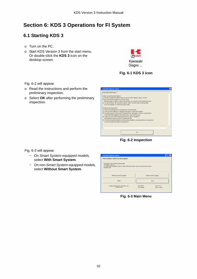
Section 6: KDS 3 Operations for FI System
6.1 Starting KDS 3
o Turn on the PC.o Start KDS Version 3 from the start menu.
Or double-click the KDS 3 icon on the desktop screen.
Fig. 6-1 KDS 3 icon
Fig. 6-2 will appear.o Read the instructions and perform the
preliminary inspection.o Select OK after performing the preliminary
inspection.
Fig. 6-2 Inspection
Fig. 6-3 will appear.~ On Smart System equipped models,
select With Smart System.~ On non-Smart System equipped models,
select Without Smart System.
Fig. 6-3 Main Menu
32
KDS Version 3 Instruction Manual
6.2 Real Time Monitor
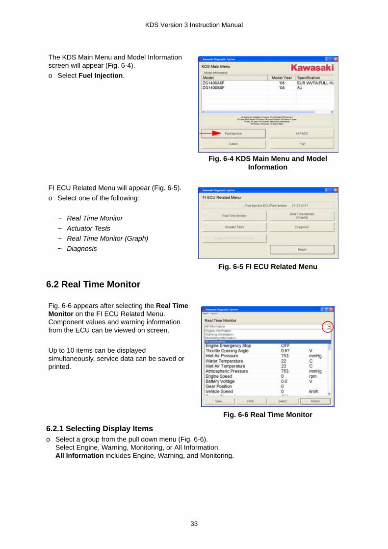
6.2.1 Selecting Display Itemso Select a group from the pull down menu (Fig. 6-6).
Select Engine, Warning, Monitoring, or All Information.All Information includes Engine, Warning, and Monitoring.
The KDS Main Menu and Model Information screen will appear (Fig. 6-4).o Select Fuel Injection.
Fig. 6-4 KDS Main Menu and Model Information
FI ECU Related Menu will appear (Fig. 6-5).o Select one of the following:
~ Real Time Monitor~ Actuator Tests~ Real Time Monitor (Graph)~ Diagnosis
Fig. 6-5 FI ECU Related Menu
Fig. 6-6 appears after selecting the Real Time Monitor on the FI ECU Related Menu. Component values and warning information from the ECU can be viewed on screen.
Up to 10 items can be displayed simultaneously, service data can be saved or printed.
Fig. 6-6 Real Time Monitor
33

KDS Version 3 Instruction Manual
o Click Select (Fig. 6-6).Fig. 6-7 will appear.On this screen, items can be selected and displayed for service information.
NOTE~ Use the space key to check or uncheck
each item for display purpose.~ Press the arrow keys (upward or
downward) on the keyboard to move the items.
o To confirm your selection, select OK or press the Enter key. To return to the previous selection, select Cancel.
Fig. 6-7 Select Items
Fig. 6-8 is a sample of All Information.~ Other items selected to be monitored
can be seen by selecting the scroll button or moving the scroll bar.
Fig. 6-8 Real Time monitor
Selection of unitso Select View(V) located on the upper Tool
Bar, then select Unit(U).
Fig. 6-9 appears.
o Select units from pull down menu.o After confirming the units, select OK.
Once units are selected they will be applied to all displays.
Fig. 6-9 Unit Selection
34

KDS Version 3 Instruction Manual
6.2.2 Saving Service Data
Data obtained through communication with the ECU can be saved.o Select Save (Fig. 6-8).
Fig. 6-10 will appear.
o Select an option and then select OK.
Fig. 6-10 Select Save Option
o Enter comment then select OK (Fig. 6-11).
Fig. 6-11 Comment (sample)
Fig. 6-12 appears.o Select a folder and press Enter or Save to
save the data under a CSV file.The file name by default will consist of YY(year)MM(month)DD(day) and two incremental numeric digits (00-99). ECU Parts No., Model Name, Model Year, and Specification are saved automatically in the data.
NOTE:CSV: comma separated value
Fig. 6-12 Save Folder (sample
o A message will appear after saving the file. Select OK.
Fig. 6-13 Saving Completed
35

KDS Version 3 Instruction Manual
6.2.3 PrintingAll or selected data from the ECU can be printed.
6.3 Diagnosiso Select Diagnosis on the FI ECU Related Menu. (Fig. 6.5).
By Clicking Print at Fig. 6-8, Fig. 6-14 appears.o Select a print option and select OK to print.
~ If a printer is not connected to the PC, a screen print will be created.
o Select Cancel to return to the previous screen.
Fig. 6-14 Print Option
o If there are no failures, the message No service codes exist appears.
o If a failure exists, it will be listed.Note
~ Five items or less can be displayed at a time.
~ Select the scroll button to see the messages
Fig. 6-15 FI ECU Diagnosis
o Select Failure history (Fig. 6-15) to see previous problems.~ Latest three records are shown.~ On some models latest two records are
shown.Note
~ From the pull down menu you can select Engine, Warning, Monitoring or All Information.
~ Failure history can be saved and printed in the same way as the Real Time Monitor.
Fig. 6-16 Failure history
36

KDS Version 3 Instruction Manual
6.4 Actuator Test
6.4.1 Selecting Test Item
6.4.2 Selecting Display ItemsAfter selecting the actuator test item, select Engine Information in the combo box.The procedure is the same as 6.2.1.
6.4.3 Injector Operation Test
To perform an Actuator Test select Actuator Tests on the FI ECU Related Menu.o First, select Actuator Test item.o Second, select display items.
~ While the test is running, the parameter values will be displayed.
~ Up to five parameters can be displayed at a time. Click the scroll buttons to scroll by line.
Fig. 6-17 FI ECU Related Menu
Fig. 6-18 appears after Actuator Tests is selected.o Select the test item from the pull down
menu list.
NOTE~ Available actuator test items for each
model are displayed on the screen.
Fig. 6-18 Actuator test selection
o Select Injector number to be testedo Select display items.o Run engine at idle speed.o Select Start to begin test (Fig. 6-19).
Fig. 6-19 Injector Test
37

KDS Version 3 Instruction Manual
Select Stop to finish testing. The test lasts for about 5 seconds and will stop automatically.
6.4.4 Fuel Pump Test
o While the engine is running, monitor the change in Engine Speed (and listen to the engine).
Fig. 6-20 is a sample of the injector operation test.
Fig. 6-20 Injector Test
Fig. 6-21 shows the injector test has been completed.
Fig. 6-21 Test Completed
o Select Fuel Pump Test from the pull down menu and select OK.
o Select display items.o Make sure the engine is not running and
select Start.Fig. 6-22 is displayed when performing the test.o Listen carefully for the sound of fuel pump
operation. If the operating sound is not heard, the fuel pump and/or its electrical circuit have failed.
o Select Stop to finish testing. The test lasts for about 5 seconds and will stop automatically.
Fig. 6-22 Fuel Pump Test
38
KDS Version 3 Instruction Manual
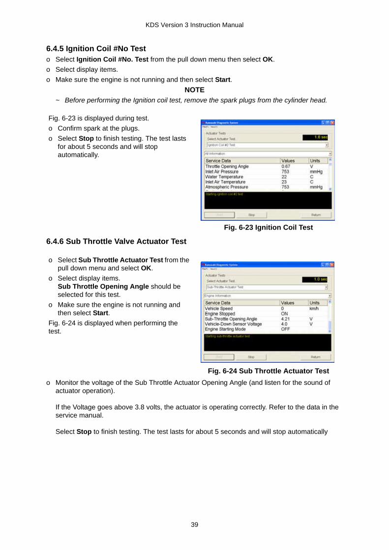
6.4.5 Ignition Coil #No Testo Select Ignition Coil #No. Test from the pull down menu then select OK.o Select display items.o Make sure the engine is not running and then select Start.
NOTE~ Before performing the Ignition coil test, remove the spark plugs from the cylinder head.
6.4.6 Sub Throttle Valve Actuator Test
o Monitor the voltage of the Sub Throttle Actuator Opening Angle (and listen for the sound of actuator operation).
If the Voltage goes above 3.8 volts, the actuator is operating correctly. Refer to the data in the service manual.
Select Stop to finish testing. The test lasts for about 5 seconds and will stop automatically
Fig. 6-23 is displayed during test.o Confirm spark at the plugs.o Select Stop to finish testing. The test lasts
for about 5 seconds and will stop automatically.
Fig. 6-23 Ignition Coil Test
o Select Sub Throttle Actuator Test from the pull down menu and select OK.
o Select display items.Sub Throttle Opening Angle should be selected for this test.
o Make sure the engine is not running and then select Start.
Fig. 6-24 is displayed when performing the test.
Fig. 6-24 Sub Throttle Actuator Test
39

KDS Version 3 Instruction Manual
6.4.7 Second Air Solenoid Testo Select Second Air Solenoid Test and select OK.o Select Display Items.o Make sure the engine is not running and then select Start.
6.4.8 OCV Solenoid Testo Select OCV Solenoid Test and then select OK.o Select display items.o Make sure the engine is not running and then select Start.
6.5 Real Time Monitor (Graph)The graph operates while the engine is running.Parameter values from the ECU will be shown on the graphs.Up to three graphs can be displayed and drawn for up to twenty seconds. They are drawn by scrolling point by point.Simultaneously, numerical values are displayed on screen.
Fig. 6-25 is displayed when performing the test.o Listen for the sound of solenoid operation.
If the operating sound is not heard, the solenoid or it’s circuit has failed.
o Select Stop to finish testing. The test lasts for about 5 seconds and will stop automatically.
Fig. 6-25 Second Air Solenoid Test
Fig. 6-26 is displayed when performing the test.o Listen for the sound of solenoid operation.
If the operating sound is not heard, the solenoid or it’s circuit has failed.
o Select Stop to finish testing. The test lasts for about 5 seconds and will stop automatically
Fig. 6-26 OCV Solenoid Test
40

KDS Version 3 Instruction Manual
6.5.1 Graph Display Items SelectionSelect Real Time Monitor (Graph) from the FI ECU Related Menu, then Select.
6.5.2 Displaying Graphs
6.5.3 Printing
Fig. 6-27 appears.o Select the item(s) on the pull down menu,
then OK or press the Enter key to confirm.o Select Cancel to stop.
Fig. 6-27 Selecting Items
o Select Start to display the graphs.o Select Stop to stop.
NOTE~ When displaying the graphs, the Start
button changes to a Stop button.
Fig. 6-28 Graph (sample)
o After selecting Print, Fig. 6-29 will appear.o Select the start time, and then select OK to
begin printing. (Print size: A4).Select Cancel to stop printing and return to the original screen.
Fig. 6-29 Printing Graph
o When printing has finished, the completion screen appears. Select OK.
Fig. 6-30 Printing Completed
41
KDS Version 3 Instruction Manual
Section 7: KDS for ABS System
7.1 OutlineKDS for ABS has been developed as an optional function of KDS 3. This software can be used on models equipped with ABS, such as the EX650B, ER650B, ZX1400B, and ZG1400A.
7.2 Installing the Software
7.3 Connection of the CableFig. 7-2 shows a sample connection of KDS for ABS.
Fig. 7-2 Sample connection of KDS-ABS systemA: Personal Computer (PC) B: USB cableC: Converter (57001-1648) D: Communication cable (6-pin/8-pin cable (57001-1649))E: 8-pin connector to main harness F: ABS ECU
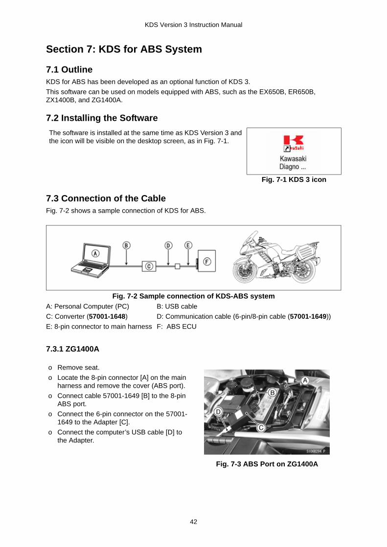
7.3.1 ZG1400A
The software is installed at the same time as KDS Version 3 and the icon will be visible on the desktop screen, as in Fig. 7-1.
Fig. 7-1 KDS 3 icon
o Remove seat.o Locate the 8-pin connector [A] on the main
harness and remove the cover (ABS port).o Connect cable 57001-1649 [B] to the 8-pin
ABS port.o Connect the 6-pin connector on the 57001-
1649 to the Adapter [C].o Connect the computer’s USB cable [D] to
the Adapter.
Fig. 7-3 ABS Port on ZG1400A
42

KDS Version 3 Instruction Manual
7.3.2 ER650B/EX650B
7.3.3 ZX1400B
7.4 Menu StructureThe menu structure diagram is shown in Fig. 7-6.
Fig. 7-6 ABS Structure
o Remove seat.o Remove the ABS Port [B] cover.o Connect the 8-pin connector on
57001-1649 to the ABS port.
A. Diagnostic Port for KDS (4-pin port)B. Diagnostic Port for ABS (8-pin port)
Fig. 7-4 ABS Port on ER650B
o Remove seat.o Remove the ABS Port [B] cover.o Connect the 8-pin connector on
57001-1649 to the ABS port.
A. Diagnostic Port for KDS (4-pin port)B. Diagnostic Port for ABS (8-pin port)
Fig. 7-5 ABS Port on ZX1400B
43
KDS Version 3 Instruction Manual
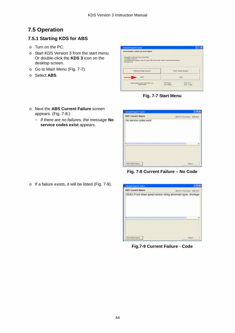
7.5 Operation7.5.1 Starting KDS for ABS
o Turn on the PC.o Start KDS Version 3 from the start menu.
Or double-click the KDS 3 icon on the desktop screen.
o Go to Main Menu (Fig. 7-7).o Select ABS.
Fig. 7-7 Start Menu
o Next the ABS Current Failure screen appears. (Fig. 7-8.)~ If there are no failures, the message No
service codes exist appears.
Fig. 7-8 Current Failure – No Code
o If a failure exists, it will be listed (Fig. 7-9).
Fig.7-9 Current Failure - Code
44

KDS Version 3 Instruction Manual
o After repairing the failure, restart KDS-ABS.
Fig. 7-10 will appear.
o Confirm No service codes exist, then select Intermittent failure to see if there are any codes.
Fig. 7-10 Current Failure
The ABS Intermittent failure screen will appear (Fig. 7-11).
Fig. 7-11 Intermittent Failure
o To erase the intermittent failure codes, select Erase Stored Service Codes (Fig. 7-11).
o Select Yes, then select OK (Fig. 7-12).
Fig. 7-12 Erase procedures
o Confirmation the ABS Intermittent failure has been erased is shown on screen (Fig. 7-13).
After confirming, select Return to finish.
Fig. 7-13 Erase Confirming
45
