kessel grease separator ‘se’ m ns 2, ns 4, ns 7, ns 10, 15 ... · installation, operating and...
TRANSCRIPT

INSTALLATION, OPERATING AND MAINTENANCE INSTRUTIONS
KESSEL Grease separator ‘SE’ M NS 2, NS 4, NS 7, NS 10, 15 and 20with manual waste disposal device
Edition 2012/07
Name / Signature Date Place
ID-Nr. 010-076
Subje
ct to
techn
ical a
mend
ment
Compact / Light weight foreasy shipping and handling
Frequent disposal of freshlycollected grease and sludgeinto connected storagetanks even during separatoroperation
Separate disposal / collec-tion of grease and sludge
Smooth wax-like surfaceprevents the building up tocoagulated oils and grease.
Company Stamp
KESSEL-Grease Separator „SE“ M NS 2, 4, 7, 10, 15 and 20 according to DIN 4040 and DIN EN 1825-1
The installation and service of this unit should be carried out by alicensed professional servicer
Product Advantages
2
Follow all local and national accident prevention regulations!
An electrical heating cable is located inside the heating cover!
It is FORBIDDEN to damage the heating cover by drilling, sawing, grinding it or sub-jecting it to any other process which takes away metal or by driving screws into it.
Disconnect the separator from its power source before carrying out maintenancework. During operation, maintenance or repair of the system, all DIN- / VDE- /DVGW norms and guidelines as well as any other appropriate local and national sa-fety regulations must be followed! The system is only designed to handle wastewaterfrom a kitchen with a maximum temperature of 60 deg Celsius. Higher temperaturescan result in damage to the system.
The motor protection relay on the rinsing motor and the internal temperature control-ler of the mixing motor automatically reactivate after turning off once the motor hascooled.
The grease / water mixture in the plant may become very hot. Please use appropria-te care during all work on the system.
CAUTION – risk of slippingDuring disposal, cleaning or maintenance, grease or water may spill on the floor ofthe operating area causing a very slippery surface.
No part of the plant should be stepped on.The plant is not to be climbed on as a means of reaching other installations.Use separate ladders etc. for this purpose.
Because of the possible formation of bio gasses, SMOKING IS PROHIBITED whilethe separator is open or the collection barrels are being exchanged.
Only operate the heater in the heating cover (filled with water or grease) when venti-lated.A pocket of air in the upper portion of the heating dome could cause the heatingdome to overheat due to the air pocket not allowing the heating cables to cool pro-perly.
No access for UNAUTHORISED PERSONSNo storing of foods (for reasons of hygiene)The operating area must be selected so that there is sufficient access around andabove the separator plant for disposal, cleaning and maintenance work.
Wastewater inside the separator can contain bacteria. All body parts (hands, fingers,etc.) which come in contact with the separator should be properly washed and disin-fected after the work is completed. Clothing coming in contact with the separator orwastewater should also be changed and washed accordingly.
When leaving the plant, always check the following:The discharge valves to the grease and sludge barrels must be closedThe rinsing-line valve must be open.The cover to the sludge trap must be tightly closedThe storage barrel lids must be screwed on tight.
Safety procedures / instructions concerning the separator must be familiar to all persons operating the separator!
1. Safety Instructions

Safety instructions ........................................................................................................Page 2
1. General ........................................................................................................Page 4
2. Installation 2.1 Installation instructions ....................................................Page 72.2 Assembly .........................................................................Page 82.3 Control unit mounting .......................................................Page 82.4 Installation example .........................................................Page 8
3. Commissioning 3.1 Placing separator into operating mode ............................Page 93.2 Instructions and hand-over ..............................................Page 93.3 Hand-over protocol ..........................................................Page 93.4 Filling ................................................................................Page 93.5 Ventilation .........................................................................Page 9
4. Operation 4.1 Control unit settings .........................................................Page 104.2 Operation..........................................................................Page 104.3 Functions / Steps of the disposal procedure ....................Page 104.4 Setting parameters ..........................................................Page 10
5. Disposal Disposal steps .................................................................Page 11
6. Explosion diagram ..........................................................................................Page 14
7. Control unit ..........................................................................................Page 16
8. Malfunctions and remedial measures ..........................................................................................Page 19
9. Accessories and replacement parts ..........................................................................................Page 21
10. Maintenance and servicing checks ..........................................................................................Page 22
11. Maintenance instructions for SE separators ..........................................................................................Page 22
12. Warranty ..........................................................................................Page 23
13. Declaration of Conformity ..........................................................................................Page 24
14. Manufacturer / Separator data and information .........................................................................................Page 25
15. Hand-over certificate ..........................................................................................Page 26
Table of contents
3
Dear customer,
We are pleased that you have chosen a KESSEL product.The entire system was subjected to a stringent quality control before leaving the factory. Nevertheless, please checkimmediately whether the system has been delivered to you complete and undamaged. In case of any transport da-mage, please contact the shipping company.Before the KESSEL ‘SE’ separator is installed and placed into operation, it is mandatory and in your own interest tocompletely read through and follow all the information contained in this Installation, Operation and Maintenance Manual.
KESSEL AG

4
1.1. Application
Oils and greases in wastewater are not allowed to be drai-ned into public wastewater pipes / sewers and also not intoto lakes / rivers. Oil and greases in wastewater pipes cancollect on the interior walls causing a reduction in the crosssectional area of the pipe and eventually pipe blockage. Inaddition, over time the collected grease begins to decompo-se and turn acidic which can lead to odour nuisances as wellas the corrosion / degradation of the drainage pipes and sy-stem.Without grease separators, the oils / greases will collect onthe surface of ponds / lakes as well as wastewater treatmentcollection ponds causing reduction of oxygen access tothese waters. DIN 1986 Part 1 requires that harmful sub-stances are retained. For this reason, grease separators inaccordance with DIN 4040 must be provided and the grea-se disposed of appropriately.
1.2. System Description
Separator functionThe special feature of the Type „SE“grease separator for self disposal ofwaste is its method of disposal.While conventional separators mustbe emptied completely and shutdown while this work is carried out,in the case of the „SE“, only the ma-
terial which has been separated out needs to be disposedand is drained off via discharge pipes into exchangeable bar-rels. The grease separator can be emptied any time withouthaving to interrupt the process. The separated material is insmaller quantities and is in a fresh state due to the fact thatthe sludge and grease is emptied multiple times per week.Barrels which have been filled are replaced with empty ones.Displaced air from the separation system is fed back into theseparator meaning that no problematic odours are releasedduring operation / disposal. If the grease solidifies, it can bereturned to a liquid state via the separator’s heated cover.During the heating process self cleaning takes place – as thegrease liquefies any particles / solids settles out of the grea-se layer and settle to the base of the tank. Sediments whichsettle out in the separator tank are pumped back to the slud-ge trap via a circulation system.
1. General
Inlet
Sludge storagetank
Grease storage tank
Outlet
Recycling
Disposal/

5
DIN 4040The KESSEL grease separators for the self disposal of waste„SE“ are designed in accordance with DIN 4040. The sludgetrap and grease separator are housed in different tanks. The vo-lumes, size of calming zones and shape of the installed units tosome extent exceed the specifications laid down in the norm /standard.
No external energy requirementsmeans that „SE“ grease se-parator plants operate without requiring an energy supply du-ring grease separation.
Reduced drinking water consumption and lower energycosts and wastewater fees, resulting from improved waterquality and possible re-utilisation of fresh grease, are the eco-nomical and ecological objectives. In accordance with the efflu-ent disposal regulations, the operator can put a higher priorityon re-utilisation than disposal.
No bad odoursIn the grease separator, the light substances, such as fats, oilsand floating sludge, accumulate on the surface and can be re-
moved via the grease discharge pipe. The heavier material sett-les out to the base of the sludge trap and is later drained intothe collection and transport barrels. Disposal of the material inclosed barrels is achieved with almost no smell. When changingthe barrels, there may be a temporary release of odours.
MaterialsSeries „SE“ KESSEL grease separator plants consist of a se-parate sludge trap and grease separator. The tanks, their inte-grated units and pipe work are all made from PE-HD. Thesmooth, wax-like surface of polyethylene hinders the build-upof deposits and solids and is therefore easy to clean. The plantsare fitted with odour-proof covers made from Duroplast 2K. Thefittings and units are resistant against corrosive / aggressivewastewaters and are designed for use in damp areas.
1. General
Dimensioned drawing and information table
Illustration shows an NS 2 separator
InletOutletSludge trapGrease separation areaCover with quick release clampHeating domeSludge storage barrelGrease storage barrelVentilationCleaning accessControl unitGrease mixing motor / leverRinsing pump
NS
24710
H18501850
L20002200
b10201300
B14001700
h114501450
h215701570
h3650730
Sludge trap
410 l410 l
Waste Contents
Grease trap
570 l1060 l
Weight – empty
200 kg260 kg
Weight – full
1200 kg1750 kg
see illustration1520
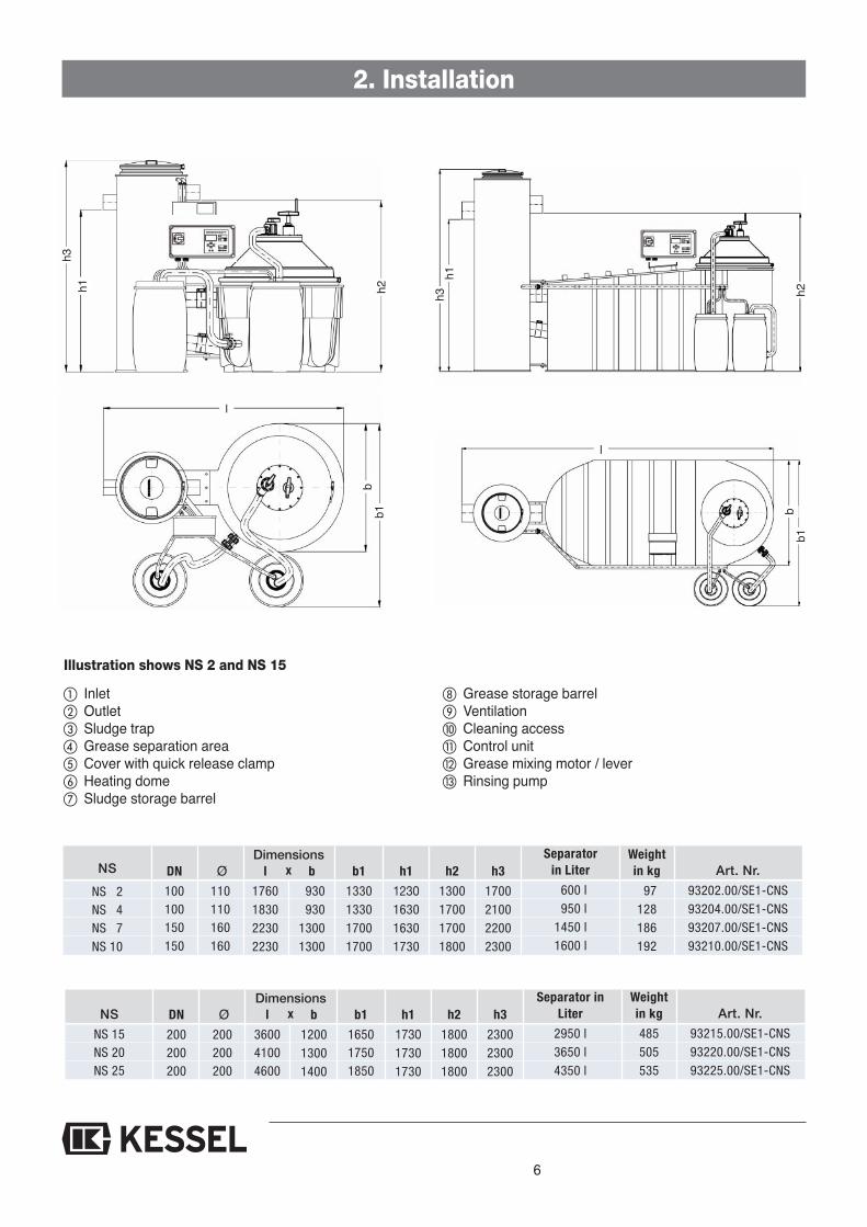
6
2. Installation
DN
100100150150
Ø110110160160
b
930930
13001300
h1
1230163016301730
h2
1300170017001800
h3
1700210022002300
l
1760183022302230
Separator in Liter
600 l950 l
1450 l1600 l
NS
NS 2NS 4NS 7NS 10
b1
1330133017001700
xDimensions
DN
200200200
Ø200200200
b
120013001400
h1
173017301730
h2
180018001800
h3
230023002300
l
360041004600
Separator inLiter
2950 l3650 l4350 l
NS
NS 15NS 20NS 25
b1
165017501850
xDimensions
Weightin kg
97128186192
Art. Nr.
93202.00/SE1-CNS93204.00/SE1-CNS93207.00/SE1-CNS93210.00/SE1-CNS
Weight in kg
485505535
Art. Nr.
93215.00/SE1-CNS93220.00/SE1-CNS93225.00/SE1-CNS
h3
l
h1 h2 h3h1
h2b
b1
bb1
l
Illustration shows NS 2 and NS 15
Inlet Outlet Sludge trap Grease separation area Cover with quick release clamp Heating dome Sludge storage barrel
Grease storage barrel Ventilation Cleaning access Control unit Grease mixing motor / lever Rinsing pump
7
2. Installation
2.1. Installation instructions
The grease separation plant is supplied complete in pre-as-sembled units. Under normal circumstances, the equipmentis set up by a plumber or can, if requested, be installed by aKESSEL technician for an agreed upon fee.
When installing the plant, the following must be observed 1. The safety instructions on Page 4 must be followed.2. The instructions on the packaging must be taken into ac-count! No non approved parts of the separator should beused to move or lift the separator during transport or instal-lation.
3. The grease separation plant must be checked for transportdamage immediately on arrival.
4. The technical data relating to your plant will be found on theserial plate on one of the tanks and the electrical data will befound on the serial plate attached to the control unit. All dataare recorded in these instructions as well the plant pass.Documents relating to the equipment are included at theback of the instructions.
5. Bad odours will be released if the plant or barrels are nothandled properly or maintenance work is not carried out inthe proper manner. For this reason, we recommend installingthe grease separator in a separate room with suitable venti-lation (such as a fan). It is also advisable to install the greaseseparator in a tiled room with at least one floor drain and ahot water supply in order to ease maintenance and cleaningwork. The height of the room must be sufficient for work tobe carried out at the maintenance ports (minimum 30 cmfrom the ceiling). The width of the room should allow for aworking space of about 1 m on all sides.
6. In the case of rooms with restricted access, the tanks can bedismantled and reassembled (see exploded diagram onPage 14).
7. Be sure that the maximum allowable floor loading in the roomof installation is not exceeded (see weight table).
8. The plant must be installed on a level surface in a frost freearea.
9. In order for the separator to function properly the tempera-ture in the room of installation should not be below 15 de-grees Celsius.
10. The service side is pre-assembled at the factory in accor-dance with the order. This can be altered on site. (See as-sembly instructions). Assemble the plant components usingthe connection elements supplied with the equipment.(Screw the tanks together using a maximum torque of 7Nm).
11. The inlet and outlet of the separator feed and discharge pipemust be connected on-site. Do this in accordance with thestandards DIN 1986.
12. The fall / drainage pipes to the inlet of the separator shouldhave at least a 1 meter long horizontal run with a slope of atleast 1:50 before entering the separator. The transition fromthe fall pipe to the calming stretch must be constructedfrom two 45 degree bends.
This reducesthe risk of the siphon and siphon trap being sucked empty.the amount of air admitted to the system, air movements andbuild-up of bad odours
the formation of foam in the separator.If the separator plant is installed below the local backwaterlevel, a wastewater lifting station must be installed in accor-dance with DIN 1986, providing local regulations do not requi-re otherwise. Lifting units must also be provided with their ownventilation pipe.
Important on-site requirements for proper function andodour free grease separator operation:Grease separator plants and their feed and discharge pipesmust be provided with sufficient ventilation in accordancewith DIN EN 1825-2. Consequently, as a ventilation pipe, thefeed must be taken above the roof. All pipes connected tothe plant that are more than 5 m long must be ventilated se-parately. If the main wastewater pipe to the separator is lon-ger than 10 m and not separately ventilated – then this pipemust also be ventilated.
In order to avoid the build up of bad odours, the feed and di-scharge pipe connections must be firmly connected and allseals must be fitted carefully.
All drainage fixtures connected to the grease separatorshould be equipped with odor traps and sludge traps. Largeitems such as utensils, ketchup / mustard wrappers andbones etc will cause the separator, pumps and valves to mal-function.
2.2 Assembly
1. Grease and sludge separator components
Set up the grease separator tank (10a) and the sludge separa-tor tank (11a)
Connect the drainage hoses (10b and 11b) to the sludge dis-posal port (4a) and to the grease disposal port (6a)
Connect the ventilation hoses (10c and 11c) to the connectionport on the sludge and grease storage barrel covers
8
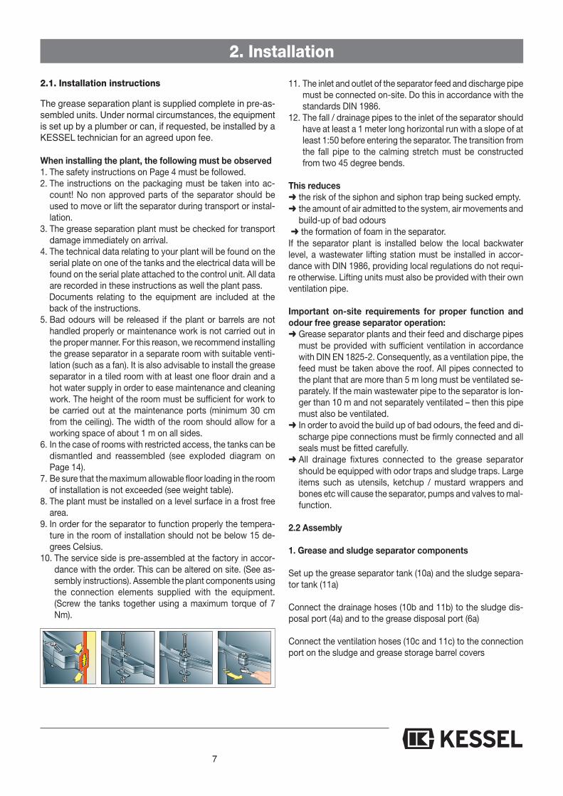
2. Installation
2.4 Installation example
KESSEL SE M NS 2grease separatorSludge trapSludge storage barrelGrease storage barrelSampling chamberKESSEL basementdrain ‘The Universal’with integrated twinbackwater flapsKESSEL Aqualift S Duolifting station
ProductAccessoriesSourced on-site
2.2.1 AnschließenConnect the inlet and the outlet of the grease separator to theon-site drainage pipes as well as connecting the main drai-nage pipe to a ventilation pipe.
2.2.2 Checks
All pipe, hose and storage barrel connections must be checkedto assure that they are watertight. The manual disposal valvesmust be placed in the base position meaning:- Sludge and grease disposal valves in the closed posi-tion (4a, 6a)
- Rinsing valve between grease and sludge separationareas in the open position
Grease sepa-rator ventilation
Ventilation pipes should beconnected directly to outdoorambient air (roof). The venti-lation pipes should not beconnected to one another.
2.3 Control unit mountingThe main power switch must be placed in the 0 position inorder to open the control unit. Use the included mountingtemplate in order to drill four holes in the wall – the includeddowels and screws should be used for mounting the controlunit to the wall. The control unit should be mounted in a frostfree area and not in direct sunlight. It should also be placed
in a position so that the cover can be completely opened toallow full access into the control unit.
Inlet
Wastewater from the grease se-parator which is collected belowthe public sewer level should bepumped with a twin pump liftingstation. The pressure disposalpipe should be plumbed abovethe local backwater level andthen drained with gravity into thepublic sewer (this prevents anybackwater from disturbing theoperation of the lifting station).
Public sewer
9
3. Commissioning
3.1 Placing separator into operation mode
Before allowing wastewater from the kitchen to enter theseparator make sure the following is done:
- Interior of separator as well as the inlet and outlet arecompletely cleaned and free of any debris
- Completely fill the separator with cold mains drinkingwater – until water flows out of the outlet.
- Check the entire separator and all pipe / hose connec-tions to assure they are watertight. Also assure that theseparator was not damaged during shipping or installa-tion.
- Check all pipes for watertightness by conducting a:- Visual inspection- Pressure test
3.2 Instructions and hand-overThe commissioning and initial grease separator training isnormally handled by a KESSEL customer service represen-tative.
1. The following persons should be present during the grea-se separator commissioning- Plumber- Representative of the building owner
Also recommended to be present- Person who will be responsible for the operation of the
separator- Grease separator disposal company
2. Preparation for the hand over and initial training- All sanitary connections must be complete- Completely filling the separator with cold mains drinking
water- The disposal company must be arranged to be present
during the first disposal
3. Instructions- Information concerning the disposal- Practical training of the separator operation- Function check of the separator- Instructions on how often the grease separator should
be disposed
4. Hand-over of the installation and operational manual
5. After the initial training has been completed, the separa-tor should be returned to normal operational mode – mea-ning the separator must be filled with clean cold mainsdrinking water
3.3 Hand over protocol (see attachment)
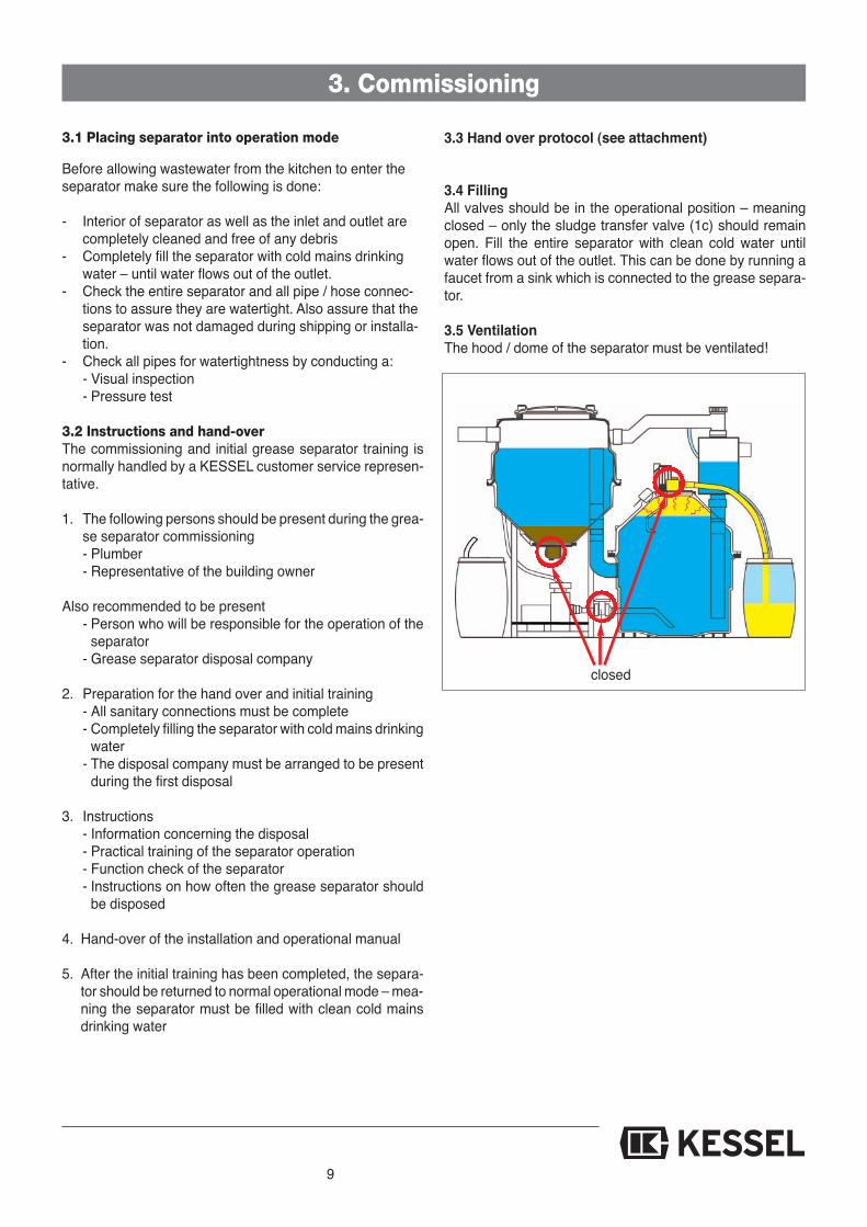
3.4 FillingAll valves should be in the operational position – meaningclosed – only the sludge transfer valve (1c) should remainopen. Fill the entire separator with clean cold water untilwater flows out of the outlet. This can be done by running afaucet from a sink which is connected to the grease separa-tor.
3.5 VentilationThe hood / dome of the separator must be ventilated!
closed

10
4.1 Control unit settings
4.1.1 GeneralThe following functions are controlled by the control unit:- Rinsing (Euro Norm grease separators do not have the rin-
sing function.)- Heating- MixingThese functions are automatically started and ended accor-ding to the programmed settings. The system’s componentscan also be operated manually by using the control unit (SeeMenu 2.1)
4.1.2 Programming the functionsThe time of day, date and disposal program has been factoryset.
4.2 OperationThe control unit has a ‘Start’ and ‘Stop’ button (5) for ma-nually controlling the disposal and a button for acknowled-ging any alarms (3). The current operating status of the se-parator is displayed by an LED (1), an alarm / malfunctionLED (2) and a function LED (4). The control unit can be ope-rated by using the ‘Up’, ‘Down’, ‘ESC’ and ‘OK’ buttons (7).
Please follow the operating manual (8). Before conductingany work on the control unit be sure to disconnect it from itspower source (9) (see safety instructions).
4.3 Functions / Steps of the disposal procedure
The control unit is set up for automated or manual operation.Manual operation has the priority over automated operation. Ifmanual operation is activated, the automated operation is de-
activated (internally set automated procedures will not start!)
Note: For proper disposal of collected grease, the heating fun-ction should be run for at least 2 hours before disposal. Duringthe last minute of heating, the mixing motor should also run.If the automated heating times are changed, the mixingtimes should be changed accordingly.
4.4 Setting parametersNote: When programming the heating / mixing times be surethat no times run into the next day. For example if heatingbegins at 22:00 it should end at 23:59.
Setting the heating timesIn Menu Section 3.1.1 the day on which heating shouldoccur can be set. Also here the starting time of the heatingand the duration of the heating can be set.
Setting the mixing function
Note: When programming the heating / mixing times be sure thatno times run into the next day. For example if heating begins at22:00 it should end at 23:59.
Setting the rinsing functionIn Menu 3.1.3 on the control unit the day of the week that rinsingshould take place can be set. Here you can also set the time ofday that the rinsing should begin and also the duration of the rin-sing.
4. Operation
➀
➂
➄
➃
➅➆➇➈
Operation – LED Alarm-LED Alarm – button Pump operation – LED START/STOP Digital Display
Navigation buttons‘Up/down’ + ‘ESC/OK’
Operating instructions Disconnect control unit
from power
➁
0 System info 1 Information
2 Maintenance
3 Settings
2.1 Manual operation
2.2 Automated operation
2.3 SDS (Self Diagnosis System)
2.4 Service dates
2.5 Activating the Remote Control
3. Settings 3.1 Parameters 3.1.1.1 Every day
3.1.1.2 Monday
3.1.1.8 Sunday
3.1.1. ...........
3.1.1 Heating
3. Settings 3.1 Parameters 3.1.2 Duration3.1.2 Mixing
3. Settings 3.1 Parameters 3.1.3.1 Every day
3.1.3.2 Monday
3.1.3.3 ..........
3.1.3.8 Sunday
3.1.3 Rinsing

11
The aim of re-utilising grease requires frequent waste dis-posal from the grease separator in order to keep the bio-chemical decomposition process to a minimum. The di-scharge of separated material must therefore be carried outnot only according to quantity but also according to time - atleast twice per week. The volume of the grease separator inthe case of NS 2 is 80 litres and in the case of NS 4, it is 160litres in accordance with the Standard. The collection barrelholds approx. 60 litres.
Failure-free and proper operation of the plant isonly guaranteed if the waste from the plant is dis-posed of in time.
For the flow chart of the separation operation, see Sec-tion 2.
A brief set of instructions in which the most importantfunctions are explained are attached to the control unit.
Step 1: Rinsing During the rinsing process, the sediments are transferred fromthe grease separator into the sludge trap and grease films andfloating sludges are conveyed from the sludge trap into thegrease separator.
Warning:The sludge trap must be filled to the overflow level. The rin-sing process must not be started immediately after sludge di-scharge otherwise the grease-separation area will be pum-ped out!Too frequent or too slow sludge transfer can cause the grea-se separator area to be pumped out
Automatic rinsingAutomatic rinsing is triggered via a time switch. For this rea-son, leave the valve on the rinsing line (1c) open during nor-mal operation of the grease separator. In order to check thatthe pump is operating properly, rinsing should be carried outbriefly by hand once per month during waste disposal.Whether the pump is delivering or not can be established bythe noise of liquid running into the sludge trap.
Manual rinsing The valve on the rinsing line (1c, page 14)) must be
open (standard position) Start the pump in the manual mode (Control Unit Menu
Section 2.1)
Step 2: Grease disposal Disposal should take place at the end of the programmedheating times.
Heating times can be customer set (see time settings in Sec-tion 4.4) in order to better match the operation to on-site re-quirements
At the end of the set heating time (set at 2 hours at the fac-tory), slowly open the grease discharge valve (6a, page 14).Observe the flow of grease through the transparent fillinghose (10b, page 14).
Drain the grease and any floating sludge into the grease sto-rage barrel until either the barrel (F) is full (which can be de-tected when no more grease is capable of flowing into thebarrel) or until grease is no longer visible in the transparenthose (10b, page 14). Now close the grease disposal valve(6a, page 14).
5. Disposal
Disposal Steps
S
C
FA
B
G
E
S
C
FA
B
E
G

In the case that no grease flows out into the collection barrel,the heating duration must be extended, until the hardenedgrease turns liquid. Depending on the room temperature andthe amount of grease this heating could me more than twohours. On the control unit display the heating mode is dis-played. The internal temperature sensor regulates the hea-ting until the programmed heating time has elapsed. The startand stop of the heating dome occurs automatically.
In the case that no grease drains into the grease collectionbarrel:a) The amount of water in the separator is not sufficient to
create enough pressure to push out the grease. In thiscase a drainage fixture connected to the grease separa-tor (kitchen sink for example) should be run to allow morewater into the separator
b) If there is still hardened grease in the separator. The dis-posal intervals should be shortened (draining of greaseand sludge should take place more frequently)
Step 3: Sludge disposal
Slowly open the valve (4a, page 14) of the sludge trap (C).Observe the sludge draining through the transparent hose(11b, page 14) into the sludge collection barrel. Close thesludge drainage valve as soon as the amount of drainingsludge decreases noticeably or if the sludge barrel is full (S).
Note: Make sure to check the following when the disposalprocess has ended:- All valves are in the basic setting (closed) – except for therinsing valve (1c, page 14) which should remain in the openposition.- The heating (B) is off- The pump (P) is off
Step 4: Collection barrel exchange
Note: close valves and follow all safety instructions!
Prepare an empty collection barrel and remove its cover. Di-sconnect the drainage pipe and ventilation pipe from thecollection barrel and unclip the quick release clamp. Slowlyremove the cover from the full tank (any remaining fluid in thedrainage will have enough room in the collection tank) andplace onto the empty barrel and connect.
Place the closed cover onto the full collection barrel and se-cure properly. Mark the barrel to identify the contents (‘Grea-se’ or ‘Sludge’). We recommend changing the barrels at alater to date to allow them to cool and settle – preferably whenthe next disposal takes place. During this time the grease cansettle to the top of the collection barrel and any water cansettle to the bottom. This will aide in the reduction of odourswhen exchanging barrels.
Note:- In the case that the collection barrels are so full that sludge
or grease backs up into the transparent hoses then it is im-portant to change the barrel´s immediately to prevent anyblockage from building up in the hoses.
- Store all full barrels in a cool and frost free area.- Collection barrels which are full should be taken off site as
soon as possible. If stored too long, and depending on thetemperature of the storage room, the contents of the bar-rels can begin to decompose causing gas build up whichcan result in gases / odours escaping from the barrels.
- In the case that a disposal company handles the removal ofthe barrels, make sure that any replacement barrels sup-plied to you by the disposal company are the same size asthe original barrels and have an original KESSEL cover.
Tips on reducing odour build up1. When exchanging barrels to it cleanly and quickly.2. Make sure that the barrels covers are properly secured.3. Any spilled wastewater should be quickly cleaned up.4. Any filled or partially filled storage barrels (depending on
room temperature) should be removed from site at a ma-ximum within 4 weeks. It is recommended that the barrelsare stored in a very cool (frost free) area.
The decomposition process in the collection barrels resultsin gas build up inside the barrels which can cause them tobulge and release bad smelling odours. By continuous odourproblems please see Section ‘Malfunctions and RemedialMeasures’.
5. Disposal
S
C
G
FA
B
E
P
12
13
5. Disposal
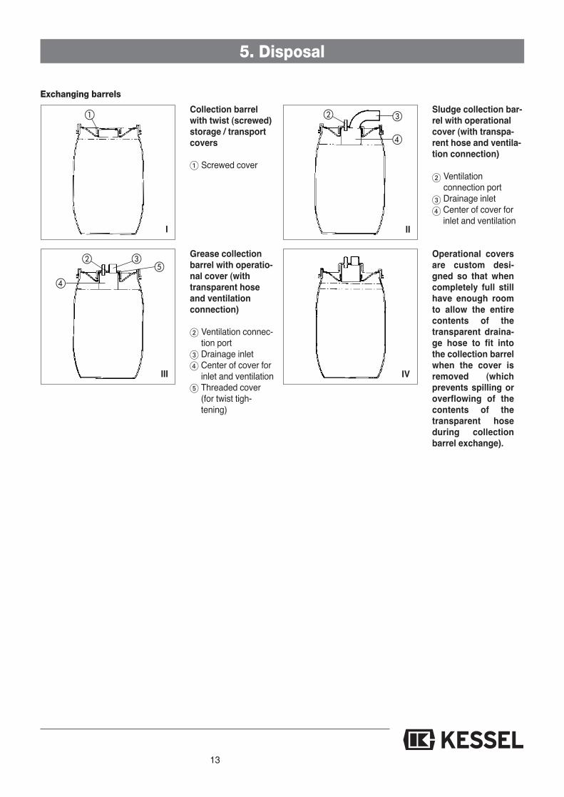
Collection barrelwith twist (screwed)storage / transportcovers
Screwed cover
Sludge collection bar-rel with operationalcover (with transpa-rent hose and ventila-tion connection)
Ventilation connection portDrainage inletCenter of cover forinlet and ventilation
Grease collectionbarrel with operatio-nal cover (withtransparent hoseand ventilationconnection)
Ventilation connec-tion portDrainage inletCenter of cover forinlet and ventilationThreaded cover(for twist tigh-tening)
Operational coversare custom desi-gned so that whencompletely full stillhave enough roomto allow the entirecontents of thetransparent draina-ge hose to fit intothe collection barrelwhen the cover isremoved (whichprevents spilling oroverflowing of thecontents of thetransparent hoseduring collectionbarrel exchange).
Exchanging barrels
I
III
II
IV
6. Explosio
1a 1b 1c
3a
3b
4a4b
3c
5a
2a
2b2c
6a
9a
9b
9c9d
2f
2e
2d
11a
11b
11c
11d
14

15
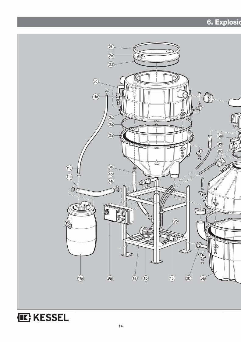
Lower framePump rinsing systemRinsing system valve
Base section of sludge trapTank seal / gasketUpper section of sludge trapCover sealSludge trap coverQuick release clasp
Rinsing line hoseRinsing line stubExchange stub
Sludge discharge valveSludge discharge cover
Lower section of grease separatorTank seal / gasketHeating dome
Grease discharge valveMixerGrease discharge coverCover seal / gasket
Compensation tank
Ventilation pipe
Control unitPump cablesHeating dome cablesMixer cables
Grease collection barrelFilling hoseVentilation hose
Sludge collection barrelFilling hoseVentilation hoseExchange stub
1a1b1c
2a2b2c2d2e2f
3a3b3c
4a4b
5a5b5c
6a6b6c6d
7
8
9a9b9c9d
10a10b10c
11a11b11c11d
on diagram
5b
5c
6b
6c6d
7
8
10a
10b
10c
ill. shows NS 2

16
7. Control unit
Control unit picture / Control unit ID sticker description
Control unit ID sticker description
Control unit type Control unit article number Connection voltage and frequency Current range Protection class (IP) Control unit serial number Control unit replacement part number Danger symbol Protection category CE symbol Disposal information – do not dispose of
control unit in household trash Control unit hardware id
The control unit IDsticker is located onthe right narrow side ofthe control unit
ill. 1
ill. 2
Outputs
Potential free contact • changeover contact,center contact, closingcontact, open Contact
• max. 42 VAC / 0,5 A Optional: Remote • Connection contacts speaker alarm for remote speaker(Artikel-Nr. 20162) alarm

17
7. Control unit
HeizhaubeHeating mantle
1000 ± 10 Ω bei 25°
≤ 0,4 Ω
40 ± 5Ω bei 25°
Anschlußbelegung an Pos.11Wiring at Pos. 11
Erdung / Grounding
↔
↔
↔
Erdung / Grounding
TemperaturfühlerTemperature probe
TemperatursicherungThermal fuse
HeizwicklungHeating coil
TemperaturfühlerTemperature probe
TemperatursicherungThermal fuse
HeizwicklungHeating coil

18
Electrical information:
No heating rod
230V single phase, 50 HzConnection jacksMains switch on control unit
Power supplyConnectionPower supply disconnection
Connection values
Protection classFusingOn-site RCD
Max. 2430 Watt when connec-ting:
Heating dome: 230 V singlephase, 50 Hz, 1200 Watt
Mixing motor: 230 V singlephase, 50 Hz 180 Watt
Rinsing motor: 230 V singlephase, 50 HZ, max 750 Watt
IP 54C 16 AFI 30 mA
Max. 3630 Watt whenconnecting:Heating dome: 230 V singlephase, 50 Hz, 1200 WattMixing motor: 230 V singlephase, 50 Hz 180 WattRinsing motor: 230 V singlephase, 50 HZ, max 750 WattHeating rod: 230 V singlephase, 50 Hz, max 1500 Watt
IP 54C 16 AFI 30 mA
230V single phase, 50 HzConnection jacksMains switch on control unit
Single heating rod
Max. 5130 Watt when connec-ting:Heating dome: 230 V singlephase, 50 Hz, 1200 WattMixing motor: 230 V singlephase, 50 Hz 180 WattRinsing motor: 230 V singlephase, 50 HZ, max 750 WattHeating rods: 230 V singlephase, 50 Hz, max 1500 Watt
IP 54C 16 AmpFI 30 mA
400V 3 - phase, 50 HzConnection jacksMains switch on control unit
Twin heating rods
7. Control unit
19
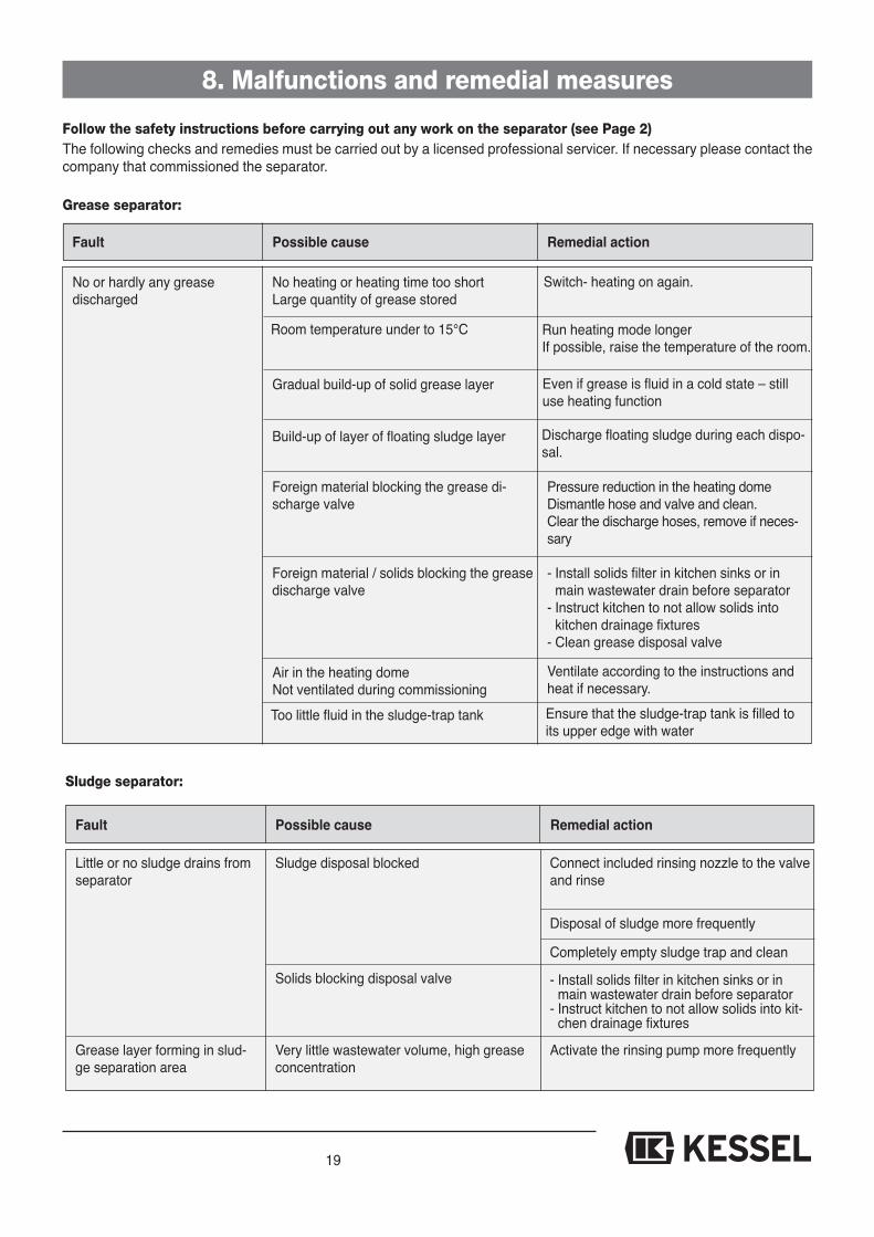
Follow the safety instructions before carrying out any work on the separator (see Page 2)
8. Malfunctions and remedial measures
The following checks and remedies must be carried out by a licensed professional servicer. If necessary please contact thecompany that commissioned the separator.
Grease separator:
Fault Possible cause Remedial action
Pressure reduction in the heating dome Dismantle hose and valve and clean.Clear the discharge hoses, remove if neces-sary
- Install solids filter in kitchen sinks or inmain wastewater drain before separator
- Instruct kitchen to not allow solids into kitchen drainage fixtures
- Clean grease disposal valve
Foreign material blocking the grease di-scharge valve
Foreign material / solids blocking the greasedischarge valve
Air in the heating domeNot ventilated during commissioning
Ventilate according to the instructions andheat if necessary.
Too little fluid in the sludge-trap tank Ensure that the sludge-trap tank is filled toits upper edge with water
Build-up of layer of floating sludge layer Discharge floating sludge during each dispo-sal.
Gradual build-up of solid grease layer Even if grease is fluid in a cold state – stilluse heating function
Room temperature under to 15°C Run heating mode longerIf possible, raise the temperature of the room.
No heating or heating time too shortLarge quantity of grease stored
Switch- heating on again.No or hardly any grease discharged
Sludge separator:
Fault Possible cause Remedial action
Connect included rinsing nozzle to the valveand rinse
Disposal of sludge more frequently
Completely empty sludge trap and clean
Activate the rinsing pump more frequentlyVery little wastewater volume, high greaseconcentration
- Install solids filter in kitchen sinks or inmain wastewater drain before separator
- Instruct kitchen to not allow solids into kit-chen drainage fixtures
Solids blocking disposal valve
Sludge disposal blockedLittle or no sludge drains fromseparator
Grease layer forming in slud-ge separation area
19

20
8. Malfunctions and remedial measures
Pump:
Fault Possible cause Remedial action
Run the disposal pump – after approx 1 mi-nute the pump begins moving fluid again
Caution: only allow a licensed professionalto handle this repair!
Disconnect control unit from its power sour-ce. Change the electrical connection toallow for proper pump rotation.
Caution: pump can activate at any time ifpump cools!
Air in pump
Pump jammed or pump interior area blocked
Rotation of pump wrong
Pump is overloaded, or very high sludgecontent in pumping medium
Pump does not pump anyfluid
Pump’s internal thermalbreaker activates (automati-cally shuts off pumps)
Permanent odor problems:
Fault Possible cause Remedial action
Check to ensure all drainage pipes andgaskets are properly connected and in proper operating condition
Install ventilation pipe or increase size ofexisting ventilation pipe
Check barrels, barrel covers and pipeconnections to barrelsCheck all hoses and hose connectionsRemove full storage barrels from room soo-nerLifting station (which may be connected tooutlet of grease separator) not properly ven-tilatedInstall ventilation / fresh air supply to roomwhere separator is located.
Drainage pipes
Ventilation pipe missing or ventilation pipesize too smallStorage barrels and connections
HosesFull storage barrels not removed in timelyfashion (contents begin to decompose)Lifting station
Room where separator is installed has clo-sed walls and no or improper ventilation
Odor problems
Disconnect control unit from its power sourceRemove motor’s cover and turn motor shaftIf the motor is still jammed, close valve nearpump, open the access to the pump’s impel-ler and clean impeller / pump area. Note thatcontents of the sludge disposal pipe will drainout.
21
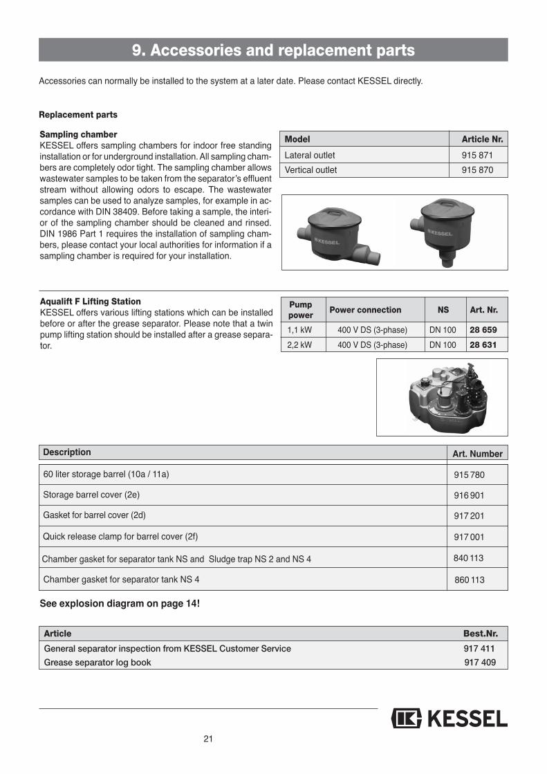
Accessories can normally be installed to the system at a later date. Please contact KESSEL directly.
9. Accessories and replacement parts
Replacement parts
Description Art. Number
840 113
860 113
915 780
916 901
917 201
917 001
Chamber gasket for separator tank NS and Sludge trap NS 2 and NS 4
Chamber gasket for separator tank NS 4
See explosion diagram on page 14!
60 liter storage barrel (10a / 11a)
Storage barrel cover (2e)
Gasket for barrel cover (2d)
Quick release clamp for barrel cover (2f)
Article Best.Nr.
General separator inspection from KESSEL Customer Service 917 411
Grease separator log book 917 409
1,1 kW 400 V DS (3-phase) DN 100 28 659
2,2 kW 400 V DS (3-phase) DN 100 28 631
PumpPower connection NS Art. Nr.
power
Aqualift F Lifting StationKESSEL offers various lifting stations which can be installedbefore or after the grease separator. Please note that a twinpump lifting station should be installed after a grease separa-tor.
Model Article Nr.
Lateral outlet 915 871Vertical outlet 915 870
Sampling chamberKESSEL offers sampling chambers for indoor free standinginstallation or for underground installation. All sampling cham-bers are completely odor tight. The sampling chamber allowswastewater samples to be taken from the separator’s effluentstream without allowing odors to escape. The wastewatersamples can be used to analyze samples, for example in ac-cordance with DIN 38409. Before taking a sample, the interi-or of the sampling chamber should be cleaned and rinsed.DIN 1986 Part 1 requires the installation of sampling cham-bers, please contact your local authorities for information if asampling chamber is required for your installation.

22
10. Maintenance and servicing checks
Follow all safety instructions!
10.1 Maintenance
The grease separator should be inspected every 6 months bya professional.Along with the disposal of the separator, the following workshould also be completed:- The interior walls of the grease and sludge tanks should beinspected- The electrical systems and parts of the grease separatorshould be checked- All work completed on the separator should be entered in thelog book
All mechanical and electrical parts such as the pump, valves,closure valves, control unit etc. should be inspected every 6months according the manufacturer’s instructions.
10.2 General Inspection
Before commissioning and then in regular intervals thereafter(but at a minimum every 5 years) the separator must be fullyinspected by a licensed professional to assure all systems arein proper working order. Prior to this inspection the separatorshould be fully emptied and cleaned. Included in this generalinspection is the following:
- Required size of the grease separator should be checked toassure that the installed separator meets the requirements- Condition and watertightness of the separator should bechecked
- Interior walls of all components and any electrical systemsshould be checked- Assure that a proper ventilation pipe is connected near theseparator’s inlet (this ventilation pipe should be connectedto ambient air – to the roof)- Review the separator’s log book to make sure all log bookentries seem plausible and accurate- Check to assure that all grease and sludge taken from theseparator has been properly handled / disposed.- Assure that all required certifications and documents forthe separator are available (drainage plan, authorizati-ons, user’s manual)
The results of the general inspection should be documented.Any irregularities, defects or problems with the separatorshould also be documented and repaired immediately.
11. Maintenance instructions for SE separators Maintenance instructions for KESSEL ‚SE’ grease sepa-rators
The person carrying out maintenance must be familiar withthe operation of the plant.A spare gasket for the heating cover of the corresponding„SE“ plant should be taken to the site so that this can bechanged if necessary.When opening the grease separator, bad odours must be ex-pected.
Preparation1.) It must be ensured that no waste water runs into the grea-se separator during maintenance work (inform the ope-rator).
2.) Dispose of grease and sludge in accordance with theoperating instructions (abide by the heating times).
Maintenance work on the sludge trap1.) Open the cover to the sludge trap and remove all thewater from inside (e.g. by having it pumped out by aneffluent disposal company).
2.) Check the sludge discharge valve for obstructions, cleanthe inner discharge area and remove any possible block-ages caused by larger objects.
3.) Wash down the inner walls of the sludge trap with warmclarified water, free them from any contamination and de-posits and clean them.
4.) Check the feed to the sludge trap for obstructions anddeposits and clean if necessary.
5.) Check the outlet of the rinsing line and clean if necessary.
Maintenance work on the grease separator tank1) Pump the water from the grease-separator tank to thesludge trap using the rinsing pump until the sludge trap iscompletely full.
2.) WARNING: Isolate the control box from the power supp-ly before starting work.The electrical heating cover can now be removed. Inorder to do this, release the electrical plug connection(s),the transparent hose and the heating cover fasteners. Re-move the heating cover.
3.) Have the residual water pumped out by, for example, aneffluent-disposal company.
23
12. Warranty
1. In the case that a KESSEL product is defective, KESSEL hasthe option of repairing or replacing the product. If the productremains defective after the second attempt to repair or repla-ce the product or it is economically unfeasible to repair or re-place the product, the customer has the right to cancel theorder / contract or reduce payment accordingly. KESSELmust be notified immediately in writing of defects in a product.In the case that the defect is not visible or difficult to detect,KESSEL must be notified immediately in writing of the defectas soon as it is discovered. If the product is repaired or re-placed, the newly repaired or replaced product shall receivea new warranty identical to that which the original (defective)product was granted. The term defective product refers onlyto the product or part needing repair or replacement and notnecessarily to the entire product or unit. KESSEL products arewarranted for a period of 24 month. This warranty period be-gins on the day the product is shipped form KESSEL to its cu-stomer. The warranty only applies to newly manufacturedproducts. Additional information can be found in section 377of the HGB.
In addition to the standard warranty, KESSEL offers an addi-tional 20 year warranty on the polymer bodies of class I / IIfuel separators, grease separators, inspection chambers, wa-stewater treatment systems and rainwater storage tanks. Thisadditional warranty applies to the watertightness, usabilityand structural soundness of the product.A requirement of this additional warranty is that the product isproperly installed and operated in accordance with the validinstallation and user's manual as well as the correspondingnorms / regulations.
2. Wear and tear on a product will not be considered a defect.Problems with products resulting from improper installation,handling or maintenance will also not be considered a defect.
Note: Only the manufacturer may open sealed components orscrew connections. Otherwise, the warranty may become nulland void
01.06.2010
11. Maintenance instructions for SE separators
4.) Wash down the inside of the grease separator tank andthe heating cover with warm clarified water and cleanthem, carefully removing any deposits that may be there.
5.) Flush through the transparent hoses with warm water andclean them.
6.) Clean the pipe connections between the sludge trap andthe grease separator tank, rinse and clean the dischargevalves, rinse pump and special covers for the disposalbarrels and check for obstructions.
7.) Check the heating cover seal for any possible damageand exchange if necessary. Clean and grease the surfa-ce of the seals and reinstall the heating cover.
8.) Reassemble the plant.
Maintenance work on the rinsing pump1.) Shut off the rinsing system valve, release the electricalplug connection and place a flat container underneath tocatch the water from the rinsing line.
2.) Slacken the screwed fasteners in the feet of the motorand remove the impeller pump.
3.) Clean the impeller and free the pump from any blockagesthat may be there.
4.) Reassemble the pump, open the valve and check that thepump is operating properly (check flow).
Additional commentsIf a sampling chamber has been installed, clean the interiorand remove any debris.
Carry out maintenance on the lifting station in accordancewith the manufacturer’s installation instructions. Warm wateris recommended when cleaning the lifting station.
Re-commissioning the grease separator1.) Check the whole separator system for leaks.2.) Re-start the KESSEL „SE“ grease separator plant in ac-cordance with Section 5.1.
24
EU-KONFORMITÄTSERKLÄRUNG EC declaration of conformity/ Déclaration CE de conformité
Nach der Maschinenrichtlinie 2006/42/EG, der Niederspannungsrichtlinie 2006/95/EG, Richtlinie der elektromagnetischen Verträglichkeit 2004/108/EG und Bauproduktrichtlinie 89/106/EWG / According to the Machine Guidelines 2006/42/EG, the Low Voltage Guidelines 2006/95/EG, Electromagnetism Guidelines 2004/108/EG and in accordance with Directive 89/106/EEC / Selon les directives mécaniques 2006/42/EG, les directives de basse tension 2006/95/EG, les directives pour la compatibilité électromagnétique 2004/108/EG et les directives de construction 89/106/EWG Hiermit erklären wir, / Herewith we declare, / Par la présente, nous déclarons,
est conforme à la norme EN 1825-1:2004 et p
figurent sur la plaquette d´identification selon l
M E. Thiemt L Vorstand
Managing Board R C
EU- ONFKO
ÄRLRKESTÄTIMRO
GUNÄR
EC
MredhcNaagnmortekel
nihcaMethsenilediGu
seuqinacméétilibitapmco
älkretimreHi
EU ONFKOfnocfonoitaralced
/24/6002einilthcirnenihcsaMagn 002tiekhcilägrtreVnehcsiet
senilediuGe GE/42/2006 , GE108/04/20 idn a ccan
s GE/42/2006 vticeridsel, euqiténgamorcteléé 108/2004
alcedwehtiwerHe/rwinerä
ÄRLRKESTÄTIMROnoitaralcéD/ytimrof
rsgnunnapsredeiNred,GE/dnuGE8/014/0 B rtdukoaupr
egatloVwoLeth nilediGu98evitceriDh tiwecnadroc
edsev onienstesbas 2006GE/108 t e ocedseivtceirdsle
dsuonetnesérpalraP/era
GUNÄRétimrofnocedE Cn
GE/59/6002einilthcir thciR, ci eniilht GWE106/89/ / ocAc
sen GE/95/2006 amotrcelE, /CEE/610/9 dselnolSe
GE/95/2006 sevticeridsel, GWE/601/98noitcurtsno
snoralcéd
é
redeiniltotgnidro
msitengasevitceridalruop
älkretimreHi
alcedwehtiwerHe/,rwinerä
dsuon,etnesérpalraP/,era
,snoralcéd
Separator characteristics
Thisunith
asbeen
checkedf
orwa
tertightn
esstob
esuretha
titisfullyop
eration
albe
forelea
vingthe
factor
y.
Date
Name
ofexam
iner
Mat.-D
escription
Mat.-N
o./Order-No./Prod.Da
te
Ref.N
o./Material/W
eight
EN/App
roval
Dimen
sions
Volum
e
Density
Description1
Description2
25
26
15. Hand-over certificate
Separator Type: __________________________________________________________
Day / Hour __________________________________________________________
Project description /Building services supervisor __________________________________________________________Address __________________________________________________________Telephone / Fax __________________________________________________________
Builder __________________________________________________________Address __________________________________________________________Telephone / Fax __________________________________________________________
Planner __________________________________________________________Address __________________________________________________________Telephone / Fax __________________________________________________________
Contracted plumbing company __________________________________________________________Address __________________________________________________________Telephone / Fax __________________________________________________________
KESSEL-Commissions no.:System operator /owner __________________________________________________________Address __________________________________________________________Telephone / Fax __________________________________________________________
User __________________________________________________________Address __________________________________________________________Telephone / Fax __________________________________________________________
Person of delivery __________________________________________________________
Other remarks __________________________________________________________
The system operator, and those responsible, were present during the commissioning of this system.
____________________________ ____________________________ ____________________________Place and date Signature owner Signature user

27
15. Hand-over certificate
Handover certificate (copy for the company carrying out the installation) The initial operation and instruction was carried out in the presence of the person authorised to perform the
acceptance and the system operator.
The system operator/person authorised to perform the acceptance was informed about the obligation to ser-vice the product according to the enclosed operating instructions.
Initial operation and instruction were not carried out.
The client/ person responsible for initial operation was handed the following components and/or product components
Initial operation and instruction is being carried out by (company, address, contact, phone)
The exact coordination of the dates for initial operation/instruction is being carried out by the system operator and per-son responsible for initial operation.
Place, date Signature of person Signature of system operator Signature of the companyauthorised to perform acceptance carrying out the installation work

Backwater protection Lifting Stations and pumps Drains and shower channels Separators
-Grease Separators-Oil- /Fuel-/CoalescenceSeparators-Starch Separators-Sediment Separators
Septic Systems Inspection Chambers Rainwater Management
Systems