kfg; kfgs; kfgc (can bus) en assembly instructions · kfg; kfgs; kfgc (can bus) en for industrial...
TRANSCRIPT

ENKFG; KFGS; KFGC (CAN bus) for industrial use
Assembly instructions acc. to EC Dir. 2006/42/ECfor partly completed machinery with associated operating instructions
Version 02

Page 2 EN Notes
Masthead
These original assembly instructions with as-
sociated operating instructions according to EC
Machinery Directive 2006/42/EC are an inte-
gral part of the described product and must be
kept for future use.
These original assembly instructions with as-
sociated operating instructions have been pre-
pared in accordance with the established stan-
dards and rules for technical documentation,
VDI 4500 and EN 292.
© SKF Lubrication Systems Germany GmbH
This documentation is protected by copyright.
SKF Lubrication Systems Germany GmbH re-
serves all rights, including those to the photo-
mechanical reproduction, duplication, and dis-
tribution by means of special procedures (e.g.,
data processing, data media, and data net-
works) of this documentation in whole or in
part.
Subject to changes in contents and technical
information.
Service
If you have technical questions, please contact
the following addresses:
SKF Lubrication Systems Germany GmbH
Berlin Plant
Motzener Strasse 35/37
12277 Berlin
Germany
Tel. +49 (0)30 72002-0
Fax +49 (0)30 72002-111
www.skf.com/lubrication
Hockenheim Plant
2. Industriestrasse 4
68766 Hockenheim
Germany
Tel. +49 (0)62 05 27-0
Fax +49 (0)62 05 27-101
www.skf.com/lubrication
Page 3 ENAssembly instructions table of contents
Assembly instructions table of contents
EC Declaration of Incorporation 6
Explanation of symbols and signs 7
1. Safety instructions 9
1.1 Intended use 9
1.2 Authorized personnel 9
1.3 Electric shock hazard 10
1.4 System pressure hazard 10
1.5 Compressed air hazard 10
1.6 Hydraulic pressure hazard 10
1.7 Explosion protection information 11
2. Lubricants 12
2.1 General information 12
2.2 Selection of lubricants 12
2.3 Approved lubricants 13
3. Overview 15
4. Assembly 16
4.1 General information 16
4.2 Setup and attachment 16
4.2.1 Assembly holes 18
4.2.2 Mounting dimensions 18
4.3 Pump elements 19
4.3.1 KFG/KFGS pump elements 19 4.3.2 KFGC (CAN bus) pump elements 19
4.3.3 Installing a pump element 19
4.3.4 Deliverable pump elements 20
4.3.5 Pressure regulating valve 21
4.4 Instructionsonlubricantilling 22
4.4.1 Lubricantilling 22 4.4.2 Filler coupling 23
4.4.3 Filling cylinder 23
4.4.4 Filling cover 23
4.5 Electrical connection 24
4.5.1 General conditions for electrical connections 24
4.5.2 KFG series 25
4.5.2.1 Power supply 12/24 VDC 25
4.5.2.2 Power supply 90-264 VAC 25
4.5.2.2 External control 26
4.5.2.4 Fill level monitoring 26
4.5.2.5 Pressure relief valve with integrated pressure regulating valve 30
4.5.3 KFGS series 31
4.5.3.1 Power supply 12/24 VDC 31
Settings for progressive lubrication 32
4.5.3.2 Counter operation without system monitoring 32
4.5.3.3 Counter operation without system monitoring 33
4.5.3.4 Counter operation with system monitoring (progressive) 33
Settings for single-line lubrication 34
4.5.3.5 Timer operation without system monitoring 34
4.5.3.6 Timer operation with system monitoring (single-line centralized lubrication system) 34
4.5.3.7 Power supply 12/24 VDC using a cubical plug 35
4.5.3.8 12/24 VDC connections for system monitoring using an
M12x1 circular plug socket 36
4.5.3.9 Timer operation without system monitoring(andilllevelcontrol) 36 4.5.3.10 Timer operation with system monitoring(andilllevelcontrol) 36 4.5.4.1 Pressure relief valve with integrated pressure regulating valve 37
4.5.5 KFGS 90-264 VAC series with integrated control unit 38
4.5.5.1 Power supply 90-264 VAC 38
4.5.5.2 Connections for system monitoring 39
4.5.5.3 Timer operation without system monitoring(andilllevelcontrol) 39 4.5.5.4 Timer operation with system monitoring(andilllevelcontrol) 39 4.5.6 KFGC series 40
4.5.6.1 Power supply 12/24 VDC 40
4.5.6.2 Connectivity for KFGC series 42
4.5.6.3 Example of CAN bus control with 5/4 directional solenoid valve 44
4.5.6.4CANbussystemconiguration with connection to CAN bus system 44
4.5.6.5CANbussystemconigurationwithout connection to CAN bus system 44
4.6 Fill level control 45
4.7 Progressive system ventilation 45
4.8 Single-line system ventilation 45
4.9 Note on the rating plate 46

Page 4 EN Operating instructions table of contents
1. Safety instructions 48
2. Lubricants 48
3. Transport, delivery, and storage 49
3.1 Lubrication units 49
3.2 Electronic and electrical devices 49
3.3 General notes 49
4. Assembly 50
4.1 Information on assembly 50
4.2 Assembly procedure for KFG (S) (C) pump units 50
4.3 Dismantling and disposal 50
5 Design 51
5.1 General information 51
5.2 Design 51
5.2.1 Pump housing 51
5.2.2 Lubricant reservoir 51
5.2.3 KFGS control unit 51
5.3 KFG pump units 52
5.4 KFGS pump units 52
5.5 KFGC (CAN bus) 53
5.6 Images of pump units 54
6. Functional description in progressive systems 55
6.1. Functional description in progressive systems with KFG pump unit 55
Operating instructions table of contents
6.1.1 Pump element 55
6.1.2 Pressure regulating valve 55
6.2. Functional description in progressive systems with KFGS pump unit 56
6.3. Functional description in progressive systems with KFGC (CAN bus) pump unit 57
6.3.1 Explanations of the lubrication process and lubrication cycle 57
6.3.2 Modes of operation 59
6.3.2.1 Automatic control 59
6.3.2.2 Semi-automatic control 60
6.3.2.3 Control via CAN commands 60
6.3.3 Monitoring functions 61
6.3.3.1 System monitoring 61
6.3.3.2 Fill level monitoring 61
6.3.3.3 Monitoring lubrication cycle via piston detector 62
6.3.3.4 Monitoring signal cables for cable breakage and monitoring valves and piston detectors 62
6.3.3.5 Monitoring switching outputs for short circuits 63
6.3.3.6 Monitoring power consumption of the pump motor 63
6.3.3.7 Monitoring unit temperature 64
6.3.4 Display and documentation functions 64
6.3.5 Conigurableparameters 64
7. Functional description in single-line systems 65
7.1 Functional description of single-line systems with KFG pump unit 65
7.1.1 Pump element 65
7.1.2 Pressure regulating valve 65
7.1.3 Pressure relief valve 65
7.2 Functional description of single-line systems with KFGS pump unit 66
7.3. Functional description in single-line systems with KFGC (CAN bus) pump unit 67
7.3.1 Systems with directional solenoid valves 67
7.3.2 Multiple lubrication zones 67
7.3.3 Control unit 68
7.3.3.1 Modes of operation 69
7.3.3.2 Semi-automatic control 70
7.3.3.3 Control via CAN commands 70
7.3.4 Monitoring functions 71
7.3.4.1 Fill level monitoring 71
7.3.4.2 Pressure build-up monitoring 71
7.3.4.3 Pressure reduction monitoring 72
7.3.4.4 Monitoring signal cables for cable breakage and monitoring
valves and pressure switches 72
7.3.4.5 Monitoring switching outputs for short circuits 2
7.3.4.6 Monitoring power consumption of the pump motor 72
7.3.4.7 Monitoring unit temperature 72
Page 5 ENOperating instructions table of contents
7.3.5 Display and documentation functions 73
7.3.6 Conigurableparameters 738. Commissioning 74
8.1 General commissioning 74
9. Display and control elements of control screen 75
9.1 KFGS series 75
9.1.1 Three-digit LED display 76
9.1.2 LED display 78
9.1.3 Pushbutton operation 79
9.2 KFGC (CAN bus) series 80
10. KFGS display mode 82
10.1 KFGS series 82
11. KFGS programming 84
11.1 Start programming mode 84
11.2 Change lubrication interval times 84
11.3 Coniguresystemmonitoring 86 11.4 Change operating modes 87
11.5 Change access code 88
11.6 Programming ranges 89
11.7 Display ranges 89
12. KFGS operating modes 90
12.1 Timer operation 90
12.2 Counter operation 90
12.3 No system monitoring 90
12.4 With system monitoring 90
12.5 Fill level monitoring 91
12.6 Monitoring via piston detector 91
12.7 Monitoring via pressure switch 92
13. Shutdown 93
13.1 Temporary shutdown 93
13.2 Permanent shutdown 93
14. Maintenance 94
14.1 General information 95
14.2 Service 95
15. Operational and pump faults 97
15.1 KFGS operational malfunctions 97
15.1.1 General 97
15.1.2 Display faults 97
15.1.3 Deletefaultnotiication 97 15.1.4 Fault types 98
15.1.5 Recording fault times 99
15.1.6 Maintenance and repair 99
15.1.7 Malfunctions on pump unit in progressive system 100
15.1.8 Malfunctions on KFG/KFGS pump units 101
15.2 Operational malfunctions on KFGC (CAN bus) 103
15.2.1 Pump malfunctions 103
15.2.2 Faults detected by control unit 103
15.2.3 Fault types 103
15.2.4 Faultnotiication 103 15.2.5 Read faults 103
15.2.6 Remedy faults 103
15.2.7 Warning and malfunction indicator on KFGC (CAN bus) pump unit 105
16. Technical data 107
17. Accessories 111
17.1 Connectivity for timer operation
withsystemmonitoring,illlevel control, piston detector and indicator light 112

Page 6 ENK
FG
C
EC Declaration of Incorporation according to Machinery Directive 2006/42/EC, Annex II Part 1 B
The manufacturer SKF Lubrication Systems Germany GmbH ,Plant Hockenheim, 2. Industriestraße 4, DE - 68766 Hockenheim hereby declares that the partly completed machinery:
Designation: Piston pump aggregate for industrial application
Type: KFG, KFGS, KFGC
Part no.: KFG*; KFG*M*; KFG*R*; 772-*
Year of construction: See type identification plate
complies with the following basic requirements of the EC Machinery Directive 2006/42/EC at the time when first being launched in the market.
1.1.2 · 1.1.3 · 1.3.2 · 1.3.4 · 1.5.1 · 1.5.6· 1.5.8 · 1.5.9 · 1.6.1 · 1.7.1 · 1.7.3 · 1.7.4
The special technical documents were prepared following annex II part B of this directive. Upon justifiable request, these special technical documents can be forwarded electronically to the respective national authorities. The person empowered to assemble the technical documentation on behalf of the manufacturer is the head of stan-dardization; see manufacturer‘s address.Furthermore, the following directives and harmonized standards were applied in the respective applicable areas:2011/65/EU RoHS II 2014/30/EU Electromagnetic compatibility | Industry
Standard Edition Standard Edition Standard Edition Standard Edition
DIN EN ISO 12100 2011 DIN EN 60947-5-1 2010 DIN EN 61000-6-2 2006 DIN EN 61000-6-4 2011
DIN EN 809 2012 DIN EN 61131-2 2008 Amendment 2011 DIN EN 60947-5-1 2010
DIN EN 60204-1 2007 Amendment 2009 DIN EN 61000-6-3 2011
Amendment 2010 DIN EN 60034-1 2015 Amendment 2012
DIN EN 50581 2013 DIN EN 61000-6-1 2007
The partly completed machinery must not be put into service until the final machinery into which it is to be incorporated has been declared in conformity with the provi-sions of the EC Machinery Directive 2006/42/EC and any other applicable directives.
Hockenheim, 2016/05/31
Jürgen Kreutzkämper Manager R&D GermanySKF Lubrication Business Unit
Stefan Schürmann Manager R&D Hockenheim/Walldorf SKF Lubrication Business Unit
EC Declaration of Incorporation
KFG
KFG
SK
FG
KFG
SK
FG
C

Page 7 EN
Informational symbolsIndicators used with safety instructions
and their signiicanceHazard symbols
Explanation of symbols
Explanation of symbols and signs
You will find these symbols, which warn of
specific dangers to persons, material assets, or
the environment, next to all safety instructions
in these operating instructions.
Please heed these instructions and proceed
with special care in such cases. Please forward
all safety instructions to other users.
General hazard DIN 4844-2-W000
Electrical voltage/current
Hot surface
Indicator Use
Danger! danger of bodily injury
Warning! danger of damage to property and the environment
Note Provides additional information
Note
Prompts an action
Used for itemizing
Points out other facts, causes, or consequences
Provides additional information
Instructions placed directly on the machines/
grease lubrication pump units, such as:
Arrow indicators
Labelsforluidconnectionsmust be followed and kept in fully legible
condition.
You are responsible!
Please read the assembly and operating in-
structions thoroughly and follow the safety
instructions.
Danger of being drawn into machinery
DIN 4844-2-W008
DIN 4844-2-W026
BGV 8A
Slipping hazardDIN 4844-2-W028
Warning of potentially explosive atmosphereDIN 4844-2-W021
Page 8 EN
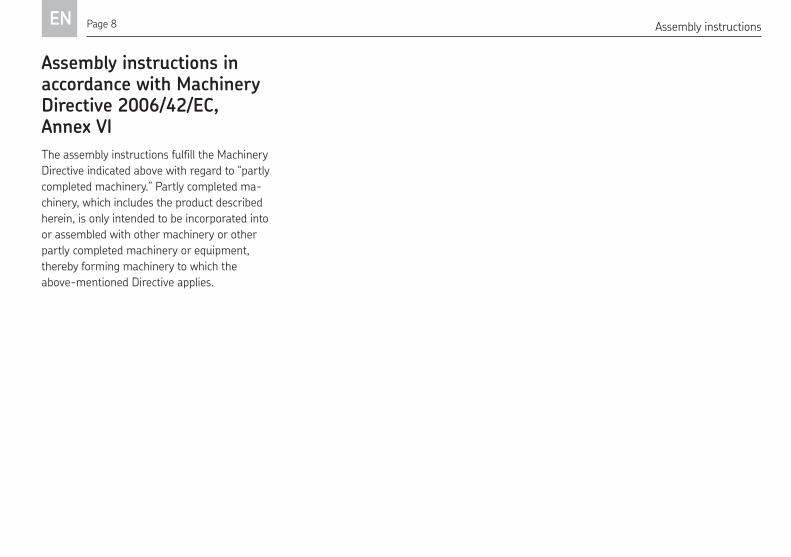
Assembly instructions in accordance with Machinery Directive 2006/42/EC, Annex VI
The assembly instructions fulfill the Machinery
Directive indicated above with regard to “partly
completed machinery.” Partly completed ma-
chinery, which includes the product described
herein, is only intended to be incorporated into
or assembled with other machinery or other
partly completed machinery or equipment,
thereby forming machinery to which the
above-mentioned Directive applies.
Assembly instructions
Page 9 EN
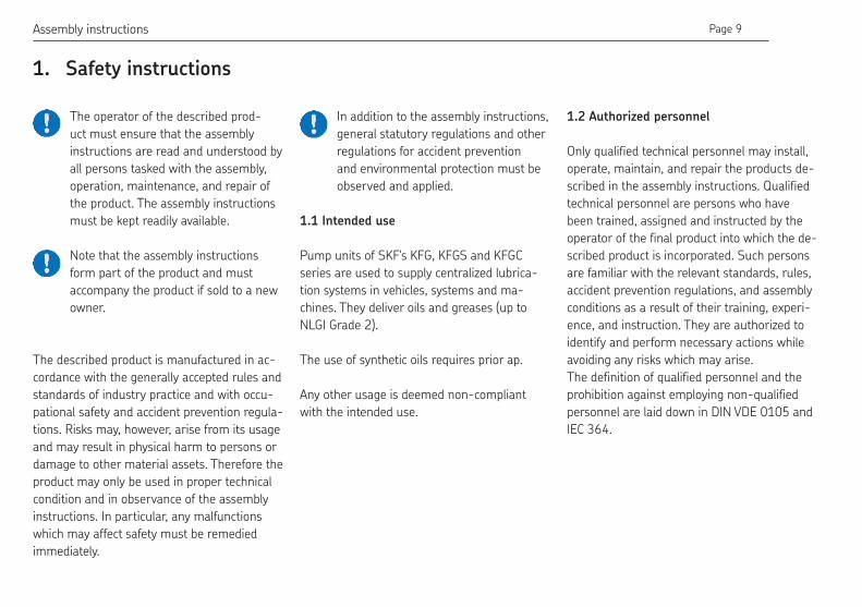
The operator of the described prod-
uct must ensure that the assembly
instructions are read and understood by
all persons tasked with the assembly,
operation, maintenance, and repair of
the product. The assembly instructions
must be kept readily available.
Note that the assembly instructions
form part of the product and must
accompany the product if sold to a new
owner.
1. Safety instructions
In addition to the assembly instructions,
general statutory regulations and other
regulations for accident prevention
and environmental protection must be
observed and applied.
1.2 Authorized personnel
Only qualified technical personnel may install,
operate, maintain, and repair the products de-
scribed in the assembly instructions. Qualified
technical personnel are persons who have
been trained, assigned and instructed by the
operator of the final product into which the de-
scribed product is incorporated. Such persons
are familiar with the relevant standards, rules,
accident prevention regulations, and assembly
conditions as a result of their training, experi-
ence, and instruction. They are authorized to
identify and perform necessary actions while
avoiding any risks which may arise.
The definition of qualified personnel and the
prohibition against employing non-qualified
personnel are laid down in DIN VDE 0105 and
IEC 364.
The described product is manufactured in ac-
cordance with the generally accepted rules and
standards of industry practice and with occu-
pational safety and accident prevention regula-
tions. Risks may, however, arise from its usage
and may result in physical harm to persons or
damage to other material assets. Therefore the
product may only be used in proper technical
condition and in observance of the assembly
instructions. In particular, any malfunctions
which may affect safety must be remedied
immediately.
1.1 Intended use
Pump units of SKF's KFG, KFGS and KFGC
series are used to supply centralized lubrica-
tion systems in vehicles, systems and ma-
chines. They deliver oils and greases (up to
NLGI Grade 2).
The use of synthetic oils requires prior ap.
Any other usage is deemed non-compliant
with the intended use.
Assembly instructions

Page 10 EN
1.4 System pressure hazard
Lubrication systems are pressurized
during operation. Centralized lubrication
systems must therefore be depressur-
ized before starting assembly, main-
tenance or repair work, or any system
modiicationsorsystemrepairs.1.5 Compressed air hazard
The described product is pressurized
during operation. The product must
therefore be depressurized before
starting assembly, maintenance or re-
pairwork,oranysystemmodiicationsor system repairs.
Depending on the model design, the product
may be able to be operated with compressed
air. Through the use of the appropriate com-
pressed air quality class, compressed air prep-
aration can be optimized and machine down-
time and higher maintenance costs avoided.
The compressed air to be used here must
complywithatleastqualityclass5asdeinedby ISO 8573-1:
Max. particle size 40 μm
Max. particle density 10mg/m³
Pressure dew point 7°C
Water content max. 7800 mg/m³
Residual oil content max. 25 mg/m³
1.6 Hydraulic pressure hazard
The described product is pressurized
during operation. The product must
therefore be depressurized before
starting assembly, maintenance or re-
pairwork,oranysystemmodiicationsor system repairs.
Depending on the model design, the product
may be able to be operated hydraulically.
1.3 Electric shock hazard
Electrical connections for the described product
may only be established by qualified and
trained personnel authorized to do so by the
operator, and in observance of the local condi-
tions for connections and local regulations
(e.g., DIN, VDE). Significant bodily injury and
property damage may result from improperly
connected products.
Danger!
Work on products that have not been
de-energized may result in bodily injury.
Assembly, maintenance and repair work
may only be performed on products
that have been de-energized by
qualiiedtechnicalpersonnel.Thesupply voltage must be switched off
before opening any of the product's
components.
Assembly instructions
Page 11 EN
1.7 Explosion protection information
Danger!
Only the pump models tested and
approved by SKF Lubrication Systems
Germany GmbH in accordance with
ATEX Directive 2014/34/EU are permit-
ted to be used in areas with explosion
protection. The relevant class of protec-
tion is engraved on the pump's rating
plate.
Whenillinglubricantintothepump, make sure the lubricant is clean. The
reservoirmustbeilledingoodtime(payattentiontoilllevelmonitoring).LubricantmustbeilledonlyviatheillersocketG 3/8“ (FF) or G 1/2“ (FB) on the pump
lange.Lubricantmayonlybeilledviathe "reservoir cover" if absolutely certain
that no potentially explosive atmosphere
exists.
Incaseofoverilling,theexcessive amount of lubricant must be removed.
Make sure there is no potentially explosive
atmosphere when doing this.
Theswitchingcircuitsoftheilllevelmonitor must be supplied by an intrinsi-
cally safe circuit, e.g., through the installa-
tion of an ATEX-compliant isolating switch
by the customer.
The unit must be grounded via a ground
connection. The customer must install ad-
equate overload protection for the power
consumption of the motor.
To avoid electrostatic discharge, lay
hydraulic connecting lines in corrosion-
resistant metal tubing, e.g., stainless
steel pipe.
When setting up the pump, make sure the
setup location is level and not subject to
vibrations or jolts.
During maintenance work, use only tools
intended for use in potentially explosive
spaces or else make certain that there is
no potentially explosive atmosphere
present.
The service life of the oil lubrication pump
is limited. It must therefore undergo a
function and leak test at regular intervals.
Perform appropriate repairs in the event
of malfunctions, leaks, or rust. Replace the
pump if necessary.
The user must make sure through the
choice of the lubricant to be delivered that
no chemical reactions capable of serving
as ignition sources will occur in conjunc-
tion with the explosive atmospheres
expected.
The lubricant’s ignition temperature has
to be at least 50 kelvin above the pump’s
maximum surface temperature (tempera-
ture class).
Assembly instructions

Page 12 EN
2. Lubricants
2.1 General information
All products from SKF Lubrication
Systems Germany GmbH may be used
only for their intended purpose and in
accordance with the information in the
product's assembly instructions.
Intended use is the use of the products for the
purpose of providing centralized lubrication/
lubrication of bearings and friction points using
lubricants within the physical usage limits
which can be found in the documentation for
the devices, e.g., assembly instructions/operat-
ing instructions and the product descriptions,
e.g., technical drawings and catalogs.
Particular attention is called to the fact that
hazardous materials of any kind, especially the
materials classified as hazardous by CLP
Regulation EC 1272/2008 may only be used to
fill SKF centralized lubrication systems and
components and delivered and/or distributed
with the same after consulting with and re-
ceiving written approval from SKF.
No products manufactured by SKF Lubrication
Systems Germany GmbH are approved for use
in conjunction with gases, liquefied gases,
pressurized gases in solution, vapors, or such
fluids whose vapor pressure exceeds normal
atmospheric pressure (1013 mbar) by more
than 0.5 bar at their maximum permissible
temperature.
Other media which are neither lubricant nor
hazardous substance may only be fed after
consultation with and written approval from
SKF Lubrication Systems Germany GmbH.
SKF Lubrication Systems Germany GmbH con-
siders lubricants to be a component of the sys-
tem design which must be factored into the
selection of components and the design of
centralized lubrication systems. The lubricating
properties of the lubricants are critically im-
portant in these considerations.
2.2 Selection of lubricants
Observe the instructions from the
machine manufacturer regarding the
lubricants that are to be used.
Warning!
The amount of lubricant required at
alubricationpointisspeciiedbythebearing or machine manufacturer. It
must be ensured that the required
quantity of lubricant is provided to the
lubrication point. The lubrication point
may otherwise not receive adequate
lubrication, which can lead to damage
and failure of the bearing.
Selection of a lubricant suitable for the lubrica-
tion task is made by the machine/system man-
ufacturer and/or the operator of the machine/
system in cooperation with the lubricant supplier.
The bearings/friction points that require lubri-
cation, their expected load during operation,
and the expected ambient conditions are taken
into account during selection, with consider-
ation of economic and environmental aspects.
Assembly instructions

Page 13 EN
2.4 Lubricants and the environment
Warning!
Lubricants can contaminate soil and
bodies of water. Lubricants must be
properly used and disposed of. Observe
the local regulations and laws regarding
the disposal of lubricants.
It is important to note that lubricants are envi-
ronmentally hazardous, flammable substances
which require special precautionary measures
during transport, storage, and processing.
Consult the safety data sheet from the lubri-
cant manufacturer
SKF Lubrication Systems Germany
GmbH supports customers in the selec-
tion of suitable components for feeding
the selected lubricant and in the plan-
ning and design of a centralized lubri-
cation system.
Please contact SKF Lubrication Systems
Germany GmbH if you have further questions
regarding lubricants. Lubricants can be tested
in the company's laboratory for their suitability
for pumping in centralized lubrication systems
(e.g., "bleeding").
You can request an overview of the lubricant
tests offered by SKF Lubrication Systems
Germany GmbH from the company's Service
department.
2.3 Approved lubricants
Warning!
Only lubricants approved for the prod-
uct may be used. Unsuitable lubricants
can lead to failure of the product and to
property damage.
Warning!
Different lubricants cannot be mixed, as
mixing may result in damage and ne-
cessitate costly and complicated clean-
ing of the product/lubrication system.
It is recommended that an indication of
the lubricant in use be attached to the
lubricant reservoir in order to prevent
accidental mixing of lubricants.
The product described here can be operated
using lubricants that meet the specifications in
the technical data. Depending on the product
design, these lubricants may be oils, fluid
greases, or greases.
Oils and base oils may be mineral, synthetic,
and/or rapidly biodegradable. Consistency
agents and additives may be added depending
on the operating conditions.
Note that in rare cases, there may be lubri-
cants whose properties are within permissible
limit values but whose other characteristics
render them unsuitable for use in centralized
lubrication systems. For example, synthetic lu-
bricants may be incompatible with elastomers.
Assembly instructions

Page 14 EN
for information regarding transport, storage,
processing, and environmental hazards of the
lubricant that will be used.
The safety data sheet for a lubricant can be re-
quested from the lubricant manufacturer.
2.5 Lubricant hazards
Danger!
Centralized lubrication systems must al-
ways be free of leaks. Leaking lubricant
is hazardous due to the risk of slipping
and injury. Be mindful of any lubricant
leaking out during assembly, operation,
maintenance, and repair of centralized
lubrication systems. Leaks must be
sealed off without delay.
Lubricant leaking from centralized lubrication
systems is a serious hazard. Leaking lubricant
can create risks that may result in physical
harm to persons or damage to other material
assets.
Warning!
Follow the safety instructions on the
lubricant's safety data sheet.
Lubricants are a hazardous substance. The
safety instructions on the lubricant's safety
data sheet must be followed. The safety data
sheet for a lubricant can be requested from the
lubricant manufacturer.
Assembly instructions

Page 15 EN
12 53 4
6 7 86
3
KFGC(CAN-Bus)
KFG KFGS
1
5 21
5
43
6 9
10
4
7
3. Overview
Components
Item Description Chapter
1 Assembly holes 4.2.1
2 Lubricant reservoir 4.2.2
3 Pump elements 4.3.
4 Pressure regulating valve 4.3.5
5 Conical head nipple 4.3.5
6 Electrical connection 4.5
7 General control unit Operating CAN bus display instructions
8 Pushbuttons Operating instructions
9 Inputs and outputs Operating (CAN bus version) instructions
10 CAN bus plug Operating instructions
Components
without control
with control
with CAN bus control
Assembly instructions

Page 16 EN
4. Assembly
4.1 General information
Pump units of the KFG, KFGS and KFGC (CAN
bus) series are an integral component of cen-
tralized lubrication systems used in machines
and systems.
They deliver greases up to NLGI Grade 2. The
pump units differ in terms of lubricant reser-
voir capacity, lubricant filling, control and func-
tion monitoring. The installation of volume-
specific pump elements permits a single unit
of the KFG or KFGS series to operate up to
three independent zones.
The KFGC series is capable of operating up to
four independent zones, depending on the
task. The system can be equipped with or
without functionality to monitor pressure
build-up and reduction.
4.2 Setup and attachment
The pump unit should be installed in a place
protected from contamination, water splashes
and vibrations. It should, however, be easily
accessible so that all other installations can be
performed without difficulty and the device can
be filled easily.
The fill level of the reservoir must be easily
visible.
The unit is mounted in a vertical position.
Any assembly holes must be made according
to the diagram on the following page.
Design specifications and conditions of the
manufacturer and the object must be observed
when installing the pump unit.
A drilling jig can be ordered (order number
951-130-115).
During assembly and especially when drilling,
always pay attention to the following:
Existing supply lines must not be damaged
by assembly work.
Other units must not be damaged by
assembly work.
The product must not be installed within
range of moving parts.
The product must be installed at an
adequate distance from sources of heat.
Maintain safety clearances and comply
with local regulations for assembly and
accident prevention.
On the pump units' electrical connections, en-
sure that appropriate measures prevent inter-
ference between signals due to inductive, ca-
pacitive or electro-magnetic couplings.
Shielded cables must be used in places where
electrical interference fields can distort signal
transmissions despite separate laying of
cables.
KFG
SK
FG
KFG
CAssembly instructions

Page 17 EN
The rules and empirical values for
"EMC-compliant" cabling must be taken into
consideration.
Warning!
When drilling the assembly holes, you
must be careful of any supply lines or
other units, as well as of other hazards
such as moving parts.
Maintain safety clearances and comply
with local regulations for assembly and
accident prevention.
Warning!
Do not tilt the KFG (S) (C) grease
lubrication pump unit!
The pump units are installed on the machine
using three M8 screws with a minimum length
of 20 mm.
Fastening material to be provided by the
customer:
Hexagon head screws (3x) per
DIN933-M8x....-8.8
Washers (3x) per DIN 125-B8.4-St
Warning!
The torque of the fastening screws
depends on the customer’s installation.
Make sure that torque is adequate
when installing the pump unit!
KFG
SK
FG
KFG
C
Assembly instructions
Page 18 EN
D
C
A
B
min
max
E
E
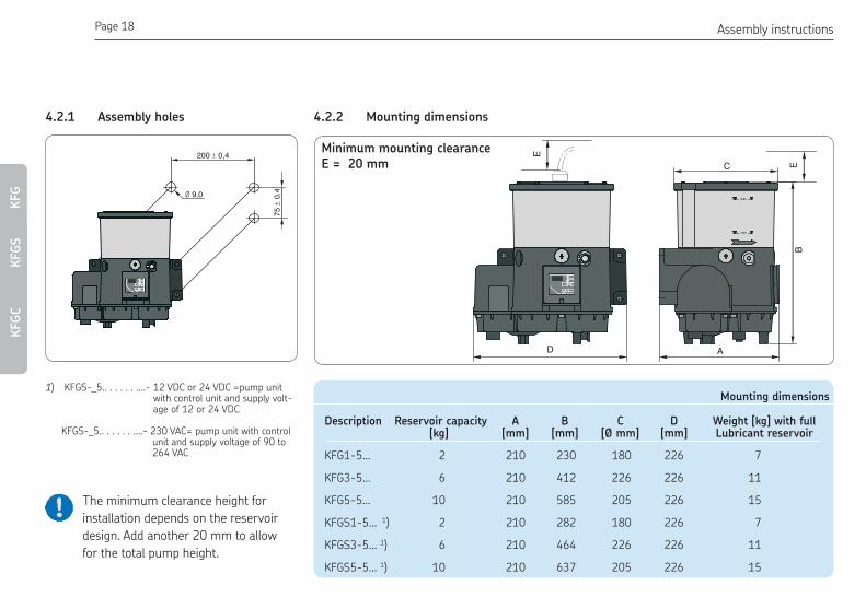
Mounting dimensions
Description Reservoir capacity A B C D Weight [kg] with full [kg] [mm] [mm] [Ø mm] [mm] Lubricant reservoir
KFG1-5... 2 210 230 180 226 7
KFG3-5... 6 210 412 226 226 11
KFG5-5... 10 210 585 205 226 15
KFGS1-5... 1) 2 210 282 180 226 7
KFGS3-5... 1) 6 210 464 226 226 11
KFGS5-5... 1) 10 210 637 205 226 15
75
0,4
±
200 0,4±
Ø 9,0
4.2.1 Assembly holes 4.2.2 Mounting dimensions
1) KFGS-_5.. . . . . . ....- 12 VDC or 24 VDC =pump unit with control unit and supply volt-age of 12 or 24 VDC
KFGS-_5.. . . . . . ....- 230 VAC= pump unit with control unit and supply voltage of 90 to 264 VAC
Minimum mounting clearanceE = 20 mm
The minimum clearance height for
installation depends on the reservoir
design. Add another 20 mm to allow
for the total pump height.
KFG
SK
FG
KFG
CAssembly instructions

Page 19 EN
4.3 Pump elements
4.3.1 KFG/KFGS pump elements
KFG and KFGS pump units can be equipped
with up to three pump elements. Each pump
element has a connector for, e.g., connecting
an independent progressive feeder. A grease
return can be attached in place of a pump
element.
Close any outlets which are not required using
a DIN 910-M20x1.5-5.8 screw plug with a
DIN 7603-A20x24-Al washer.
The pump elements must be ordered accor-
ding to the required delivery rate.
4.3.2 KFGC (CAN bus) pump elements
3/2 directional control valves can be employed
so that lubricant connections can also return
the lubricant into the reservoir from lubricant
outlets which are not required at the moment.
Close any outlets which are not required using
a DIN 910-M20x1.5-5.8 screw plug with a
DIN 7603-A20x24-Al washer.
4.3.3 Installation of a pump element
Pump units of the KFG, KFGS und KFGC
(CAN bus) series are generally delivered with
pump elements installed.
Perform the following to later add or replace a
pump element:
• Turn off pump unit.
• Loosen and remove screw plug.
12
3
Pump element replacement
Then perform the following:
• Loosen and remove pressure regulat-
ing valve (2) (or lubrication line (3)) on an
already mounted pump element (1).
• Loosen and remove mounted pump ele-
ment (1).
• Insert new pump element (1) into housing
hole and twist in by hand.
• Tighten pump element (1) at a torque
of 35 Nm.
• Switch on pump and leave running until
grease without bubbles discharges from the
pump element outlet.
• Reconnect pressure regulating valve (2)
(or lubrication line (3)) to the pump element
(1) and tighten at a torque of 25 Nm.
Possible layout of the three pump elements
KFG
SK
FG
KFG
C
Assembly instructions
Page 20 ENK
FG
SK
FG
KFG
C
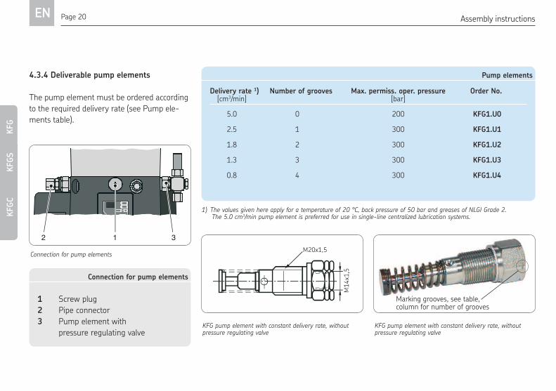
Pump elements
Delivery rate 1) Number of grooves Max. permiss. oper. pressure Order No. [cm3/min] [bar]
5.0 0 200 KFG1.U0
2.5 1 300 KFG1.U1
1.8 2 300 KFG1.U2
1.3 3 300 KFG1.U3
0.8 4 300 KFG1.U4
1) The values given here apply for a temperature of 20 °C, back pressure of 50 bar and greases of NLGI Grade 2. The 5.0 cm3/min pump element is preferred for use in single-line centralized lubrication systems.
M20x1,5
M1
4x1,5
KFG pump element with constant delivery rate, without pressure regulating valve
KFG pump element with constant delivery rate, without pressure regulating valve
4.3.4 Deliverable pump elements
The pump element must be ordered according
to the required delivery rate (see Pump ele-
ments table).
2 1 3
Connection for pump elements
1 Screw plug
2 Pipe connector
3 Pump element with
pressure regulating valve
Connection for pump elements
Marking grooves, see table, column for number of grooves
Assembly instructions

Page 21 EN
KFG
SK
FG
KFG
CK
FG
SK
FG
KFG
C
4.3.5 Pressure regulating valve
A pressure regulating valve (1) protects the
entire lubrication system against excessive sy-
stem pressure. It is mounted directly on the
pump element (2). The cracking pressure set
for this valve is 300 bar or 200 bar, depending
on the valve design. If a blocked feeder or a lu-
brication point causes operating pressure to
rise above 300 (200) bar, the valve opens, fol-
lowed by a noticeable discharge of grease (3).
This also serves as a form of visual system
monitoring.
This protects the pump unit against damage.
A further option are pressure regulating valves
with an emergency lubricant nipple. These can
be used with manual grease presses to provide
the lubrication system with adequate lubricant
in case of power failure or a defective pump.
P
A
P
M14x1,5
R
R
A
Connections for pressure regulating valves
A Connection for pipe ØP Pipe thread for pump elementR Grease discharge at overpressure
NoteThe pressure regulating valve is available with an optional lubricant nipple.
pressure regulating valve
2
1
3
Connection for pressure regulating valve
Spare parts
Pressure regulating valve without lubricant nipple
Pipe Ø Cracking pressure Order number [mm] [bar]
6 300 161-210-012
6 200 161-210-032
8 300 161-210-018
8 200 161-210-031
10 300 161-210-016
10 200 161-210-030
Pressure regulating valve with lubricant nipple
6 300 161-210-014
8 300 161-210-025
Pressure regulating valve with pressure gauge
6 300 161-210-046
8 300 161-210-047
10 300 161-210-048
Assembly instructions

Page 22 ENK
FG
SK
FG
KFG
CAssembly instructions
4.4 Instructions on lubricant illingOnlyillusingcleanlubricantandanappropriateillingdevice.Contaminatedlubricants can result in severe system
malfunction.
Thelubricantreservoirisilledindifferentways based on the design.
4.4.1 Lubricant illingLubricantillingisperformedusinga DIN 71412-AM10x1 conical head nipple (1)
and a conventional grease press.
The conical head nipple can be twisted onto
the position (2), for example to gain better
access. As an alternative, the connection (2)
can be used to mount a lubricant return or
illercoupling(seefollowingpage).
2 1
Filler sockets/lubricant return
R
AP
R
M1
4x
1,5
P A
Pressure regulating valve with T connector
Connections for pressure regulating valve
with T connector
A Connection for pipe ØP Pipe thread for pump elementR Grease discharge at overpressure
Cracking pressure........ 300 ± 20 barNominal pipe sizes Ø .. 6, 8, 10 mm
pressure regulating valve
Pressure regulating valve with T connector output
Pipe Ø Cracking pressure Order number [mm] [bar]
6 300 161-210-038
6 200 161-210-032
8 300 161-210-039
8 200 161-210-031
10 300 161-210-016
10 200 161-210-030

Page 23 EN
KFG
SK
FG
KFG
C
Assembly instructions
4.4.2 Filler coupling
As an alternative or addition to a conical head
nipple (1), the unit can also be equipped with a
illersocket(partNo.995-000-705)(2)toillusingaillingpump.Acorrespondingcouplingsocket (part No. 995-001-500) (3) must be
mountedontheillingpump.Thecapontheillersocketmustberemovedbeforeilling.
Filling via filler coupling
4.4.3 Filling cylinder
Thepumpunitcanalsobeilledthroughoneofthelubricantoutletsusingaillingcylinder(1). To do this, remove the M20x1.5 screw plug
(2) in the lubricant outlet and replace it with a
illersocket(partNo.169-000-174)(3). The
caps (4)onthesocketandillingcylindermustberemovedbeforeilling.
4.4.4 Filling cover
Aspecialdesignforthepumpunitsisilledwith lubricant through a special hinged lid or a
screw cap.
Filling via filling cylinder
Onlyillusingcleanlubricantandanappropriateillingdevice.Notsuitableincase of highly contaminated pumps and
surrounding areas.
Filling cover versions
995-000-705
995-001-500
KFG3-5; KFGS3-5 KFG5-5; KFGS5-5
KFG1-5W2; KFGS1-5W2(for NLGI Grade 1 greases)
KFGS1-5
Filler socket 169-000-174
Filling cylinder169-000-171

Page 24 EN
24 V GLEICHSTROM
Made in Germany
KFG ....
Grease/Fett NLGI-2
4.5 Electrical connection
Warning!
Compare the operating voltage with the
speciicationsontheratingplate.
4.5.1 General conditions for electrical connections
KFG; KFGS; KFGC, general conditions for electrical connections
Nominal Power Power Pump Max. voltage consumption consumption starting current pre-connected fuse (load-dependent) (max.) (approx. 20 ms)
24 VDC 1) 1.25 A 2) < 2.5 A 4.5 A 4 A 3) 4)
12 VDC 1) 2.4 A 2) < 5 A 9 A 6 A 3) 4)
115 VAC N/A5) 1.5 A 20 A C6A
230 VAC N/A5) 0.9 A 40 A C6A
KFGC (CAN bus)
Switching outputs: Type: Solid-state output, short-circuit-proof and overload-proof Max. current-carrying capacity: - with simultaneous operation of 4 outputs 1.0 A - with simultaneous operation of 2 outputs 1.25 A - with operation of 1 output 1.5 AModes of operation: - Single operation - Parallel connection of multiple outputs while simultaneously increasing output current Signal inputs: Type: digital solid-state input, short-circuit-proofConnectivity: - Switching contact, no detection of wire breakage - Dual wire sensors (e.g., piston detector), detection of wire breakage
1) Protective measures that must be applied for designated usage: "Functional Extra Low Voltage," "Protective Extra Low Voltage“ (PELV) Standards: EN 60204 Part 1: IEC 60204-1: DIN VDE 0100 Part 410 / IEC 364-4-41: HD384.4.41
2) Typical value at ambient temperature = 25°C and operating pressure = 150 bar3) Fuse per DIN 72581 T.34) Conductor: cross-section 1.5 mm2, length ≤ 12 m5) No specification
Operating voltage
Operating voltage specification on rating plate
KFG
SK
FG
KFG
CAssembly instructions

Page 25 EN
4.5.2 KFG series
The KFG pump unit is available in the voltage
designs 12 VDC or 24 VDC and in 90-264 VAC
and 120-370 VDC designs.
The electrical voltage connection is established
through a 4-pin cable socket according to
DIN EN 175301-803.
Depending on the pump unit design, an addi-
tionalplugforilllevelcontroland/oraplugfora pump-side pressure relief valve (single-line
centralized lubrication system) can be inte-
grated into the pump housing.
The standard connections are presented below
(special designs may differ).
4.5.2.1 Power supply 12/24 VDC
2
3 1
L+
1
KFG...DC
2 3X1
+
M-
L-
4.5.2.2 Power supply 90-264 VAC
2
3 1
KFG...AC
X1 1 2 3
M
DC
AC
1)
C6AF
L1 N PE
90 - 264 V AC47 - 440 Hz
Connector pin assignment for 90-264 VAC
PIN Description
1 L1 Main machine switch ON 2 N 3 Plug not assigned PE Protective earth
Connector pin assignment for 12/24 VDC
PIN Description
1 (Current) = L + Supply voltage potential (Main machine switch ON) 2 (Ground) = M - Supply voltage potential (0 V, GND)
Cable socket per DIN EN 175301-803
Cable socket per DIN EN 175301-803
1) = External control device "relay contact" "pump on"
4 AT
KFG
Assembly instructions

Page 26 EN
4.5.2.4 Fill level monitoring
4.5.2.3 External control
Type: W1 (max. 24 VDC)
for NLGI Grade 2 greases
Note
The external control units listed in
Chapter 17 are designed to control the
lubrication and interval times, as well as
to monitor the lubrication process.
Technical data
Fill level monitoring Function . . . . . . mechanical, via floating reed contactForm of contact . . . . . NO-contactSwitching capacity, . . max.0.6 WSwitching voltage, . . . max. 24 VDCSwitched current,. . . . max. 25 mA;
only ohm load 1)Plug-in connection . .DIN EN 60947/IEC 947 2)Connection diagram .M12x1 circular connectors
1) No inductive load, no lamp load (signal lamp)
2) Cable socket - see Accessories, Chapter 17
W1 connector pin assignment (pump unit)
PIN Description
1 = Supply voltage 2 = Signal output (W1) 3 = Not assigned 4 = Not assigned
Socket connection per
EN 60947/IEC 947
3 4
12
Functional description
The W1 fill level switch is designed as a rocker
switch and is integrated in the bottom of the
reservoir. A magnetic rocker mounted on the
agitator is turned downward by the grease re-
sistance when the reservoir is full. A pulse is
generated at each revolution of the agitator.
When the minimum fill level is reached, the
resistance the grease exerts on the rocker
subsides. The rocker turns back and the pulses
are interrupted.
Contact W1 open, fault position
Contact W1 closed, go position
KFG
Assembly instructions
1 2 3 4
+ Sig
Page 27 EN
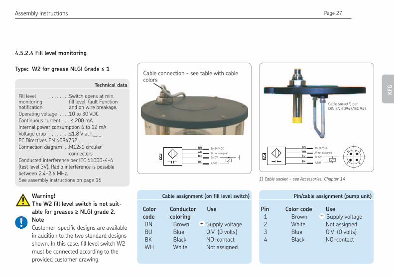
Cable connection - see table with cable colors
BN
WH
BU
BK
1/+24 V DC
2/ not assigned
3/-OV
4/NO
4.5.2.4 Fill level monitoring
Technical data
Fill level . . . . . . . .Switch opens at min.monitoring fill level, fault Function notification and on wire breakage.Operating voltage . . . .10 to 30 VDCContinuous current . . .≤200mAInternal power consumption 6 to 12 mAVoltage drop . . . . . . . .≤1.8VatI
duration
EC Directives EN 6094752Connection diagram . . M12x1 circular
connectorsConducted interference per IEC 61000-4-6(test level 3V). Radio interference is possible between 2.4-2.6 MHz. See assembly instructions on page 16
Warning!
The W2 ill level switch is not suit-able for greases ≥ NLGI grade 2. Note
Customer-speciicdesignsareavailablein addition to the two standard designs
shown.Inthiscase,illlevelswitchW2must be connected according to the
provided customer drawing.
Cable assignment (on fill level switch)
Color Conductor Use
code coloring
BN Brown Supply voltage BU Blue O V (0 volts) BK Black NO-contact WH White Not assigned
Pin/cable assignment (pump unit)
Pin Color code Use 1 Brown Supply voltage 2 White Not assigned 3 Blue O V (0 volts) 4 Black NO-contact
Cable socket 1) per DIN EN 60947/IEC 947
1) Cable socket - see Accessories, Chapter 14
KFG
Assembly instructions
Type: W2 for grease NLGI Grade ≤ 1
BN
WH
BU
BK
1/+24 V DC
2/ not assigned
3/-OV
4/NO
12
43
Page 28 EN
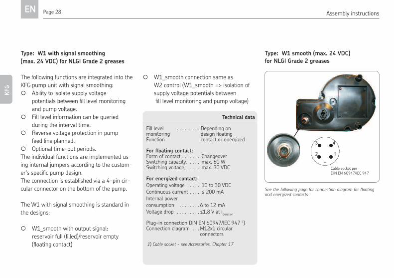
Type: W1 with signal smoothing
(max. 24 VDC) for NLGI Grade 2 greases
Type: W1 smooth (max. 24 VDC)
for NLGI Grade 2 greases
Technical data
Fill level . . . . . . . . . Depending onmonitoring design floatingFunction contact or energized
For floating contact:Form of contact . . . . . . . ChangeoverSwitching capacity, . . . . max. 60 WSwitching voltage, . . . . . max. 30 VDC
For energized contact:Operating voltage . . . . . 10 to 30 VDCContinuous current . . . . ≤200mAInternal power consumption . . . . . . . . 6 to 12 mAVoltage drop . . . . . . . . . ≤1.8VatI
duration
Plug-in connection DIN EN 60947/IEC 947 1)Connection diagram . . . M12x1 circular
connectors 1) Cable socket - see Accessories, Chapter 17
Cable socket per DIN EN 60947/IEC 947
See the following page for connection diagram for floating and energized contacts
W1_smooth connection same as
W2 control (W1_smooth => isolation of
supply voltage potentials between
illlevelmonitoringandpumpvoltage)
The following functions are integrated into the
KFG pump unit with signal smoothing:
Ability to isolate supply voltage
potentialsbetweenilllevelmonitoring and pump voltage.
Fill level information can be queried
during the interval time.
Reverse voltage protection in pump
feed line planned.
Optional time-out periods.
The individual functions are implemented us-
ing internal jumpers according to the custom-
er'sspeciicpumpdesign.The connection is established via a 4-pin cir-
cular connector on the bottom of the pump.
The W1 with signal smoothing is standard in
the designs:
W1_smooth with output signal:
reservoirfull(illed)/reservoirempty (loatingcontact)
KFG
Assembly instructions
Page 29 EN
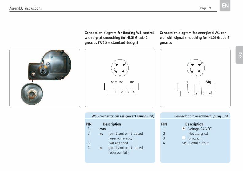
Connector pin assignment (pump unit)
PIN Description
1 Voltage 24 VDC 2 Not assigned
3 Ground 4 Sig Signal output
Connection diagram for energized W1 con-
trol with signal smoothing for NLGI Grade 2
greases
Connection diagram for loating W1 control with signal smoothing for NLGI Grade 2
greases (W1G = standard design)
W1G connector pin assignment (pump unit)
PIN Description
1 com
2 nc (pin 1 and pin 2 closed, reservoir empty) 3 Not assigned 4 nc (pin 1 and pin 4 closed, reservoir full)
KFG
Assembly instructions
1 2 3 4
+ - Sig
1 2 3 4
com nc no

Page 30 EN
4.5.2.5 Pressure relief valve with integrated
pressure regulating valve
(for single-line systems with VR distributors)
Technical data
Pressure relief valve 24 VDC
Input voltage . . . . . . . . . . . . . 24 VDC Rated output . . . . . . . . . . . . . 26 W Rated current . . . . . . . . . . . . 1.2 A ON-time . . . . . . . . . . . . . . . . 100%Protection class . . . . . . . . . . . IP 65pressure regulating valveSet pressure . . . . . . . . . . . . .200 bar
Plug-in connection per DIN EN 175301803
Pressure relief valve 230 VAC Input voltage . . . . . . . . . . . . . 230 VACCoil voltage . . . . . . . . . . . . . . . 205 VDCRated output . . . . . . . . . . . . . 26 WRated current . . . . . . . . . . . . 0.13 AON-time . . . . . . . . . . . . . . . . 100% at 35 °C
pressure regulating valveSet pressure . . . . . . . . . . . . .200 bar
Protection class . . . . . . . . . . . IP 65Plug-in connection per DIN EN 17530-803
Plug-in connection per DIN EN 17530-803
20
0bar
P2
A
TP1
Hydraulic block diagram
Electrical block diagram
Connector pin assignment
PIN Description
1 (Current) Supply voltage potential
2 Ground 3 PE
Note
When VKR distributors are used, a max. set
pressure of 130 bar for the pressure regulating
valve must not be exceeded.
KFG
Assembly instructions
Page 31 EN
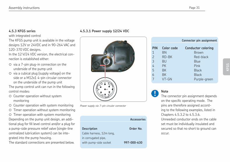
4.5.3.1 Power supply 12/24 VDC4.5.3 KFGS series
with integrated control
The KFGS pump unit is available in the voltage
designs 12V or 24VDC and in 90-264 VAC and
120-370 VDC designs.
In the 12 V/24 VDC version, the electrical con-
nection is established either:
via a 7-pin plug-in connection on the underside of the pump unit
via a cubical plug (supply voltage) on the side or a M12x1 4-pin circular connector on the underside of the pump unit
The pump control unit can run in the following
control modes:
Counter operation without system
monitoring
Counter operation with system monitoring
Timer operation without system monitoring
Timer operation with system monitoring
Depending on the pump unit design, an addi-
tionalplugforilllevelcontroland/oraplugfora pump-side pressure relief valve (single-line
centralized lubrication system) can be inte-
grated into the pump housing.
The standard connections are presented below.
2
4
5
3
1
67
Connector pin assignment
PIN Color code Conductor coloring
1 BN Brown2 RD-BK Red-black3 BU Blue4 PK Pink5 BK Black6 BK Black7 VT-GN Purple-green
Power supply via 7-pin circular connector
Note
The connector pin assignment depends
onthespeciicoperatingmode.Thepins are therefore assigned accord-
ing to the following examples, listed in
Chapters 4.5.3.2 to 4.5.3.6.
Unneeded conductor ends on the cable
set must be individually insulated and
secured so that no short to ground can
occur.
Accessories
Description Order No.
Cable harness, 12m long,
in corrugated pipe,
with pump-side socket 997-000-630
KFG
S
Assembly instructions

Page 32 EN
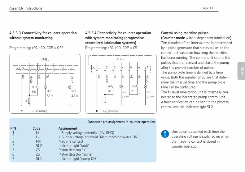
4.5.3.2 Connectivity for counter operation
without system monitoring
1
BN
KFGS...
F
2 3 4 5 6 7X1
RD
-BK
BU
M L+ (Please consider the starting current !)
MK-machine contact
The interval depends on the number of pulses.
The pump cycle time is time-dependent.
Connector pin assignment
PIN Code Assignment
1 M - Supply voltage potential (0 V, GND) 2 L+ + Supply voltage potential 3 L+/MK + Machine contact potential
Programming:
cPA, tCO, COP = OFF - see Chapter 6
Accessories
Description Order No.Cable harness, in corrugated pipe, with pump-side socket 8 m length 997-000-76013.12 yd length 997-000-63017.50 yd length 997-000-650
Settings for progressive lubrication
KFG
SAssembly instructions
Page 33 EN
M L+ (Industrie)
1
BN
KFGS...
F
2 3 4 5 6 7X1
RD
-BK
BU
PK
VT-
GN
MK SL2
2,4 W
SL1
2,4 W
4.5.3.3 Connectivity for counter operation
without system monitoring
Connector pin assignment in counter operation
PIN Code Assignment 1 M - Supply voltage potential (0 V, GND) 2 L+ + Supply voltage potential "Main machine switch ON" 3 MK Machine contact 4 SL2 Indicator light "fault" 5 ZS Piston detector "+" 6 ZS Piston detector "signal" 7 SL1 Indicator light "pump ON"
4.5.3.4 Connectivity for counter operation
with system monitoring (progressive
centralized lubrication systems)
Programming: cPA, tCO, COP = OFF
M L+ (Industrie)
1
BN
KFGS...
F
2 3 4 5 6 7X1
RD
-BK
BU
PK
VT-
GN
MK SL2
2,4 W
SL1
2,4 W
BK
BK
ZS+
Programming: cPA, tCO, COP = CS
One pulse is counted each time the
operating voltage is switched on when
the machine contact is closed in
counter operation.
Control using machine pulses
(Counter mode = load-dependent lubrication)
The duration of the interval time is determined
by a pulse generator that sends pulses to the
control unit based on how long the machine
has been running. The control unit counts the
pulses that are received and starts the pump
after the pre-set number of pulses.
Thepumpcycletimeisdeinedbyatimevalue. Both the number of pulses that deter-
mine the interval time and the pump cycle
timecanbeconigured.Theilllevelmonitoringunitisinternallycon-
nected to the integrated pump control unit.
Afaultnotiicationcanbesenttotheprocesscontrol level via indicator light SL2.
KFG
S
Assembly instructions

Page 34 EN
4.5.3.5 Connectivity for timer operation
without system monitoring
Connector pin assignment in timer operation
PIN Code Assignment
1 M - Supply voltage potential (0 V, GND) 2 L+ + Supply voltage potential "Main machine switch ON"3 DK Pushbutton"1stInterimlubrication""2ndDeletefaultnotiication" 4 SL2 Indicator light "fault" 5 PS Pressure switch " + " 6 PS Pressure switch "signal" 7 SL1 Indicator light "pump ON"
4.5.3.6 Connectivity for timer operation
with system monitoring
(single-line centralized lubrication system)
Programming: tPA, tCO, COP = OFF
1
BN
KFGS...
F
2 3 4 5 6 7X1
RD
-BK
BU
PK
VT-
GN
DK SL2
2,4 W
M L+ (Industrie)
SL1
2,4 W
1
BN
KFGS...
F
2 3 4 5 6 7X1
RD
-BK
BU
PK
VT-
GN
DK SL2
2,4 W
SL1
2,4 W
BK
BK
PS+
M L+ (Industrie)
Programming: tPA, tCO, COP = PS
Timer mode
In timer mode, the interval time is determined
byatimevalue.Itisconiguredbyenteringatime value in hours.
Thepumpcycletimeisconiguredusingatimevalue in minutes.
Theilllevelmonitoringunit(W1control)isinternally connected to the integrated pump
controlunit.Afaultnotiicationcanbesenttothe process control level via indicator light SL2.
Settings for single-line lubrication
KFG
SAssembly instructions

Page 35 EN
The "Timer operation with system
monitoringandilllevelcontrol"con-
nectivity option (Chapter 6.5.5.1) is
also available in an advanced version
with a piston detector and fault signal.
A T connector with a special cable
adapter is required for this.
Youcanindthis,alongwithanillus-
tration of the connection, under
Accessories, Chapter 17.
4.5.3.7 Power supply 12/24 VDC
using a cubical plug
Connector pin assignment per
DIN EN 175 301-803
Youcanindtechnicaldataandtheorder number of the M12x1
circular connector (mating part for
circular plug socket) required by the
customer in brochure No. 1-1730,
"Electric Plug-and-Socket Connectors."
KFGS connections for progressive and single-line systems
L+
1
KFG...DC
2 3X1
+
M-
L-
Connector pin assignment for 12/24 VDC
PIN Description
1 (Current) = L + Supply voltage potential (Main machine switch ON) 2 - (Ground) = M - Supply voltage potential (0 V, GND)
KFG
S
Assembly instructions
2
3 1

Page 36 EN
Socket pin assignment
PIN Color code Conductor coloring
1 BN Brown 2 WH White 3 BU Blue 4 BK Black
3 4
12
M12x1 circular plug socket per EN60947-5-2
4.5.3.8 12/24 VDC connections for
system monitoring using an
M12x1 circular plug socket
4.5.3.9 Connectivity for timer operation
without system monitoring
(and ill level control)Programming: tPA, tCO, COP = OFF
24 VDC +
X2 1 2 3
SL2
4
BU
BK
SL22,4W
Connector pin assignment in timer operation
PIN Code Assignment
3 SL2 "Fault" indicator light ( - ) 4 SL2 "Fault" indicator light ( + )
4.5.3.10 Connectivity for timer operation
with system monitoring
(and ill level control)Programming: tPA, tCO, COP = CS or PS
24 VDC +
X2
1 2 3
SL2
4
BN
WH
BU
BK
BN
BU
BK
X5
CS/PSSL22,4W
1 2 3
Connector pin assignment in timer operation
PIN Code Assignment
1 Voltage ( + ) 2 CS/PS Cycle/pressure switch (signal) 3 SL2 "Fault" indicator light ( - ) 4 SL2 "Fault" indicator light ( + )
KFG
SAssembly instructions

Page 37 EN
4.5.4.1 Pressure relief valve with integrated
pressure regulating valve
(for single-line systems with VR distributors)
Plug-in connection per DIN EN 17530-803
20
0bar
P2
A
TP1
Hydraulic block diagram
Electrical block diagram
Connector pin assignment
PIN Description
1 (Current) Supply voltage potential 2 Ground 3 PE
Technical data
Pressure relief valve 24 VDC
Input voltage . . . . . . . . . . . . . 24 VDC Rated output . . . . . . . . . . . . . 26 W Rated current . . . . . . . . . . . . 1.2 A ON-time . . . . . . . . . . . . . . . . 100%Protection class . . . . . . . . . . . IP65
pressure regulating valveSet pressure . . . . . . . . . . . . .200 bar
Plug-in connection per DIN EN 175301803
Pressure relief valve 230 VAC Input voltage . . . . . . . . . . . . . 230 VACCoil voltage . . . . . . . . . . . . . . . 205 VDCRated output . . . . . . . . . . . . . 26 WRated current . . . . . . . . . . . . 0.13 AON-time . . . . . . . . . . . . . . . . 100% at 35 °C
pressure regulating valveSet pressure . . . . . . . . . . . . .200 bar
Protection class . . . . . . . . . . . IP65
Plug-in connection per DIN EN 17530-803
Note
When VKR distributors are used, a
max. set pressure of 130 bar for the pressure
regulating valve must not be exceeded.
KFG
S
Assembly instructions
Page 38 EN
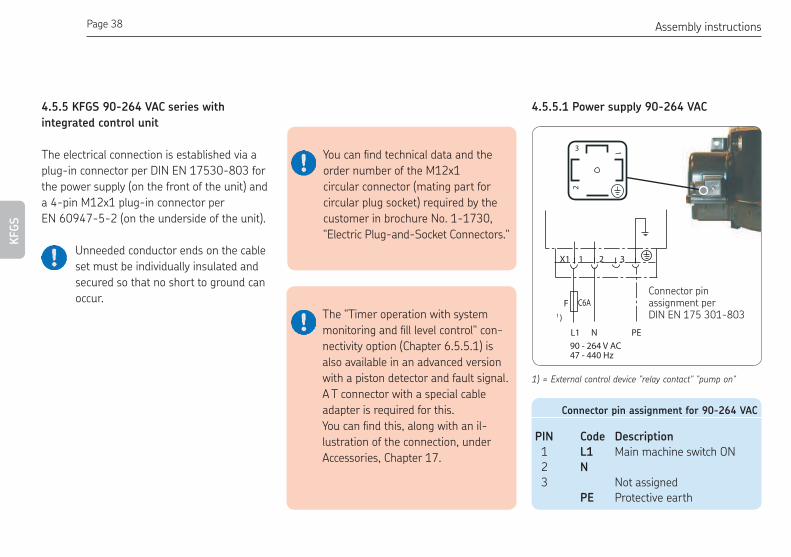
4.5.5 KFGS 90-264 VAC series with
integrated control unit
The electrical connection is established via a
plug-in connector per DIN EN 17530-803 for
the power supply (on the front of the unit) and
a 4-pin M12x1 plug-in connector per
EN 60947-5-2 (on the underside of the unit).
Unneeded conductor ends on the cable
set must be individually insulated and
secured so that no short to ground can
occur.
4.5.5.1 Power supply 90-264 VAC
X1 1 2 3
L1 N PE
90 - 264 V AC47 - 440 Hz
C6AF
)1
Connector pin assignment for 90-264 VAC
PIN Code Description
1 L1 Main machine switch ON 2 N
3 Not assigned PE Protective earth
1) = External control device "relay contact" "pump on"
Connector pin assignment per DIN EN 175 301-803The "Timer operation with system
monitoringandilllevelcontrol"con-
nectivity option (Chapter 6.5.5.1) is
also available in an advanced version
with a piston detector and fault signal.
A T connector with a special cable
adapter is required for this.
Youcanindthis,alongwithanil-lustration of the connection, under
Accessories, Chapter 17.
Youcanindtechnicaldataandtheorder number of the M12x1
circular connector (mating part for
circular plug socket) required by the
customer in brochure No. 1-1730,
"Electric Plug-and-Socket Connectors."
KFG
SAssembly instructions
2
3 1
Page 39 EN
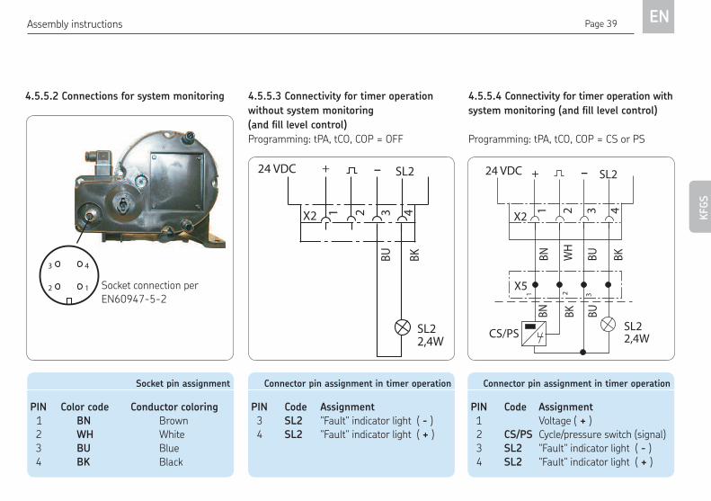
4.5.5.3 Connectivity for timer operation
without system monitoring
(and ill level control)Programming: tPA, tCO, COP = OFF
24 VDC +
X2 1 2 3
SL2
4
BU
BK
SL22,4W
4.5.5.4 Connectivity for timer operation with
system monitoring (and ill level control)Programming: tPA, tCO, COP = CS or PS
Socket pin assignment
PIN Color code Conductor coloring
1 BN Brown 2 WH White 3 BU Blue 4 BK Black
3 4
12 Socket connection per EN60947-5-2
4.5.5.2 Connections for system monitoring
Connector pin assignment in timer operation
PIN Code Assignment
3 SL2 "Fault" indicator light ( - ) 4 SL2 "Fault" indicator light ( + )
Connector pin assignment in timer operation
PIN Code Assignment
1 Voltage ( + ) 2 CS/PS Cycle/pressure switch (signal) 3 SL2 "Fault" indicator light ( - ) 4 SL2 "Fault" indicator light ( + )
24 VDC +
X2
1 2 3
SL2
4
BN
WH
BU
BK
BN
BU
BK
X5
CS/PSSL22,4W
1 2 3
KFG
S
Assembly instructions
Page 40 EN
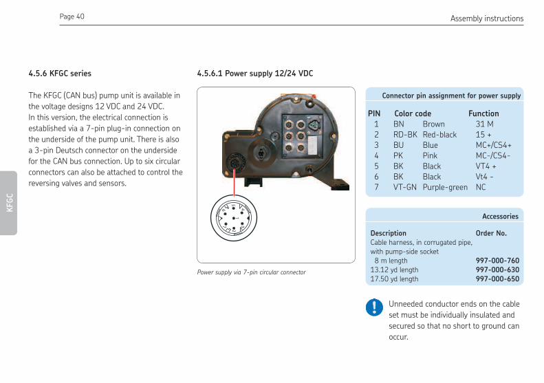
4.5.6 KFGC series
The KFGC (CAN bus) pump unit is available in
the voltage designs 12 VDC and 24 VDC.
In this version, the electrical connection is
established via a 7-pin plug-in connection on
the underside of the pump unit. There is also
a 3-pin Deutsch connector on the underside
for the CAN bus connection. Up to six circular
connectors can also be attached to control the
reversing valves and sensors.
4.5.6.1 Power supply 12/24 VDC
2
4
5
3
1
67
Connector pin assignment for power supply
PIN Color code Function
1 BN Brown 31 M 2 RD-BK Red-black 15 + 3 BU Blue MC+/CS4+ 4 PK Pink MC-/CS4- 5 BK Black VT4 + 6 BK Black Vt4 - 7 VT-GN Purple-green NC
Power supply via 7-pin circular connector
Unneeded conductor ends on the cable
set must be individually insulated and
secured so that no short to ground can
occur.
Accessories
Description Order No.Cable harness, in corrugated pipe, with pump-side socket 8 m length 997-000-76013.12 yd length 997-000-63017.50 yd length 997-000-650
Assembly instructionsK
FG
C
Page 41 EN
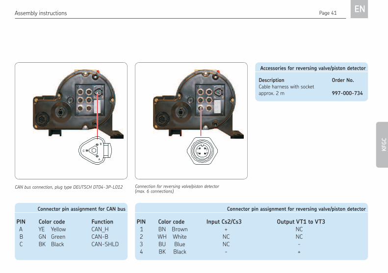
Connector pin assignment for CAN bus
PIN Color code Function
A YE Yellow CAN_H B GN Green CAN-B C BK Black CAN-SHLD
CAN bus connection, plug type DEUTSCH DT04-3P-L012
A
B
C
Connection for reversing valve/piston detector (max. 6 connections)
Accessories for reversing valve/piston detector
Description Order No.Cable harness with socketapprox. 2 m 997-000-734
34
1 2
Connector pin assignment for reversing valve/piston detector
PIN Color code Input Cs2/Cs3 Output VT1 to VT3
1 BN Brown + NC 2 WH White NC NC 3 BU Blue NC - 4 BK Black - +
Assembly instructions
KFG
C

Page 42 EN
V3V2V1
111111 222222 333333 444444
1 2 3 4 1 2 2 12 1 2 11 2 3 4 1 2 3 4 1 2 3 4
A B C1 2 3 4 5 6 7X1
BN
RD
-BK BU
PK
BK
BK
VT-
GN CAN-BUS
M1
2x
1
1x
21
M1
x2
1M
M1
2x
11x
21
M1
x2
1M
M1
2x
11x
21
M1
x2
1M
M1
2x
1
F1
S1
M L+
31 30
15
CS4 (MC) V4
SL2
RD CS1
CS1
CS2
CS2
CS3
CS3
V1 V2 V3
+++++++ + + –– – – –
4.5.6.2 Connectivity
Example of connecting four reversing valves
and four piston detectors on devices with the
maximum equipment level (6x M12x1 circular
connectors) for operating a progressive feeder
system, distributed in four lubrication zones
A
B
C
CS.. = Piston detectors V.. = Reversing valves
2
4
5
3
1
67
34
1 2
Assignment of round 7-pin plug
Assignment of M12x1 4-pin round plug
Customer-speciicdeviations are possible.
Legend for connection illustration with maximum equipment level
CS1 – CS4 Piston detectors 1 – 4 V1 – V4 Valves 1 – 4MC Machine contact SL2 "Fault" indicator light can alternately be operated in place of valve 4)L+ + Supply voltage potential S1 Ignition switch F1 Fuse
Assignment of CAN bus plug
KFG
CAssembly instructions
Page 43 EN
1 2 3 4 1 2
A B C1 2 3 4 5 6 7X1
BN
RD
-BK BU
PK
BK
BK
VT-
GN CAN-BUS
M1
2x1
F1
S1
M L+
31 30
15
CS4 (MC) V4
SL2
RD
KFGS...-...B...+ + + ––
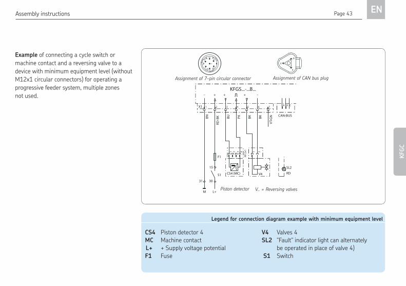
Example of connecting a cycle switch or
machine contact and a reversing valve to a
device with minimum equipment level (without
M12x1 circular connectors) for operating a
progressive feeder system, multiple zones
not used.
Piston detector
Assignment of 7-pin circular connector
2
4
5
3
1
67
A
B
C
Legend for connection diagram example with minimum equipment level
CS4 Piston detector 4 V4 Valves 4MC Machine contact SL2 "Fault" indicator light can alternately L+ + Supply voltage potential be operated in place of valve 4)F1 Fuse S1 Switch
Assignment of CAN bus plug
V.. = Reversing valves
KFG
C
Assembly instructions
Page 44 ENK
FG
C
4.5.6.4 CAN bus system coniguration with connection to CAN bus system
ThesesystemsareconiguredviatheCANbusconnection. Please see the "LC-CAN 5000
ConigurationandControlInterfaceProtocol"manualfordetailsonconiguringandcom-
municating with the control unit over the CAN
network using the SAE J1939 communication
protocol.
4.5.6.5 CAN bus system coniguration without connection to CAN bus system
Systems without a connection to a CAN bus
systemareconiguredusingaPCwithanIrDAinterface.
Aconigurationprogramneedstobeinstalledon the PC to do this. You can obtain this pro-
gram from the SKF Service Center.
DisplayCAN Bus
24 VDC
M
M
1
23
4 5 6 7
CS1CS2
CS3CS4
1 2
3
5
4
Connector 3
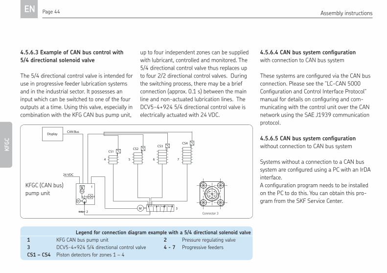
4.5.6.3 Example of CAN bus control with
5/4 directional solenoid valve
The 5/4 directional control valve is intended for
use in progressive feeder lubrication systems
and in the industrial sector. It possesses an
input which can be switched to one of the four
outputs at a time. Using this valve, especially in
combination with the KFG CAN bus pump unit,
up to four independent zones can be supplied
with lubricant, controlled and monitored. The
5/4 directional control valve thus replaces up
to four 2/2 directional control valves. During
the switching process, there may be a brief
connection (approx. 0.1 s) between the main
line and non-actuated lubrication lines. The
DCV5-4+924 5/4 directional control valve is
electrically actuated with 24 VDC.
Legend for connection diagram example with a 5/4 directional solenoid valve
1 KFG CAN bus pump unit 2 Pressure regulating valve
3 DCV5-4+924 5/4 directional control valve 4 - 7 Progressive feeders
CS1 – CS4 Piston detectors for zones 1 – 4
KFGC (CAN bus)
pump unit
Assembly instructions

Page 45 EN
KFG
SK
FG
KFG
C
4.7 Progressive system ventilation4.6 Fill level control for pump unit
Visual
The transparent lubricant reservoir allows for
visualilllevelcontrol.Thismustbeperformedon a regular basis for safety reasons.
The entire system must be ventilated if
the reservoir has been emptied below
the "min" mark.
Automatic
Pumps of the KFGS series allow for automatic
illlevelcontrol.Iftheilllevelfallsbelowthe"min" mark, the lubrication process is stopped
andthefaultnotiication"FLL"isissuedonthedisplay.
Fill pump with lubricant.
Remove main lines on unit.
Allow pump to run until lubricant without
bubbles is discharged at the straight con-
nector on the pump element.
Mount main lines.
Allow pump to run until grease can be seen
discharging at all lubrication points.
4.8 Single-line system ventilation
Fill pump with lubricant.
Remove main lines (pressure relief valve as
necessary) on unit.
Allow pump to run until lubricant without
bubbles is discharged at the straight con-
nector.
Mount main lines.
Remove screw plug or pressure switch at
end of main and branch lines.
Allow pump to run until air is no longer
discharged at the end of the spool pieces.
Mount screw plug or pressure switch.
Vent lubrication lines and lubrication points
and inspect for proper function.
Assembly instructions

Page 46 EN
24 V DC
Made in Germany
KFG ....
Grease/Fett NLGI-2
4.9 Note on the rating plate
Rating plates on KFG and KFGS pump units
provide important key data such as designa-
tion and material description (or customer
number).
To avoid loss of this data in case the rating
plate becomes illegible, these characteristics
should be entered in the following table.
Enter key data from rating plate in the
following table.
Type designation
Barcode
Power supply
Serial number
Page 47 EN
Original operating instructionsacc. to 98/37/EC, Annex II B
for partly completed machinery
Operating instructions associated with assembly instructions according to EC Dir. 2006/42/EC for partly completed machinery
KFG; KFGS; KFGC (CAN bus) for industrial use
Page 48 EN 1. Safety instructions / 2. Lubricants
1. Safety instructions
Warning!
These operating instructions must be
read and properly understood by the
assembler and the responsible techni-
cal personnel/operator before assembly
and commissioning.
The safety instructions listed in Chapter 1,
"Safety instructions," of the assembly instruc-
tions also apply without restrictions to these
operating instructions.
General
In addition to the operating instructions,
general statutory regulations and other
binding regulations for accident preven-
tion and for environmental protection
(recycling/disposal) must be observed
and applied.
2. Lubricants
Warning!
The information on lubricants listed in
Chapter 2, "Lubricants," of the assembly
instructions also applies without restric-
tions to these operating instructions.
Disclaimer of liability
SKF Lubrication Systems Germany GmbH shall not be held liable for damages:
Caused by contaminated or unsuitable
lubricants
Caused by the installation of non-original
SKF components or SKF spare parts
Caused by inappropriate usage
Resultingfromimproperassembly,conigu-
rationorilling Resulting from improper response to mal-
functions
Causedbyindependentmodiicationofsystem components
Only media approved for these types of
pump units may be used. Unsuitable
media may result in pump unit failure and
potentially severe bodily injury and property
damage.
KFG
SK
FG
KFG
C
Page 49 EN
3. Transport, delivery, and storage
3. Transport, delivery, and storage
KFG
SK
FG
KFG
C
Warning!
The product must not be tilted or
dropped.
SKF Lubrication Systems Germany GmbH
products are packaged in accordance with
standard commercial practice according to the
regulations of the recipient's country and DIN
ISO 9001. During transport, safe handling
must be ensured and the product must be
protected from mechanical effects such as im-
pacts. The transport packaging must be
marked "Do not drop!"
There are no restrictions for land, air or sea
transport.
After receipt of the shipment, the product(s)
must be inspected for damage and for com-
pleteness according to the shipping docu-
ments. The packaging material must be pre-
served until any discrepancies are resolved.
SKF Lubrication Systems Germany GmbH
products are subject to the following storage
conditions:
3.1 Lubrication units
Ambient conditions: dry and dust-free
surroundings, storage in well ventilated
dry area
Storage time: max. 24 months
Permissible humidity: < 65%
Storage temperature: 10 - 40°C
Light: avoid direct sun or UV exposure and
shield nearby sources of heat
3.2 Electronic and electrical devices
Ambient conditions: dry and dust-free
surroundings, storage in well ventilated
dry area
Storage time: max. 24 months
Permissible humidity: < 65%
Storage temperature: 10 - 40°C
Light: avoid direct sun or UV exposure and
shield nearby sources of heat
3.3 General notes
The product(s) can be enveloped in plastic
film to provide low-dust storage.
Protect against ground moisture by
storing on a shelf or wooden pallet.
Bright-finished metallic surfaces, espe-
cially wearing parts and assembly surfac-
es, must be protected using long-term
anti-corrosive agents before storage.
At approx. 6-month intervals: Check for
corrosion. If there are signs of corrosion,
reapply anti-corrosive agents.
Drives must be protected from mechanical
damage.
Page 50 EN 4. Assembly/Connection
4. Assembly
KFG
SK
FG
KFG
C
4.1 Information on assembly
The assembly procedure for KFG grease lubri-
cation pump units is described in detail in the
assembly instructions associated with these
operating instructions. Information/instruc-
tions about assembling the KFG (S) (C) grease
lubrication pump units beyond the scope of the
assembly instructions are contained later in
this chapter.
4.2 Assembly procedure for KFG (S) (C)
pump units
Assembly must be performed in accordance
with the included assembly instructions
and the additional information/instructions
contained in this chapter.
Warning!
The applicable national environmental
regulations and statutes are to be ad-
hered to when dismantling and dispos-
ing of the multiline pump unit.
The product can also be returned to
SKF Lubrication Systems Germany
GmbH for disposal, in which case the
customer is responsible for reimbursing
the costs incurred.
4.3 Dismantling and disposal
Page 51 EN5. Design
5. Design
5.1 General information
Pump units of the KFG, KFGS and KFGC series
are electrically driven reservoir pump units
available with and without an integrated con-
trol unit. The pump provides on-demand lubri-
cant supply to centralized lubrication systems
with progressive feeders or single-line distrib-
utors on machines, systems and vehicles.
The pump units differ in terms of the size and
type of lubricant reservoir, the lubricant filling
and their control and function monitoring.
Powerful CAN bus versions allow one unit and
a special valve to supply up to four indepen-
dent zones according to demand.
Note
The exact pump designation of the CAN bus
version consists of the particular order code
and begins with the KFGC designation. This
pump design is listed below under the KFGC
designation for the sake of simplifying the
descriptions.
5.2 Design
Pump units of the KFG and KFGS series are
characterized by their compact construction
and are divided into assemblies for pump
housing, lubricant reservoir, control unit
andilllevelmonitoring.A short description of the individual assemblies
follows below.
5.2.1 Pump housing
The pump housing contains, among other
things, the pump drive, control unit (KFGS) and
three lubricant outlets for installing a maxi-
mum of three pump elements. One pressure
regulating valve can be attached to each pump
element. When used in single-line systems, a
pressure relief valve is also attached to the
pump element together with a pressure regu-
lating valve.
A conical head nipple can optionally be at-
tached to the pump housing via the alternative
connections to fill the pump. A filler socket or
grease return can also be attached.
A display and control screen is mounted on the
front side of the KFGS design, while the KFGC
5.2.2 Lubricant reservoir
The lubricant reservoir is available in 2 kg,
6 kg and 10 kg sizes. The reservoirs are made
of transparent plastic and have fill level mark-
ings that allow the fill level to be monitored vi-
sually. The pump fill level can be monitored
using an integrated rocker switch or, optionally,
an inductive level switch attached to the cover.
5.2.3 KFGS control unit
Pump units of the KFGS series are equipped
with an integrated IG502-I control unit with a
control display.
Parameters for interval times (timer), interval
pulses (counter) and pump cycle times (con-
tact) can be entered through the control unit.
design has a display attached. An IrDA inter-
face is integrated into this, which can optionally
be used to program the pump.
Depending on the pump version and voltage
design, the electrical connections are located
on the left front and/or the underside of the
pump housing.
KFG
SK
FG

Page 52 EN 5. Design
5.3 KFG pump units
Pump units of the KFG series are reservoir
pump units without an integrated control unit.
Pumps in the KFG series have different reser-
voir designs and reservoir capacities (2 kg,
6kgand10kg)dependingontheirieldofapplication.
Fill level switches with one to three switching
points can be attached to the cover to moni-
torthepumpilllevel.Thepumpisavailableinvarious voltage designs.
Theilllevelswitchinthepumphousingisoptionally available with signal smoothing. The
output signal only communicates the following:
Reservoirfull(illed) Reservoir empty.
5.4 KFGS pump units
Pump units of the KFGS series are reservoir
pump units with an integrated control unit.
Parameters for interval times (timer), interval
pulses (counter) and pump cycle times (con-
tact) can be entered through the control panel.
A piston detector is used to monitor the feed-
ing operation on progressive systems; a pres-
sure switch is used for single-line systems.
The KFGS pump is available in the same
reservoir designs, reservoir capacities and
voltage designs as the KFG series.
TheilllevelofpumpunitsoftheKFG/KFGS/KFGC (CAN-Bus) series is monitored using the
illlevelswitchesmentionedintheassemblyinstructions(Chapter4).Theselectionofilllevel switches depends on the particular series,
reservoir design and user application. The
selectionofilllevelswitchesisbasedonthelubricant used, which then determines whether
the switches are installed in the pump housing
or reservoir cover.
KFG
SK
FG

Page 53 EN
5.5 KFGC (CAN bus)
Pump units of the KFGC (CAN bus) series are
pump units from the KFGS series with an
integrated CAN bus control unit.
The integrated LC-CAN 5000 control unit of-
fers the following special features:
CAN bus interface (SAE J1939), which al-
lows units to be seamlessly integrated into
the CAN bus networks.
The lubrication system can be monitored,
operatedandconiguredthroughthe CAN bus.
Thereisalsotheoptionofconiguringandoperating the pump unit using the existing
IrDA interface.
Moreover, the control unit is able to control
and monitor up to four independent zones and
to supply them from a single pump unit.
To achieve this capability, electric switch valves
which are controlled based on the parameters
set for each individual lubrication zone are
placed in the main line. The control unit has up
to four solid-state switching outputs for this
purpose.
Aside from valve control, the outputs can
alsobeconiguredasdigitaloutputsforotherpurposes.
In addition to the above-mentioned outputs,
up to four digital inputs are available, e.g., for
monitoring piston detectors, pressure switches
or other switching contacts. A detailed descrip-
tion of the electrical connections can be found
in Chapter 4 in the assembly instructions.
The control unit‘s comprehensive monitoring
functions allow potential faults to be detected
early. This includes, among other things,
monitoringtheilllevelinthelubricantreser-voir, monitoring the signal lines on attached
components for line breakage, and monitor-
ing the switching outputs for short circuits.
Chapter 4 contains a complete description of
the monitoring functions for use in progressive
feeder systems.
Chapter 7 contains a complete description of
the monitoring functions for use in single-line
centralized lubrication systems.
Importantsystemeventssuchasalowilllevel in the lubricant reservoir are saved by
the control unit and given a time stamp. This
allows the causes of operational faults to be
determined more easily. A description of the
functions for operational malfunctions can be
found in Chapter 15.
Thelexibleparametersandconigurationoptions allow custom lubrication concepts to
be implemented for each individual lubrica-
tion zone in the system. The control unit can
store up to 16 pre-set sets of parameter data
which can be programmed as desired. Each
set of parameters contains all the information
required to control and monitor the lubrication
process. This means that different lubrication
scenarios can be prepared and saved then
called on when needed.
Chapter11containsinstructionsonconigur-ing the system.
5. Design
KFG
C

Page 54 EN
KFGC (CAN bus) pump unit with 6 kg lubricant reservoir
KFG pump unit without integrated control unit, with 2 kg lubricant reservoir
5.6 Images of pump units
KFGS pump unit with integrated control unit and 2 kg lubricant reservoir
5. DesignK
FG
SK
FG
KFG
C
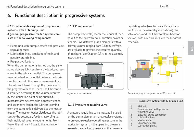
Page 55 EN
6. Functional description in progressive systems
6.1.2 Pressure regulating valve
A pressure regulating valve must be installed
on the pump element on progressive systems
to prevent excessive operating pressure in the
lubrication system. If the operating pressure
exceeds the cracking pressure of the pressure
6.1 Functional description of progressive
systems with KFG pump unit
A general progressive feeder system con-
sists of the following components:
• Pump unit with pump element and pressure
regulating valve
• Lubrication lines, consisting of main and
possibly branch lines
• Progressive feeders
When the pump motor is turned on, the piston
pump delivers lubricant from the lubricant res-
ervoir to the lubricant outlet. The pump ele-
ment attached to the outlet delivers the lubri-
cant further, into the downstream main line.
The lubricant flows through the main line to
the progressive feeder. There, the lubricant is
distributed according to the volume required
by the lubrication point being supplied.
In progressive systems with a master feeder
and secondary feeder, the lubricant coming
from the pump unit is delivered to the master
feeder. The master feeder distributes the lubri-
cant to the secondary feeders according to
their individual volume requirements. From
there, the lubricant flows to the lubrication
points.
6.1.1 Pump element
The pump element(s) meter the lubricant then
pass it to the downstream lubrication points or
feeders. Five different pump elements with a
delivery volume ranging from 0.8 to 5 cm3/min.
are available to provide the required quantity
of lubricant (see Chapter 4.3.4 in the assembly
instructions).
Progressive system with KFG pump unit
1 KFG unit 2 Pump element with pressure regulating valve 3 Electrical pump connection4 Lubrication lines 5 Master feeder 6 Secondary feeder7 Lubrication points
Example of progressive system with KFG pump unit
2
3
76 6
5
4
4
4
1
Layout of pump elements
regulating valve (see Technical Data, Chap-
ter 4.3.5 in the assembly instructions), the
valveopensandthelubricantlowsback(onversions with a return line) into the lubricant
reservoir.
6. Functional description in progressive systems
KFG

Page 56 EN
6.2. Functional description in progressive
systems with KFGS pump unit
The general functional description for progres-
sive systems with a KFG pump unit also applies
for the design with KFGS pump control.
The control unit integrated into the pump
housing allows the following additional con-
iguration,monitoringandconnectivityoptions: I nterval time and pump cycle time can
be adjusted independently, including on
monitored systems
Recording of remaining intervals and
remaining lubrication times
Data backup in case of voltage failure
Non-volatile memory with PIN code
protection
Connectivity for inductive piston detector
to monitor the feeder function
Connectivity for external pushbutton
Internalilllevelmonitoring(W1control);lubrication cycle is halted and a fault sig-
nalisdisplayediftheilllevelfallsbelowminimum
Diagnostics memory
Example of progressive system with KFGS pump unit
2
3
4
6
9
8 8
7
5
55
1
Progressive system with piston detector
1 KFGS unit 6 Piston detector
2 Power supply 7 Master feeder
3 Fault indicator light 8 Secondary feeder
4 Pump element with pressure regulating valve 9 Lubrication points
5 Lubrication lines
6. Functional description in progressive systemsK
FG
S

Page 57 EN
6.3 Functional description of progressive
system with KFGC (CAN bus) pump unit
The general functional description for pro-
gressive systems with a KFGS pump unit also
applies for the design with CAN bus pump
control.
The integrated LC-CAN 5000 control unit
permits the lubrication zone of a progressive
feeder system to be distributed into individual
lubricationzoneswhichcanbeconiguredwithindividual parameters (e.g., contact and inter-
val times). Up to four lubrication zones can be
installed in total.
To distribute the lubricant, a corresponding
number of electric switch valves is installed in
the lubrication line leading from the pump ele-
ment. A valve is opened as soon as the control
unit starts a pump cycle for the corresponding
lubrication zone.
The pump can only provide adequate lubrica-
tion to one lubrication zone at a time, so it
must be ensured that only one valve is opened
during operation. This is handled by the control
unit in automatic and semiautomatic opera-
tion.
When CAN commands are used for control,
valve opening must be ensured by selecting
the appropriate contact and interval times or
by using appropriately programmed processes
in the external lubrication program to switch
the valves in a carefully coordinated sequence
so that only one valve is activated at a time.
6.3.1 Explanations of the lubrication pro-
cess and lubrication cycle
The lubrication cycle/process is divided into a
pump cycle time and an interval time because
the lubrication points only require lubrication
at certain intervals. A lubrication cycle always
begins with a pump cycle.
Progressive system with KFGC (CAN bus) pump unit
KFG
C
CAN-Bus (SAE J1939)
6. Functional description in progressive systems
KFG
C

Page 58 EN
Pump cycle time
The pump cycle time is the time during which
the pump delivers lubricant. When multiple
lubrication zones are used, one of the zone
valves is opened and then closed once the
pump cycle ends.
The duration of the pump cycle time is a time
valueconigurableinhours,minutesandsec-
onds. The pump cycle time for units with W1
illlevelcontrolcanalsobesetinpulses,i.e.,the number of agitator revolutions. The quan-
tity of lubricant to be delivered is thus largely
independent of ambient conditions.
It is also possible to limit the pump cycle time
based on the pulses (strokes) received from
the piston detector.
Thepumpunitswitchesoffafterthedeinednumber of pulses (strokes) is reached. The
pulsesmustbereceivedwithinadeinedpe-
riod of time, otherwise the pump unit switches
to block operation.
Interval time
During an interval time, also called interval for
short, the pump is idle or, if multiple lubrica-
tion zones are used, the valve for the lubrica-
tion zone in question is closed.
The duration of the interval time can be
conigured.In automatic mode, the interval time can be
determined in two different ways: by specify-
ing either a time value (interval timer) or a
number of pulses (interval counter) sent to the
control unit by the machine depending on how
long it has been running. This provides two
different means of control: timer mode and
counter mode.
In semi-automatic mode, the user sets the
interval between two lubrications.
Whenconiguringthelubricationscenario,the interval time is a delay for consecutively
opening the valves of the individual lubrica-
tion zones after a lubrication cycle has been
started. This prevents all valves from opening
at the same time.
Block operation, pump delay time
and waiting time
On systems with piston detector monitoring,
there may be various non-critical reasons for
the set number of piston detector signals not
being received during the pump cycle time. In
this case, a second pump cycle time is started
after a certain delay.
This process can be repeated multiple times.
This process is also referred to as block opera-
tion, as the pump starts and stops quickly
several times.
Block operation is interrupted as soon as the
set number of piston detector signals has
been received. The length of an interval time
following a successful block operation is not
changed. Operation continues as normal.
If the set number of piston detector signals is
not reached during block operation, the control
unit switches off the affected lubrication zone
or the entire lubrication system and issues a
faultnotiication.The number of blocks to be cycled through can
beconigured.
6. Functional description in progressive systemsK
FG
C

Page 59 EN
6.3.2 Modes of operation
The lubrication process can be controlled
either automatically, semi-automatically or
completely via CAN commands.
6.3.2.1 Automatic control
In this operating mode, the control unit
handles all control and monitoring of the
lubrication process. The pump motor and
valves cannot be controlled using CAN com-
mands. Only the CAN command START/STOP
is allowed.
The control unit controls the following func-
tions based on the set parameters:
Starting and switching off the pump
Opening and closing the valves of the
lubrication zones
The interval time and pump cycle time are
the most important parameters for controlling
these processes. They can be set in different
ways.
Timer mode
In timer mode, the interval time for each lubri-
cation zone is determined by a time value. It is
coniguredbyenteringatimevalueinminutesand/or hours.
The pump cycle time for each lubrication zone
isconiguredusingatimevalueinhours,minutes and seconds. The pump cycle time for
unitswithW1illlevelcontrolcanalsobesetin pulses, i.e., the number of agitator revolu-
tions.
Control using machine pulses
(Counter mode = load-dependent lubrication)
The duration of the interval time is determined
by a pulse generator that sends pulses to the
control unit based on how long the machine
has been running. The control unit counts the
pulses that are received and starts the pump
or opens the corresponding zone valve after
the preset number of pulses. The pump cycle
timeisdeinedbyatimevalue.Boththenum-
ber of pulses that determine the interval time
andthepumpcycletimecanbeconigured.
When multiple lubrication zones are used,
multiple zone valves may be addressed at the
same time in automatic mode (given the cor-
responding parameters) or in block operation.
In this case, the control unit opens the valves
in a carefully coordinated sequence so that
only one valve is activated at a time, while still
providing all feeders with lubrication. The re-
sult is that the pump cycle time for each zone
is maintained.
6. Functional description in progressive systems
KFG
C
Page 60 EN
6.3.2.2 Semi-automatic control unit
In this operating mode, every lubrication cycle
must be started by a CAN START command.
When the control unit receives the START
command,thelubricationscenarioconiguredin the selected parameter set is loaded and
processed.
Thevalveforthelubricationzoneconiguredinthe parameter set as the start zone is opened.
The valves for the other zones are opened
afteradelay,whichisconiguredas"intervaltime." If interval times are the same in multiple
zones, the valves are actuated according to the
numericalsequenceconigured.Thispreventsthe pump from having to supply multiple lu-
brication zones at the same time. If the pump
cycle times for multiple zones still overlap, e.g.,
in block operation, the control unit actuates the
zones as described in the preceding section.
The pump cycle time for each zone is based on
timeorpulsesandisconiguredbyenteringthe time in hours,
minutes and seconds or a number of pulses
(corresponding to revolutions of the pump's
agitator).
The lubrication cycle can only be aborted using
a CAN STOP command. If a new lubrication
cycle is started by a CAN START command
while another lubrication process is ongoing,
the ongoing process is aborted and the new
process is started.
The system stops after completion of the lubri-
cation cycle. The next lubrication cycle must be
initiated by another CAN command.
6.3.2.3 Control via CAN commands
In this operating mode, both the pump motor
and the lubrication zone valves can be con-
trolled as desired via CAN commands. Interval
andpumpcycletimeswhichareconiguredinthe parameter sets are ignored.
When multiple lubrication zones are used,
care must be taken that multiple valves are
not opened at the same time during a pump
cycle, as this can result in undersupply of the
lubrication points.
6. Functional description in progressive systemsK
FG
C

Page 61 EN
6.3.3 Monitoring functions
The following functions are available for moni-
toring the lubrication system:
Fill level monitoring
Monitoring the lubrication cycle via
piston detector
Monitoring signal cables for cable
breakage and monitoring valves and
piston detectors
Monitoring switch outputs for short circuit
Monitoring power consumption of the
pump motor
Monitoring the temperature in the
pump unit
Diagnostics memory (real-time)
6.3.3.1 System monitoring
This function includes the following monitoring
functions:
• Fill level monitoring
• Monitoring the lubrication cycle
via piston detector
System monitoring can be activated and
deactivated. The monitoring functions men-
tioned above are deactivated when system
monitoring is deactivated. This means that no
faultnotiicationisissuedif,forexample,theilllevel in the lubricant reservoir falls below the
"min" mark.
It only makes sense to deactivate system
monitoring if the functions mentioned above
cannot be used because the required sensors
are not connected.
6.3.3.2 Fill level monitoring
Depending on the lubricant, either mechanical
or capacitive sensors are used to monitor the
illlevelinthelubricantreservoir.Inthestan-
dard design, a mechanical sensor (W1 or W1G)
monitors whether the lubricant falls below the
"min." mark. This is preferred for use with
greases of NLGI Grade 2.
ForNLGIGrade≤1greases,acapacitivesen-
sor (W2) is provided which is integrated into
the reservoir cover. The sensor sends a signal
to the control unit if the lubricant level reaches
the "min" mark. The control unit then gener-
atesafaultnotiication(seeChapter15).Faultnotiicationsduetoinsuficientilllevelareonlyissuedwhensystemmonitoring is active.
6. Functional description in progressive systems
KFG
C
Page 62 EN
6.3.3.3 Monitoring lubrication cycle via
piston detector
The progressive feeders installed on the lubri-
cation system are supplied with lubricant sev-
eral times during the pump cycle. They then
deliver the lubricant to the lubrication point.
The complete piston movement of a progres-
sive feeder forward and back to the normal
position is also called a cycle. The piston move-
ment can be detected via a contact switch,
a "piston detector," which sends the corre-
sponding signals to the control unit. There, the
signals are registered and evaluated.
The number of cycles which must occur before
anintervaltimeisstartedcanbespeciiedin order to monitor the lubrication cycle and
ensuresuficientlubricationofthelubricationpoints.
Aconigurationsettingalsodetermineswhether the pump cycle should be ended after
thespeciiednumberofpistondetectorpulseshas been reached or whether the pump should
continuetooperateuntilthespeciiedtimevalue or number of pulses (revolutions of the
agitator) is reached.
Ifthespeciiednumberofpistondetectorpulses is not reached during the pump cycle,
the control unit reacts by starting block opera-
tion.
In contrast with the KFGS pump unit, the KFGC
(CAN bus) design can repeat the lubrication
cycle as often as desired.
Ifthespeciiednumberofpulses(strokes)isreached during the repeat lubrication cycle, the
pump unit switches back to normal operation.
If the set number of piston detector signals is
not reached during block operation, the control
unit switches off the affected lubrication zone
or the entire lubrication system and issues a
faultnotiication.(seeChapter15.2).
6.3.3.4 Monitoring signal cables for cable
breakage and monitoring valves and
piston detectors
Everysignalinputconiguredforconnectingapiston detector to the control unit is constantly
monitored for cable breakage.
On a lubrication system with multiple zones,
the piston detector assigned to a zone is
queried before the zone valve is opened. If the
piston detector is not found, the control unit
assumes a cable has been broken. In this case,
thelubricationcycleisirststartedaccordingtothespeciiedpumpcycletime.Thelubricationzone is then deactivated until the piston detec-
tor fault is resolved.
Block operation is not initiated.
On a system without multiple lubrication
zones, the unit is fully deactivated after the
pumpcycletimeisinished.Afaultnotiicationisgeneratedinallcases(seeChapter 15.2).
6. Functional description in progressive systemsK
FG
C

Page 63 EN
The signal inputs can be linked to the outputs.
This allows indirect monitoring of whether
a valve attached to the output has actually
opened to allow lubricant through. The inputs
and outputs must be clearly assigned. A signal
input used to, for example, operate a cycle
switch can only monitor the valve of the lubri-
cation zone that contains the piston detector.
6.3.3.5 Monitoring switching outputs for
short circuits
The control unit is capable of detecting short
circuit faults on the outputs. In such cases, the
output is switched off, which idles the cor-
respondingvalve,andafaultnotiicationisgenerated.
Unaffected valves continue to operate.
6.3.3.6 Monitoring power consumption of
the pump motor
The power consumption of the pump motor
is monitored to avoid motor overload. If the
limit values are exceeded (see Technical Data,
Chapter 4.5.1 in the assembly instructions),
the system is switched off and enters fault
mode (see Chapter 15.2).
6. Functional description in progressive systems
KFG
C

Page 64 EN
6.3.5 Conigurable parametersThe control unit contains 16 pre-set sets of
parameter data which can be programmed
as desired. A parameter set contains all the
information required to control and monitor
the lubrication process, e.g., the number of
lubrication zones, the interval times, the pump
cycle times, the number of cycles, etc.
6.3.4 Display and documentation functions
During system operation, current operational
data (status data) is stored in the FRAM and
can be read at any time.
If the control unit is switched off or loses
power, the most recent status data remains in
the FRAM. When the control unit is turned on
again, it reads the saved data and the lubrica-
tion process continues where it left off, unless
theconigurationhasbeenchanged(zerovoltage signal).
All faults detected by the lubrication system's
monitoring functions are also given a time
stamp and stored persistently in the control
unit's non-volatile memory area.
6.3.3.7 Monitoring unit temperature
The printed circuit board of the LC-CAN 5000
control unit contains a temperature sensor. If
the temperature in the unit exceeds the limit
value (see Technical Data, Chapter 13), the
system is switched off and enters fault mode
(see Chapter 11).
6. Functional description in progressive systemsK
FG
C
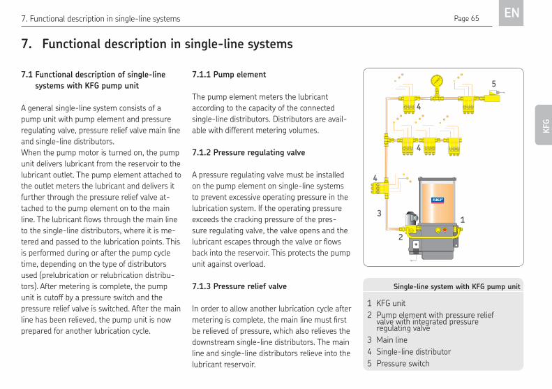
Page 65 EN
7. Functional description in single-line systems
7. Functional description in single-line systems
7.1.3 Pressure relief valve
In order to allow another lubrication cycle after
meteringiscomplete,themainlinemustirstbe relieved of pressure, which also relieves the
downstream single-line distributors. The main
line and single-line distributors relieve into the
lubricant reservoir.
7.1 Functional description of single-line
systems with KFG pump unit
A general single-line system consists of a
pump unit with pump element and pressure
regulating valve, pressure relief valve main line
and single-line distributors.
When the pump motor is turned on, the pump
unit delivers lubricant from the reservoir to the
lubricant outlet. The pump element attached to
the outlet meters the lubricant and delivers it
further through the pressure relief valve at-
tached to the pump element on to the main
line. The lubricant flows through the main line
to the single-line distributors, where it is me-
tered and passed to the lubrication points. This
is performed during or after the pump cycle
time, depending on the type of distributors
used (prelubrication or relubrication distribu-
tors). After metering is complete, the pump
unit is cutoff by a pressure switch and the
pressure relief valve is switched. After the main
line has been relieved, the pump unit is now
prepared for another lubrication cycle.
7.1.1 Pump element
The pump element meters the lubricant
according to the capacity of the connected
single-line distributors. Distributors are avail-
able with different metering volumes.
7.1.2 Pressure regulating valve
A pressure regulating valve must be installed
on the pump element on single-line systems
to prevent excessive operating pressure in the
lubrication system. If the operating pressure
exceeds the cracking pressure of the pres-
sure regulating valve, the valve opens and the
lubricantescapesthroughthevalveorlowsback into the reservoir. This protects the pump
unit against overload.
Single-line system with KFG pump unit
1 KFG unit
2 Pump element with pressure relief valve with integrated pressure regulating valve
3 Main line
4 Single-line distributor
5 Pressure switch
5
3
2
1
4
4
4
KFG

Page 66 EN 7. Functional description in single-line systems
7.2 Functional description of single-line
system with KFGS pump unit
The general functional description for single-
line systems with a KFG pump unit also applies
for the design with KFGS pump control.
The control unit integrated into the pump
housing allows the following additional con-
iguration,monitoringandconnectivityoptions: Interval time and pump cycle time can be
adjusted independently, including on
monitored systems
Recording of remaining intervals and
remaining lubrication times
Recordingoffaultnotiications
(diagnostics memory)
Data backup in case of voltage failure
Non-volatile memory with PIN code
protection
Connectivity for pressure switch
Fill level monitoring, lubrication cycle is
stoppedandfaultnotiicationshownon display in case level falls below minimum
3 4
5
1
2
M
6
Legend to figure of KFGS single-line system
1 Pumpunitwithpumpelementandilllevelmonitoring2 Pressure regulating valve
3 Valve for pressure build-up and relief
4 Single-line distributor
5 Pressure gauge for pressure build-up monitoring (optional)
6 Pressure switch for pressure build-up monitoring
Single-line system with a lubrication zone using a 3/2 directional solenoid valve
KFG
S

Page 67 EN
7.3. Functional description in single-line
systems with KFGC (CAN bus)
pump unit
The general functional description for single-
line systems with a KFG pump unit also applies
for the design with CAN bus pump control.
7.3.2 Multiple lubrication zones
Using the integrated LC-CAN 5000
control unit, a single-line system can be
divided into up to four individually controllable
lubrication zones. This is performed using
electric switch valves which separate the indi-
vidual lubrication zones from each other.
Fourconigurabledigitalinputs/outputsareavailable to control each lubrication zone. This,
as well as the type of valves used, provides
various possibilities for setting up lubrication
zones.
7.3.1 Systems with directional
solenoid valves
Directional solenoid valves can be used to
create a single-line system with up to four
lubrication zones. The system can be equipped
with or without functionality to monitor pres-
sure build-up and reduction.
Note
Dependingontheieldofapplicationandthesystem design, a compact 5/4 directional
solenoid valve can be used in place of individual
3/2 directional solenoid valves.
Legend
1 Pump unit with pump element and illlevelmonitoring2 Pressure regulating valve Lubrication string of line 1/2/3
3 Valve for pressure build-up and relief
4 Single-line distributors
5 Pressure switch for pressure build-up monitoring
M
Lubrication string of line 1
Lubrication string of line 2
Lubrication string of line 3
1CAN KFG
2
3
3
3
4
4
4
5
5
5
Single-line system with three lubrication zones using directional solenoid valves
7. Functional description in single-line systems
KFG
C

Page 68 EN
7.3.3 Control unit
Explanations of the lubrication process
A differentiation is made between lubrication
cycles with and without pressure build-up
monitoring.
Lubrication cycle without pressure build-up
monitoring
On single-line systems without pressure build-
up monitoring, the lubrication cycle consists of
a pump cycle time and an interval time.
Lubrication cycle with pressure build-up
monitoring
On systems with pressure build-up monitor-
ing (see Chapter 6.3.3.3), the lubrication cycle
is divided into the pump cycle time, the pump
delay time and the interval time.
A lubrication cycle always begins with a pump
cycle.
Pump cycle time on systems without
pressure build-up monitoring
During the pump cycle time, the system
pressure required for lubrication is built up in
the lubrication line. When multiple lubrication
zones are used, the inlet valve of the relevant
lubrication zone is opened at the start of the
pump cycle time. The associated pressure
relief valve is closed.
Change-over can alternately be performed via
a 3/2 directional solenoid valve instead of the
two required 2/2 directional solenoid valves.
Oncethepumpcycletimeisinished,thepump is switched off and the pressure relief
valve is opened. When multiple lubrication
zones are used, the corresponding inlet valve
is closed at the same time.
The duration of the pump cycle time is a time
valueconigurableinhours,minutesandseconds. The pump cycle time for units with
W1illlevelcontrolcanalsobesetinpulses,i.e., the number of agitator revolutions. Die
abzugebende Schmiermenge
The quantity of lubricant to be delivered is
thus independent of ambient conditions.
Pump cycle time and pump delay time on
systems with pressure build-up
monitoring
The pressure switch monitors whether the
required pressure buildup occurs in the lubri-
cation line during the pump cycle time. If the
pressure (switching point) set on the pressure
switch is reached, the control unit receives the
switching signal from the pressure switch and
then ends the pump cycle time. The pump
delay time is started at the same time.
The pump delay time is necessary in order to
maintain pressure in the lubrication lines until
all distributors have delivered the lubricant.
There is no interruption between the pump
cycle time and the pump delay time.
If the pressure value set on the pressure
switchisnotreachedduringthespeciiedpump cycle time, the pump is switched off and
afaultnotiicationisgenerated.Thepumpdelaytimeisatimevalueconigu-
rable in hours, minutes and seconds.
7. Functional description in single-line systemsK
FG
C
Page 69 EN
Interval time
During an interval time, also called interval for
short, the pump is idle or, if multiple lubrica-
tion zones are used, the inlet valve for the
lubrication zone in question is closed.
The duration of the interval time can be
conigured.In automatic mode (see Chapter 6.3.2.1), the
interval time can be determined in two dif-
ferent ways: by specifying either a time value
or an external number of pulses sent to the
control unit by the machine depending on how
long it has been running. This provides two
different means of control: timer mode and
counter mode.
7.3.3.1 Modes of operation
The lubrication process can be controlled
either automatically, semi-automatically or
completely via CAN commands.
Automatic control
In this operating mode, the control unit
handles all control and monitoring of the
lubrication process. The pump motor and
valves cannot be controlled using CAN com-
mands. Only the CAN command START/STOP
is allowed.
The control unit controls the following func-
tions based on the set parameters:
Starting and switching off the pump
Opening and closing the valves of the
lubrication zones
The interval time and pump cycle time are
the most important parameters for controlling
these processes. They can be set in different
ways.
Timer mode
In timer mode, the interval time for each lubri-
cation zone is determined by a time value. It is
coniguredbyenteringatimevalueinminutesand/or hours.
Thepumpcycletimeisconiguredforeachlubrication zone using a time value in hours,
minutes and seconds. The pump cycle time for
unitswithW1illlevelcontrolcanalsobesetin pulses, i.e., the number of agitator revolu-
tions.
Control using machine pulses
(Counter mode = load-dependent lubrication)
The duration of the interval time is determined
by a pulse generator that sends pulses to the
control unit based on how long the machine
has been running. The control unit counts the
pulses that are received and starts a pump
cycle after the preset number of pulses. Both
the number of pulses that determine the
interval time and the pump cycle time can be
conigured.When multiple lubrication zones are used,
multiple zone valves may be addressed at the
same time in automatic mode.
7. Functional description in single-line systems
KFG
C

Page 70 EN
In this case, the control unit opens the valves
in a carefully coordinated sequence so that
only one valve is activated at a time, while still
providing all feeders with lubrication. The re-
sult is that the pump cycle time for each zone
is maintained.
7.3.3.2 Semi-automatic control
In this operating mode, every lubrication cycle
must be started by a CAN command.
When the control unit receives the START
command,thelubricationscenarioconiguredin the selected parameter set is loaded and
processed.
Thevalveforthelubricationzoneconiguredinthe parameter set as the start zone is opened.
The valves for the other lines are opened after
adelaywhichwasconiguredas"intervaltime." If interval times are the same in multiple
lines, the valves are actuated according to the
numericalsequenceconigured.Thispreventsthe pump from having to supply multiple lu-
brication zones at the same time. If the pump
cycle times for multiple lines still overlap, the
control unit actuates the zones as described in
the preceding section.
The pump cycle time for each zone is time-
dependentandisconiguredbyenteringatime value in hours, minutes and seconds.
ThepumpcycletimeforunitswithW1illlevel control can also be set in pulses, i.e., the
number of agitator revolutions.
The lubrication cycle can only be aborted using
a CAN STOP command. If a new lubrication
cycle is started by a CAN START command
while another lubrication process is ongoing,
the ongoing process is aborted and the new
process is started.
The system stops after completion of the lubri-
cation cycle. The next lubrication cycle must be
initiated by another CAN command.
7.3.3.3 Control via CAN commands
In this operating mode, both the pump mo-
tor and the lubrication zone valves can be
controlled as desired via CAN commands. Any
parameter values that have been programmed
for interval and pump cycle times are ignored.
When multiple lubrication zones are used,
care must be taken that multiple valves are
not opened at the same time during a pump
cycle, as this can result in undersupply of the
lubrication points.
7. Functional description in single-line systemsK
FG
C

Page 71 EN
7.3.4 Monitoring functions
The following functions are available for moni-
toring the lubrication system:
Fill level monitoring
Pressure build-up monitoring
Pressure reduction monitoring
Monitoring signal cables for
cable breakage and monitoring valves and
piston detectors
Monitoring outputs for short circuit
Monitoring power consumption of the
pump motor
Monitoring the temperature in the
pump unit
7.3.4.1 Fill level monitoring
Depending on the unit design, either mechani-
cal or capacitive sensors are used to monitor
theilllevelinthelubricantreservoir.Onunitswithilllevelmonitoring,amechanicalsensormonitorswhethertheilllevelfallsbelowthe"min." mark (approx. 300 g remaining for NLGI
Grade 2 grease). A second, optional sensor
can be used to generate a pre-warning so the
operator is prompted to top up in time.
The sensor sends a signal to the control unit if
the lubricant level reaches the "min" mark. The
controlunitthengeneratesafaultnotiication(see Chapter 15).
7.3.4.2 Pressure build-up monitoring
(single-line systems)
The pressure switch monitors whether the re-
quired pressure buildup occurs in the lubrica-
tion line during the pump cycle time. A signal is
sent to the control unit when the set pressure
is reached. The signal from the pressure switch
can be used to control the pump cycle time. If
thepressureinthelinesreachesthespeciiedvalue within a certain time (pump cycle time),
the pump will continue to be operated for a
certain time (delay time) and then switched off,
or the lubrication zone will be closed and the
relief procedure initiated.
If the pressure in the lubrication line does not
reachthespeciiedvaluewithinthepumpcycle time, this is considered an operational
malfunction. The operational sequence will be
stoppedandafaultnotiicationwillbegener-ated (see also Chapter 15).
7. Functional description in single-line systems
KFG
C
Page 72 EN
7.3.4.3 Pressure reduction monitoring
(single-line systems)
The pressure reduction in the lubrication line
during the relief procedure can also be moni-
tored using a pressure switch. The signal from
the pressure switch is evaluated differently
depending on the pressure relief valve used.
When 2/2 valves are used, they are closed
once the set minimum pressure is reached in
the lubrication line. This retains a minimum
pressure in the lubrication line.
When 3/2 directional control valves are used,
the signal from the pressure switch provides
notiicationthatthelineshavebeenrelieved.Ifthis is not the case, it is considered a malfunc-
tion. The operational sequence will be stopped
andafaultnotiicationwillbegenerated(seealso Chapter 15)
When 3/2 valves are used, no minimum pres-
sure can be established in the lines, as the
valve either opens for pressure build-up or
closes the line while simultaneously relieving
it. This is not considered a problem on grease
lubrication systems.
7.3.4.4 Monitoring signal cables for cable
breakage and monitoring valves and pres-
sure switches
Everysignalinputconiguredforconnectingapressure switch to the control unit is constantly
monitored for cable breakage.
On systems with multiple lubrication zones, the
pressure switch assigned to a zone is queried
before a valve is opened. If the pressure switch
is not found, the control unit assumes a cable
has been broken. In this case, the lubrication
zone is deactivated until the pressure switch
fault is resolved.
On a system without multiple lubrication zones,
theunitisfullydeactivated.Afaultnotiicationis generated in all cases (see Chapter 15).
The signal inputs can be linked to the outputs.
This allows indirect monitoring of whether
a valve attached to the output has actually
opened to allow lubricant through. The inputs
and outputs must be clearly assigned. A signal
input used, e.g., to operate a pressure switch
can only monitor the valve of the lubrication
zone that contains the pressure switch.
7.3.4.5 Monitoring outputs for short circuit
The control unit is capable of detecting short
circuit faults on the outputs. In such cases, the
output is switched off, which idles the cor-
respondingvalve,andafaultnotiicationisgenerated.
Unaffected valves continue to operate.
7.3.4.6 Monitoring power consumption of
the pump motor
The power consumption of the pump motor
is monitored to avoid motor overload. If the
limit values are exceeded (see Technical Data,
Chapter 16), the system is switched off and
enters fault mode (see Chapter 15).
7.3.4.7 Monitoring unit temperature
The printed circuit board of the LC-CAN 5000
control unit contains a temperature sensor. If
the temperature in the unit exceeds the limit
value (see Technical Data, Chapter 16), the
system is switched off and enters fault mode
(see Chapter 15).
7. Functional description in single-line systemsK
FG
C

Page 73 EN
7.3.5 Display and documentation functions
During system operation, current operational
data (status data) is stored in the FRAM and
can be read at any time.
If the control unit is switched off or loses
power, the most recent status data remains in
the FRAM. When the control unit is turned on
again, it reads the saved data and the lubrica-
tion process continues where it left off, unless
theconigurationhasbeenchanged.All faults detected by the lubrication system's
monitoring functions are also given a time
stamp and stored persistently in the control
unit's non-volatile memory area.
7.3.6 Conigurable parametersThe control unit contains 16 sets of param-
eter data. A parameter set contains all the
information required to control and monitor
the lubrication process, e.g., the number of
lubrication zones, the interval times, the pump
cycle times, etc.
7. Functional description in single-line systems
KFG
C

Page 74 EN
8. Commissioning
The product described here functions auto-
matically. The lubricant transport in the lubri-
cation lines should, however, be subjected to
regular visual inspection.
The lubricant fill level in the lubricant reservoir,
if present, should likewise be subjected to reg-
ular visual inspection. If the lubricant fill level is
too low, lubricant needs to be added up to the
maximum mark.
Observe the instructions from the
machine manufacturer regarding the
lubricants that are to be used.
Warning!
Onlyillusingcleanlubricantandanappropriate device. Contaminated
lubricants can result in severe system
malfunction. The lubricant reservoir
mustbeilledwithoutintroducingbubbles.
Warning!
Different lubricants cannot be mixed,
as mixing may result in damage and
necessitate costly and complicated
cleaning of the product/centralized
lubrication system.
It is recommended that an indication of
the lubricant in use be attached to the
lubricant reservoir in order to prevent
accidental mixing of lubricants.
8.1 General commissioning
Before the product is commissioned, all elec-
trical connections must be inspected.
The lubricant may only be fed without bubbles.
The lubricant reservoir, if present, must be
filled with clean lubricant without introducing
bubbles. The product is then operated until lu-
bricant without bubbles is discharged at all lu-
brication points.
The process of venting the centralized lubrica-
tion system can be facilitated by:
Opening the ends of the main pipes until
lubricant without bubbles is discharged.
Filling long pipe sections before connect-
ing to the lubrication points.
8. CommissioningK
FG
SK
FG
KFG
C

Page 75 EN
9. Display and control elements of control screen
9.1 KFGS series
The display and control unit is protected from
water splashes and mechanical damage by
a transparent plastic cover. The cover must
be removed to program the unit and then
remounted afterwards.
Display and control elements of the KFGS control screen
Symbol Description Function
Three-digit LED display Values and operating status
PAUSE LED Interval time
CONTACT LED Display contact time (pump operation)
1 = CS LED Monitors system function via an external piston detector CS = Cycle Switch, piston detector 2 = PS LED Monitors function with an
external pressure switch PS = Pressure Switch
FAULT LED Fault notification
UP or DOWN key Switch on display Display values and parameters Set values and parameters
SET key Switch between programming mode and display mode Confirm values
DK key Trigger interim lubrication Delete fault notification
2
1
9. Display and control unit
Control screen
KFG
S

Page 76 EN
9.1.1 Three-digit LED display
The display is off in normal mode. It can be
activatedbybrielypressingoneofthetwopushbuttons . Current values and pre-
set parameters are displayed. The display also
serves to guide and prompt the operator while
programming operating parameters.
Device display - three-digit LED display
9. Display and control unit
Three-digit LED display
Display Meaning Statement Control function
t = TIMERPA = PAUSE
c = COUNTERPA = PAUSE
t = TIMERCO = CONTACT
c = COUNTER CO = CONTACT
C = Cycle O = OFF P = Pressure
Monitoring OFF
Cycle Switch, piston detector (progressive systems)
The control unit is functioning as a timer and is currently in PAUSE mode.
The control unit is functioning as a counter and is currently in PAUSE mode.
The control unit is functioning as a timer and is currently in a pump cycle (CONTACT).
The control unit is functioning as a counter and is currently in a pump cycle (CONTACT).
Display the "Monitoring settings" menu
The CS and PS monitoring func-tions are switched off.
Piston detector monitoring is active.
Part of lubrication cycle; entry and display value in hours.
Part of the lubrication cycle; the device counts the pulses from the external timer and compares them with the pre-set values.
CONTACT = time during which the pump delivers lubricant; entry and display value in minutes.
CONTACT = time during which the pump delivers lubricant; entry and display value in pulses.
No system monitoring
The piston detector is monitored for signals during the CONTACT pump cycle.
KFG
S
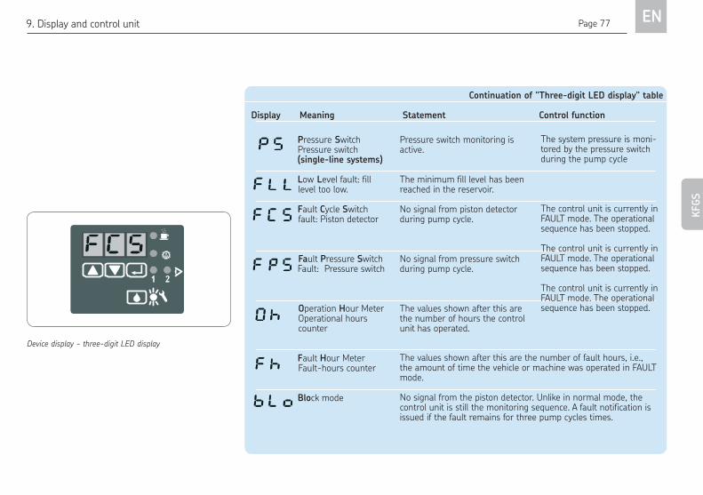
Page 77 EN
Device display - three-digit LED display
Continuation of "Three-digit LED display" table
Display Meaning Statement Control function
Pressure Switch Pressure switch(single-line systems)
Low Level fault: fill level too low.
Fault Cycle Switch fault: Piston detector
Fault Pressure SwitchFault: Pressure switch
Operation Hour Meter Operational hours counter
Fault Hour Meter Fault-hours counter
Block mode
Pressure switch monitoring is active.
The minimum fill level has been reached in the reservoir.
No signal from piston detector during pump cycle.
No signal from pressure switch during pump cycle.
The values shown after this are the number of hours the control unit has operated.
The system pressure is moni-tored by the pressure switch during the pump cycle
The control unit is currently in FAULT mode. The operational sequence has been stopped.
The control unit is currently in FAULT mode. The operational sequence has been stopped.
The control unit is currently in FAULT mode. The operational sequence has been stopped.
The values shown after this are the number of fault hours, i.e., the amount of time the vehicle or machine was operated in FAULT mode.
No signal from the piston detector. Unlike in normal mode, the control unit is still the monitoring sequence. A fault notification is issued if the fault remains for three pump cycles times.
9. Display and control unit
KFG
S

Page 78 EN
9.1.2 LED display
Device display - LED display
LED display
LED LED lights up = display mode LED flashes = programming mode
The operating voltage is present on the pump unit and control unit. The control unit is in operating status FAULT. The cause can be accessed via the LED display and shown as a fault code by pressing the pushbutton. The operational sequence has been stopped.
Value for PAUSE can be changed.
Value for CONTACT can be changed.
Monitoring type can be switched off in pro-gramming mode. COP = CS monitoring is active COP = OFF monitoring is switched off
Monitoring by pressure switch cannot be activated on progressive systems. COP = CS monitoring is activeCOP = OFF monitoring is switched off
Operating voltage is present on pump unit and control unit, system is currently in oper-ating status PAUSE
Operating voltage is present on pump unit and control unit, system is currently in oper-ating status CONTACT (pump motor ON)
A cycle switch (CS) is used for system monitoring. On progressive feeders, moni-toring is performed during the pump cycle (CONTACT).The LED lights up when a signal is received.
A pressure switch (PS) is used for system monitoring. On single-line systems, monitoring is performed during the pump cycle.The LED lights up when a change-over signal is received.
2
1
CS
PS
9. Display and control unit K
FG
S

Page 79 EN
9.1.3 Pushbutton operation Pushbutton operation
Key Function
Pressing during PAUSE triggers an interim lubrication. Fault notifications are acknowledged and deleted.
Switch on the display in display mode Call up next parameter in programming mode Increase displayed value by 1
Switch on the display in display mode Call up last parameter in programming mode Reduce displayed value by 1
Switch between programming mode and display mode Confirm values entered
Device display - pushbuttons
9. Display and control unit
KFG
S
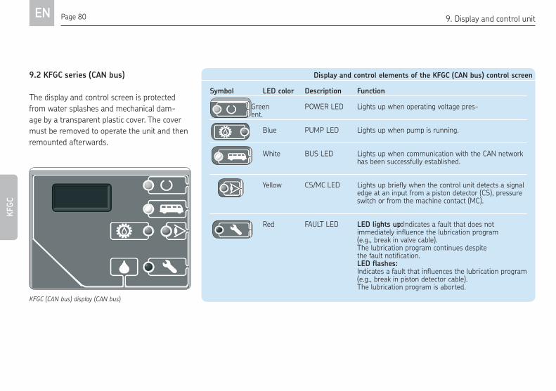
Page 80 EN
9.2 KFGC series (CAN bus)
The display and control screen is protected
from water splashes and mechanical dam-
age by a transparent plastic cover. The cover
must be removed to operate the unit and then
remounted afterwards.
Display and control elements of the KFGC (CAN bus) control screen
Symbol LED color Description Function
Green POWER LED Lights up when operating voltage pres-ent.
Blue PUMP LED Lights up when pump is running.
White BUS LED Lights up when communication with the CAN network has been successfully established.
Yellow CS/MC LED Lights up briefly when the control unit detects a signal edge at an input from a piston detector (CS), pressure switch or from the machine contact (MC).
Red FAULT LED LED lights up:Indicates a fault that does not immediately influence the lubrication program (e.g., break in valve cable). The lubrication program continues despite the fault notification. LED flashes: Indicates a fault that influences the lubrication program (e.g., break in piston detector cable). The lubrication program is aborted.
KFGC (CAN bus) display (CAN bus)
9. Display and control unit K
FG
C

Page 81 EN
Continuation of "Display and control elements of the KFGC (CAN bus) control screen" table
Symbol Description Function
IrDA interface Infrared service interface Read stored status data and fault notifications Configure the control unit via PC
DK key Trigger interim lubrication Halt lubrication Delete fault notification
KFGC (CAN bus) display (CAN bus)
9. Display and control unit
KFG
C
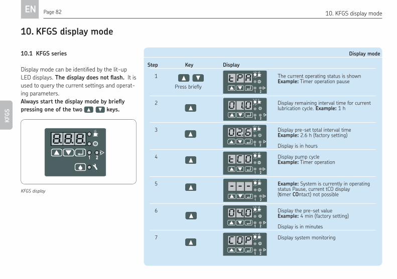
Page 82 EN
10. KFGS display mode
10.1 KFGS series
Displaymodecanbeidentiiedbythelit-upLED displays. The display does not lash. It is
used to query the current settings and operat-
ing parameters.
Always start the display mode by briely pressing one of the two keys.
Display mode
Step Key Display
1 The current operating status is shown Example: Timer operation pause Press briefly
2 Display remaining interval time for current lubrication cycle. Example: 1 h
3 Display pre-set total interval time Example: 2.6 h (factory setting) Display is in hours
4 Display pump cycle Example: Timer operation
5 Example: System is currently in operating status Pause, current tCO display (timer COntact) not possible
6 Display the pre-set value Example: 4 min (factory setting) Display is in minutes
7 Display system monitoring
KFGS display
10. KFGS display modeK
FG
S
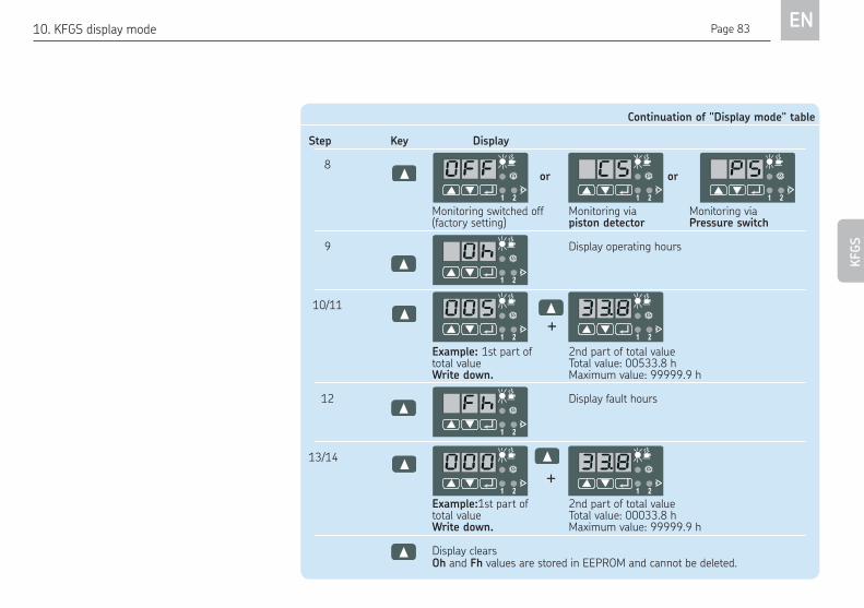
Page 83 EN
Continuation of "Display mode" table
Step Key Display
8 or or Monitoring switched off Monitoring via Monitoring via (factory setting) piston detector Pressure switch
9 Display operating hours
10/11 Example: 1st part of 2nd part of total value total value Total value: 00533.8 h Write down. Maximum value: 99999.9 h
12 Display fault hours
13/14 Example:1st part of 2nd part of total value total value Total value: 00033.8 h Write down. Maximum value: 99999.9 h
Display clears Oh and Fh values are stored in EEPROM and cannot be deleted.
10. KFGS display mode
KFG
S
+
+

Page 84 EN
11.1 Start programming mode
ProgrammingmodecanbeidentiiedbythelashingLEDdisplays.
11.2 Change lubrication interval times
Note on step 2
If the 000 factory setting has been
changed, the current code must be
selected using the keys and
conirmedusingthe key.
Change lubrication interval times
Step Key Display
1 Display flashes (000 = factory setting) Press for more than 2 s
2 Automatic display of first parameter: "pause in timer operation" Press briefly "PAUSE" LED flashes (confirm code)
3 Interval time 1 h (factory setting) (display in hours) Press briefly
4 Set new value Example: 6.8 h = 6 h 48 min
5 Display next parameter "pump cycle time in timer operation" Press briefly "CONTACT" LED flashes (confirm new value)
6 Pump cycle time 4.0 min (factory setting) Note the operating mode/set duration Press briefly - see Technical Data, Chapter 16 (display in minutes)
The working/interval times can be repro-
grammed to adapt the lubrication intervals and
theresultinglubricantquantitiestospeciicrequirements.
11. KFGS programmingK
FG
S
11. KFGS programming

Page 85 EN11. KFGS programming
Continuation of "Change lubrication interval times" table
Step Key Display
7 Set new value
8 Press briefly (confirm new value)
9 Changes are written to memory, the values are activated and Press for more than 2 s the display clears
KFG
S
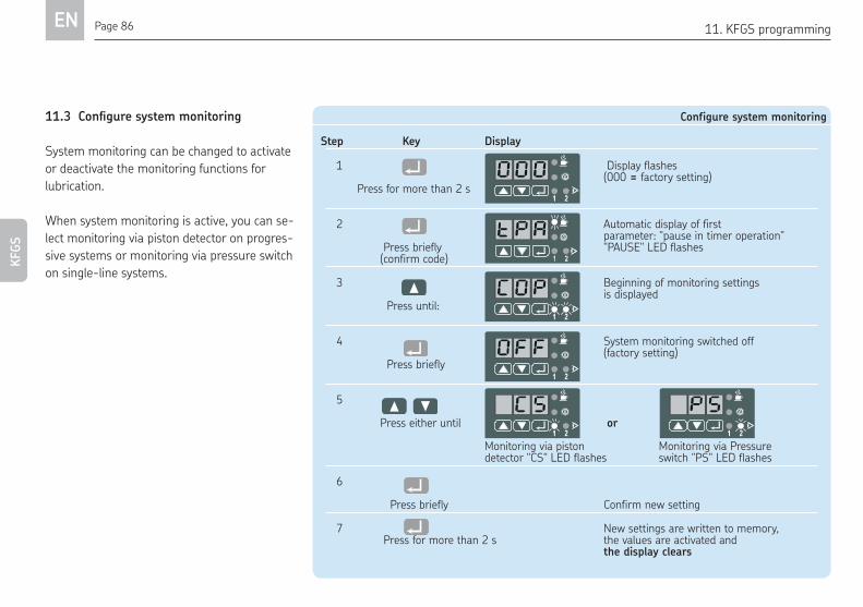
Page 86 EN
11.3 Conigure system monitoring Configure system monitoring
Step Key Display
1 Display flashes (000 = factory setting) Press for more than 2 s
2 Automatic display of first parameter: "pause in timer operation" Press briefly "PAUSE" LED flashes (confirm code)
3 Beginning of monitoring settings is displayed Press until:
4 System monitoring switched off (factory setting) Press briefly
5 Press either until or Monitoring via piston Monitoring via Pressure detector "CS" LED flashes switch "PS" LED flashes
6 Press briefly Confirm new setting
7 New settings are written to memory, Press for more than 2 s the values are activated and the display clears
System monitoring can be changed to activate
or deactivate the monitoring functions for
lubrication.
When system monitoring is active, you can se-
lect monitoring via piston detector on progres-
sive systems or monitoring via pressure switch
on single-line systems.
11. KFGS programmingK
FG
S

Page 87 EN
11.4 Change operating modes Change operating mode
Step Key Display
1 Display flashes (000 = factory setting) Press for more than 2 s
2 Automatic display of first Press briefly parameter: "pause in timer operation" (confirm code) "PAUSE" LED flashes
3 Change from interval time to counter operation (only possible with external electrical pulse generator) Values in pulses
4 Display pump cycle time in timer operation Press briefly to confirm counter operation
5 Change from pump cycle time to counter operation, special application
6 Confirm new setting Press briefly
7 New settings are written to memory, and the display clears Press for more than 2 s
A change of operation mode means changing to
timer operation, counter operation or special ap-
plications.
Please refer to Chapter 12 for further information.
11. KFGS programming
KFG
S

Page 88 EN
Change code
Step Key Display
1 Display flashes (000 = factory setting) Press for more than 2 s
2 key number is selected Press briefly (321 = factory default setting) (confirm code)
3 Display flashes Press briefly (confirm key) (000 = factory setting)
4 Press briefly Display flashes (confirm code)
5 new code is set Press either until Warning! Do not enter 321
6 Press briefly Confirm new code
7 New code is written to memory Press for more than 2 s and the display clears
11.5 Change access code
This factory default code is now deleted
and the new value is valid. Write down
the new value and store it in a safe
place. The parameters cannot be pro-
grammed if the code is lost or forgotten.
In this case, the pump unit must be
sent to the dealer or authorized SKF
branchofice.Warning!
Do not enter the digits 321 as the
new code.
11. KFGS programmingK
FG
S

Page 89 EN
11.6 Programming ranges 11.7 Display ranges
Programming ranges
Function Programming range 1)
Interval time 0.1 h to 99.9 h Pump cycle time 0.1 min to 99.9 min Pulses 1 to 999
Display ranges
Function Display range
Fault hours 0.1 h to 99999.9 h
Operating hours 0.1 h to 99999.9 h
1) For the permissible setting range for KFG(S) 90-264 VAC, see Technical Data, Chapter 16.
11. KFGS programming
KFG
S

Page 90 EN
12.1 Timer operation
The interval and pump cycle are time-
dependent.
The lubrication cycle is controlled by the pre-
set, time-dependent values for PAUSE and
CONTACT.
PAUSE: Values in hours
CONTACT: Values in minutes
Set tPA and tCO in programming
mode.
12. KFGS operating modes
12.2 Counter operation
The interval depends on the number of pulses;
the pump cycle time is time-dependent.
An external pulse generator must be attached
as described in Chapter 4 in the assembly
instructions.
PAUSE: Values in pulses
CONTACT: Values in minutes
A switch opens and closes based on machine
movements, revolutions, etc.
A lubrication is triggered once the set number
of pulses (cPA) is reached.
Set cPA und tCO in programming
mode.
12.3 No system monitoring
In this operating mode, the lubrication cycle
is controlled solely by the pre-set values for
PAUSE and CONTACT.
Monitoring must be switched off.
COP = OFF System malfunctions are
not automatically detected or displayed.
12.4 With system monitoring
In this operating mode, system functions are
additionally monitored using external switches.
The following can be monitored:
Fill level in the lubricant reservoir
Function of progressive feeder using a
piston detector
Function of single-line system using a
pressure switch
Operational malfunctions are automati-
cally detected and displayed. Monitoring
is switched on.
COP = CS or PS.
12. KFGS operating modesK
FG
S

Page 91 EN12. KFGS operating modes
12.5 Fill level monitoring
Ifilllevelmonitoringisinstalled,itisalways active.
If the level in the lubricant reservoir falls below
theminimumilllevel,thelubricantcycleisstoppedandafaultnotiicationisissuedonthedisplay.
FLL: Fault Low Level (fill level too low)
Aunitcanonlyberetroittedfrom"without"illlevelmonitoringto"with"illlevelmonitoringinthefactory,whichrequires that it be sent to the factory for
rework.
12.6 Monitoring via piston detector
Only possible for centralized lubri-
cation systems with progressive
feeders.
For greases up to NLGI Grade 2.
The piston detector monitors the movement
of pistons in the progressive feeder during
CONTACT time (pump cycle time). The fol-
lowing monitoring setting must be activated in
programming mode:
COP = CS see Chapter 11.3
5
9
8
7
6
4
32
1
Progressive system with piston detector
1 KFGS unit 4 Fault indicator light 8 Secondary feeder
2 Pump element with 5 main lines 9 Lubrication points
Pressure regulating valve 6 Master feeder
3 Power supply 7 Piston detector
5 5
8
KFG
S
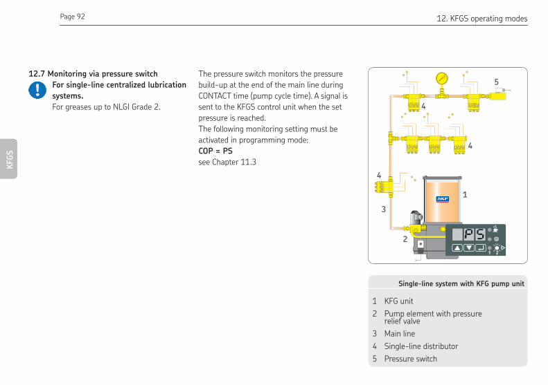
Page 92 EN 12. KFGS operating modes
12.7 Monitoring via pressure switch The pressure switch monitors the pressure
build-up at the end of the main line during
CONTACT time (pump cycle time). A signal is
sent to the KFGS control unit when the set
pressure is reached.
The following monitoring setting must be
activated in programming mode:
COP = PS
see Chapter 11.3
For single-line centralized lubrication
systems.
For greases up to NLGI Grade 2.
Single-line system with KFG pump unit
1 KFG unit
2 Pump element with pressure relief valve
3 Main line
4 Single-line distributor
5 Pressure switch
4
3
2
1
4
4
5
KFG
S
Page 93 EN
13.1 Temporary shutdown
The described product can be temporarily shut
down by disconnecting the electrical supply
connections. The instructions in the Chapter
"General information" in these assembly in-
structions must be observed when doing so.
If the product is to be shut down for an extend-
ed period of time, follow the instructions in the
Chapter "Transport, delivery, and storage" of
these assembly instructions.
To recommission the product, follow the in-
structions in the Chapter "Assembly".
13. Shutdown
13.2 Permanent shutdown
If the product will be permanently shut down,
the local regulations and laws regarding the
disposal of contaminated equipment must be
observed.
Warning!
Lubricants can contaminate soil and
bodies of water. Lubricants must be
properly used and disposed of. Observe
the local regulations and laws regarding
the disposal of lubricants.
The product can also be returned to SKF
Lubrication Systems Germany GmbH for dis-
posal, in which case the customer is respon-
sible for reimbursing the costs incurred.
13. Shutdown
KFG
SK
FG
KFG
C
Page 94 EN
14. Maintenance
Danger!
Work on products that have not been
de-energized may result in bodily injury.
Assembly, maintenance and repair work
may only be performed on products
that have been de-energized by quali-
iedtechnicalpersonnel.Thesupplyvoltage must be switched off before
opening any of the product's compo-
nents.
Danger!
Centralized lubrication systems are
pressurized during operation. Central-
ized lubrication systems must there-
fore be depressurized before starting
assembly, maintenance or repair work,
oranysystemmodiicationsorsystemrepairs.
Danger!
The described product is pressurized
during operation. The product must
therefore be depressurized before
starting assembly, maintenance or re-
pairwork,oranysystemmodiicationsor system repairs.
Products from SKF Lubrication Systems
Germany GmbH are low-maintenance.
However, all connections and fittings must be
regularly inspected for proper seating to en-
sure proper function and to prevent hazards
from arising.
If necessary, the product can be cleaned using
mild cleaning agents that are compatible with
the product's materials (non-alkaline, non-
soap). For safety reasons, the product should
be disconnected from the power supply and
the hydraulic and/or compressed air supply.
It must be ensured that no cleaning agent en-
ters the interior of the product during cleaning.
It is not necessary to clean the interior of the
product if the product is operated normally and
intercompatible lubricants are used.
The interior of the product must be cleaned if
incorrect or contaminated lubricant is acciden-
tally filled into the product. If this occurs,
please contact the Service department of SKF
Lubrication Systems Germany GmbH for
assistance.
Dismantling of the product or individual
parts thereof within the statutory war-
ranty period is not permitted and voids
any claims.
Only original spare parts from SKF
Lubrication Systems Germany GmbH
may be used. Arbitrary alterations to
products and the use of non-original
spare parts and accessories are not
permitted and nullify the statutory
warranty.
SKF Lubrication Systems Germany GmbH shall
not be held liable for damages resulting from
improperly performed assembly, maintenance
and repair work on the product.
14. MaintenanceK
FG
SK
FG
KFG
C
Page 95 EN
14.1 General information
The following maintenance table contains an
overview of the inspections and maintenance
work that must be performed on a regular
basis.
The maintenance intervals depend on custom-
er-speciicsettingsandoperatingconditions.The customer is therefore responsible for
determining and observing the maintenance
intervals on its own.
All work beyond this scope must be
performed by authorized SKF Service
establishments.
14.2 Service
If you encounter problems or have any ques-
tions, please contact our sales and service
centers or our representatives abroad.
A list with current addresses is available on the
Internet at: www.skf.com/lubrication
14. Maintenance
KFG
SK
FG
KFG
C

Page 96 EN
Maintenance work
Maintenance work Action Interval
KFG; KFGS; KFGC
Check of fill level in lubricant reservoir
Refill if necessary. Depends on planned lubricant consumption
Inspection of system components (lubricant lines, connection points, seals, etc.) for leaks
Parts that exhibit leaks must be replaced. Please contact an SKF service office.
After each refill of the lubricant reservoir or after long operational pauses before commissioning the machine/vehicle
Visual inspection of bearings' lubrication
In case of insufficient bearing lubrication, a fault in the lubrication system or incorrect system configuration is the probable cause. Observe the instructions contained in these operating instructions. If necessary, please con-tact an SKF service office.
In conjunction with lubrication reservoir filling
KFGS; KFGC (CAN bus)
Check of basic function of control unit and system components
To inspect the basic functions, trigger an interim lubrica-tion by pressing the key or send the corresponding CAN command.
After each lubrication reservoir filling
Inspection of electrical cables for damage
Damaged cables must be replaced. Please contact an SKF service office.
After long operational pauses before commissioning the machine/vehicle
Inspection of electrical con-nections and contacts for firm attachment and corrosion
Tighten loose contacts. Clean any corroded electrical contacts with a wire brush, then apply a small amount of contact grease after installation
Semi-annual
14. MaintenanceK
FG
SK
FG
KFG
C

Page 97 EN
15. Operational and pump faults
15.1 KFGS operational malfunctions
15.1.1 General
The operator/operating personnel must
performvisualilllevelcontrolofthelubricantreservoir at regular intervals. The control in-
tervals depend on the amount of lubricant re-
quired and the pump's run time. The operator/
operating personnel must therefore determine
theintervalsontheirownbasedonthespeciicconditions of usage.
If the reservoir has been emptied, the entire
systemmustbeventilatedafterreilling(seeChapter 6, Assembly).
KFGS
AllfaultnotiicationsaredisplayedbytheLEDs asacentralizedfaultnotiication.When
afaultnotiicationisissued,thecontrolunitstops the normal operational sequence and the
fault that has occurred is saved and displayed.
The cause of the fault can be read on the dis-
play.Thisgreatlysimpliiesfailurediagnostics,though it requires system monitoring.
15.1.2 Display faults
Start the display mode with one of the two keys
Press the key until you reach the faultnotiication(seefollowingtable)15.1.3 Delete fault notiication Allfaultnotiicationscanbeacknowl-edged and deleted using the key. In timer operation, this can also be performed using an external pushbutton, if installed.
Warning!
Determine and remedy the cause of
faultsbeforedeletingfaultnotiications.The user is liable for damages resulting
from operating the machine without
lubrication.
The time during which the control unit
and pump unit have been operated
without lubrication is stored as fault
hours Fh in the EEPROM and cannot be
deleted.
Fault notification
Display Meaning
Fault Cycle Switch: No signal from piston detector during pump cycle (see Chapter 9, Block Operation)
Fault Pressure Switch: No signal from pressure switch during pump cycle.
Fault Low Level: The level in the reservoir has fallen below the minimum fill level. The further operational sequence has been stopped.
15. Operational and pump faults
KFG
C

Page 98 EN
Fault types
Fault type Definition Display Example of fault Response by control unit
Warning
Mal- function
A problem has occurred that does not affect the operational sequence but can lead to an operational malfunction if not remedied.
A fault has occurred that affects the proper functioning of the lubrication system.
The lubrication points may not be supplied with adequate lubrication because a malfunc-tion has affected the proper functioning of the lubrication system.
Malfunctions must always be remedied immediately.
- LED lights up and remains constant
- LED flashes
Fill level in the reservoir sinks to the level of the pre-warning sensor (only on systems equipped and configured with this functionality).
Insufficient number of piston detector signals from a lubrication zone during the pump cycle
The LED lights up. A fault notification is generated.Operation continues as normal.
1. Block operation up to configured number of repetitions2. - If the piston detector signal has still not been received, the valve is closed and a fault notification is generated.
- The LED lights up.
15.1.4 Fault types
Depending on the severity of the fault, the
control unit issues either a warning or a mal-
functionnotiication(seefollowingtable).
15. Operational and pump faultsK
FG
S
Page 99 EN
All work beyond this scope must be
performed by authorized SKF Service
establishments.
The purity of the lubricants used is the decisive
factor in the service life of the pump elements.
15.1.5 Recording fault times
Fault-state counter
The amount of time that passes from issuance
ofafailurenotiicationtoitsacknowledgmentis added up in hours. After acknowledgment,
this value is automatically transferred to the
fault-hours counter.
Fault-hours counter
The fault-hours counter adds up all fault-state
times occurring during the total running time
of the unit. The current counter reading can
be read in display mode in two blocks of three
digits each by calling up the parameter Fh (see
Chapter 6).
The maximum reading that can be displayed is
99 999.9 hours.
The smallest recordable interval is
0.1 hours = 6 minutes.
The memory cannot be deleted.
15.1.6 Maintenance and repair
The following maintenance and repair work
must be performed on a regular basis:
Inspectilllevelinlubricantreservoir.Regularly inspect system components
for leaks.
Visually inspect lubrication of bearings.
Inspect electrical cables for damage.
Inspect electrical connections and
contacts.
The basic function of the control unit
and system components can be inspected
by triggering an interim lubrication.
Inspect electrical connections in case of
malfunctionnotiications.Replace defective fuses with new fuses
of the same performance and
characteristics.
15. Operational and pump faults
KFG
S
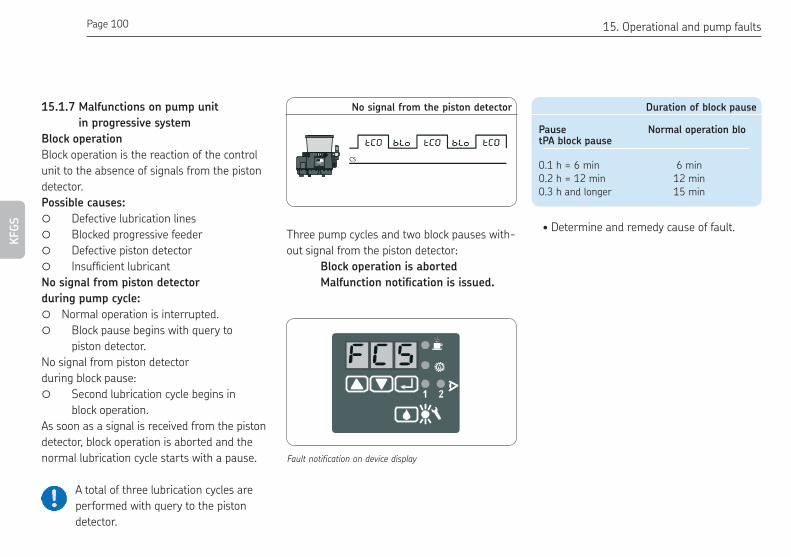
Page 100 EN
15.1.7 Malfunctions on pump unit
in progressive system
Block operation
Block operation is the reaction of the control
unit to the absence of signals from the piston
detector.
Possible causes:
Defective lubrication lines
Blocked progressive feeder
Defective piston detector
Insuficientlubricant No signal from piston detector
during pump cycle:
Normal operation is interrupted.
Block pause begins with query to
piston detector.
No signal from piston detector
during block pause:
Second lubrication cycle begins in
block operation.
As soon as a signal is received from the piston
detector, block operation is aborted and the
normal lubrication cycle starts with a pause.
A total of three lubrication cycles are
performed with query to the piston
detector.
No signal from the piston detector
CS
Three pump cycles and two block pauses with-
out signal from the piston detector:
Block operation is aborted
Malfunction notiication is issued.
Fault notification on device display
Duration of block pause
Pause Normal operation blo tPA block pause
0.1 h = 6 min 6 min 0.2 h = 12 min 12 min 0.3 h and longer 15 min
• Determine and remedy cause of fault.
15. Operational and pump faultsK
FG
S

Page 101 EN
KFG/KFGS pump malfunctions
Fault Category Possible cause Rectification
Pump Agitator in grease reservoir does not rotate during the activated pump cycle (CONTACT mode).
Malfunction Mechanical damage, e.g., motor defective
Electrical connection interrupted
• Replace pump - Loosen main line at outlet of pressure regulating valve. - Loosen electrical connection. - Loosen three fastening screws. - Remove defective pump. - Mount new pump and connect lubrication line
and electrical cable.• Perform commissioning and functional inspection.• Be sure the interval and contact times are correct. • Check or replace fuse. • Check electrical connections • Check cable set for damage.
Pump does not function when the
key is pressed, although all electrical connections are ok.
Malfunction Electrical control has failed. Pump drive/motor is defective.
Lubricant level in reservoir is below minimum.
Agitator does not rotate.
• Check fuse• Replace pump
• Fill lubricant reservoir to "max."
• Replace pump element Note: metering is indicated by grooves.
15.1.8 Malfunctions on KFG/KFGS pump units
15. Operational and pump faults
KFG
SK
FG

Page 102 EN
Continuation of "KFG/KFGS pump malfunctions" table
Fault Category Possible cause Rectification
Pump does not deliver any lubricant, although agitator is rotating.
Malfunction Suction problems due to air pockets in grease Pump element does not build up pressure, pump element is worn out. (This is indicated when the outlet can be closed with a finger once the main line is removed.)
Lubricant too stiff
• Dismantle pump element and operate pump using the key until grease discharges from outlet on housing.
• Replace pump element Note: metering is indicated by grooves.
• If necessary, adjust lubricant to work properly at lowest working temperature.
Pressure regulatingvalve on pump opens and lubricant discharges.
Malfunction System pressure is over 200/300 bar, e.g., due to feeder blockage or blocked lubrication point.
Valve is damaged or contaminated, so it does not close properly.
• Check system and repair/rework the system so the maximum system pressure at 20 °C is 200 bar.
• Replace pressure regulating valve .
15. Operational and pump faultsK
FG
SK
FG

Page 103 EN
15.2.6 Remedy faults
Alwayscheckcablesirstwhenafaultoccurs. Most signal cables are moni-
tored for breakage, so a defective cable
or loose contact can cause a fault
notiication.When a warning occurs, it is recom-
mended that the system be stopped
and the fault be remedied.
When a malfunction occurs, the fault
must be remedied immediately in order
to prevent damage to the machine and
the associated risk of accidents.
After the fault has been remedied and
before operation is resumed, the key
must be pressed or the equivalent CAN
command sent to reset the system's
faultstatusanddeletethefaultnotiica-
tions.
15.2.3 Fault types
Depending on the severity of the fault, the
control unit issues either a warning or a mal-
functionnotiication(seefollowingtable).15.2.4 Fault notiicationWarnings are indicated by a constant
LEDlight.Atthesametime,thefaultnotiica-
tion is stored in the FRAM.
Malfunctionsareindicatedbyalashing LED light. At the same time, the fault
notiicationisstoredintheFRAM.15.2.5 Read faults
Allfaultnotiicationsgeneratedduringop-
eration are stored in the control unit's FRAM
together with further system parameters and
a timestamp. They can then be read from the
FRAM. This allows each failure to be uniquely
identiiedbyitscode.Refertothe"LC-CAN5000-ConigurationandControlInter-face Protocol" manual for more information.
15.2 Operational malfunctions on KFGC
(CAN bus)
15.2.1 Pump malfunctions
The possible causes of malfunctions listed in
Chapter 11.1.8, "Malfunctions on KFG/KFGC
pump units," also apply for the KFGC CAN bus
version.
15.2.2 Faults detected by control unit
The comprehensive monitoring functions of
the LC-CAN 5000 control unit allow faults in
the operational process to be detected, regis-
tered and displayed.
Severalfaults,e.g.,duetoinsuficientilllevelortheabsenceofasignalfromthe piston detector, are only displayed
when system monitoring is active (see
Chapter 6.3.3.1, page 61).
15. Operational and pump faults
KFG
C

Page 104 EN
Fault types
Fault type Definition Display Example of fault Response by control unit
Warning
Malfunction
A problem has occurred that does not affect the operational sequence but can lead to an operational malfunction if not remedied.
A fault has occurred that affects the proper functioning of the lubrication system.
The lubrication points may not be supplied with adequate lubrication because a malfunction has affected the proper functioning of the lubrication system. Malfunctions must always be remedied immediately.
- LED lights up and remains constant
LED flashes
The fill level in the reservoir sinks to the level of the pre-warning sensor (only on systems equipped and configured with this functionality).
Insufficient number of piston detector signals from a lubrication zone during the pump cycle
The LED lights up. A fault notification is generated. Operation continues as normal.
1. Block operation up to configured number of repetitions
2. - If the piston detector signal has still not been received, the valve is closed and a fault notification is generated.
- The LED lights up.
- The remaining lubrication zones continue to operate normally.
15. Operational and pump faultsK
FG
C

Page 105 EN
KFGC (CAN bus) fault notifications
Fault Category Possible cause Rectification
Fill level warning
Warning Fill level in lubricant reservoir falls to warning sensor Break in sensor cable Lubricant too soft
• Immediately refill with lubricant (see Chapter 4.4, page 22), change pump element if necessary.
• Replace cable• Replace lubricant
Fill level fault Malfunction Fill level in lubricant reservoir reaches "min" mark Break in sensor cable
• Immediately refill with lubricant (see Chapter 4.4, page 22)• Replace the cable.
Cycle fault Malfunction Lubrication line defective Progressive feeder blocked or defective Piston detector defective Insufficient lubricant
Break in sensor cable
• Replace the defective line.• Clean the feeder or replace it.
• Replace the piston detector.• Immediately refill with lubricant (see Chapter 4.4, page 22),
change pump element if necessary.• Replace the cable.
Pressure build-up fault
Malfunction Lubrication line defective Pressure switch defective Pressure relief valve blocked or defective Insufficient lubricant
Break in sensor cable Lubricant too stiff Main line cross-section too small
• Replace the defective line.• Replace the pressure switch.• Clean the valve or replace it.• Immediately refill with lubricant (see Chapter 4.4, page 22),
change pump element if necessary.• Replace the cable.• Replace lubricant• Increase main line cross-section.
Pressure reduction fault
Malfunction Pressure relief valve blocked or defective Pressure switch defective Break in sensor cable Lubricant too consistent
• Clean the valve or replace it.• Replace the pressure switch.• Replace the cable.• Fill lubricant at suitable flow pressure, clean system.
15.2.7 Warning and malfunction indicator on KFGC (CAN bus) pump unit
15. Operational and pump faults
KFG
C

Page 106 EN
KFGC (CAN bus) fault notifications
Fault Category Possible cause Rectification
Short-circuit fault Malfunction Damaged cable or plug Incorrect installation• Replace the cable.• Check the electrical installation.
Temperature fault Malfunction Ambient temperature too high Output power too high• Check system for line blockage and lubricant for feedability.• Let pump unit cool down.
Motor current fault Malfunction Partial or total blockage of motor shaft and/or agitator
• Check the agitator for freedom of movement.• Check whether objects in the grease reservoir
are impeding the agitator.• Check the lubricant for feedability.
Open input/output Warning Input/output was configured but the component it was configured for is not connected
• Check the configuration.• Check whether all configured components are attached.
15. Operational and pump faultsK
FG
C

Page 107 EN
16. Technical data
Protective measures that must be taken for
operation according to the intended use in
machinery:
KFG; KFGS; KFGC (CAN bus)... 12/24 VDC:
"Functional Extra Low Voltage,"
"Protective Extra Low Voltage“ (PELV)
Disconnect the unit for insulation and
voltage inspection according to
EN 60204-1 1992.
16. Technical data
KFG
SK
FG
KFG
C
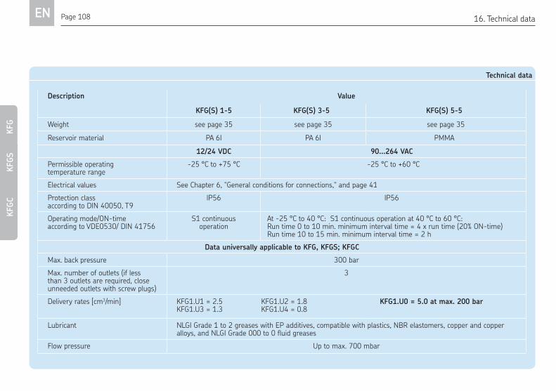
Page 108 EN
Technical data
Description Value
KFG(S) 1-5 KFG(S) 3-5 KFG(S) 5-5
Weight see page 35 see page 35 see page 35
Reservoir material PA 6I PA 6I PMMA
12/24 VDC 90...264 VAC
Permissible operating temperature range
-25 °C to +75 °C -25 °C to +60 °C
Electrical values See Chapter 6, "General conditions for connections," and page 41
Protection class according to DIN 40050, T9
IP56 IP56
Operating mode/ON-time according to VDE0530/ DIN 41756
S1 continuous operation
At -25 °C to 40 °C: S1 continuous operation at 40 °C to 60 °C: Run time 0 to 10 min. minimum interval time = 4 x run time (20% ON-time) Run time 10 to 15 min. minimum interval time = 2 h
Data universally applicable to KFG, KFGS; KFGC
Max. back pressure 300 bar
Max. number of outlets (if less than 3 outlets are required, close unneeded outlets with screw plugs)
3
Delivery rates [cm3/min] KFG1.U1 = 2.5 KFG1.U2 = 1.8 KFG1.U0 = 5.0 at max. 200 bar KFG1.U3 = 1.3 KFG1.U4 = 0.8
Lubricant NLGI Grade 1 to 2 greases with EP additives, compatible with plastics, NBR elastomers, copper and copper alloys, and NLGI Grade 000 to 0 fluid greases
Flow pressure Up to max. 700 mbar
16. Technical dataK
FG
SK
FG
KFG
C
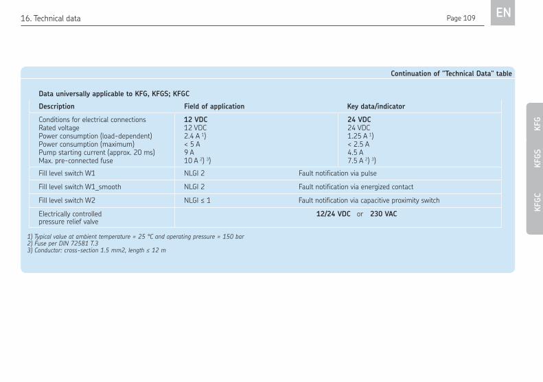
Page 109 EN
Continuation of "Technical Data" table
Data universally applicable to KFG, KFGS; KFGC
Description Field of application Key data/indicator
Conditions for electrical connections Rated voltage Power consumption (load-dependent) Power consumption (maximum) Pump starting current (approx. 20 ms) Max. pre-connected fuse
12 VDC12 VDC2.4 A 1) < 5 A9 A10 A 2) 3)
24 VDC24 VDC1.25 A 1) < 2.5 A 4.5 A7.5 A 2) 3)
Fill level switch W1 NLGI 2 Fault notification via pulse
Fill level switch W1_smooth NLGI 2 Fault notification via energized contact
Fill level switch W2 NLGI≤1FaultnotificationviacapacitiveproximityswitchElectrically controlled pressure relief valve
12/24 VDC or 230 VAC
1) Typical value at ambient temperature = 25 °C and operating pressure = 150 bar 2) Fuse per DIN 72581 T.3 3) Conductor: cross-section 1.5 mm2, length ≤ 12 m
16. Technical data
KFG
SK
FG
KFG
C
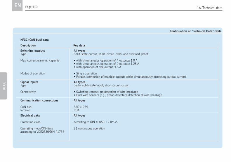
Page 110 EN
Continuation of "Technical Data" table
KFGC (CAN bus) data
Description Key data
Switching outputsType
Max. current-carrying capacity
Modes of operation
All types Solid-state output, short-circuit-proof and overload-proof
• with simultaneous operation of 4 outputs: 1.0 A • with simultaneous operation of 2 outputs: 1.25 A • with operation of one output: 1.5 A • Single operation • Parallel connection of multiple outputs while simultaneously increasing output current
Signal inputsType
Connectivity
All types digital solid-state input, short-circuit-proof
• Switching contact, no detection of wire breakage • Dual wire sensors (e.g., piston detector), detection of wire breakage
Communication connections
CAN busInfrared
All types
SAE J1939 IrDA
Electrical data
Protection class
Operating mode/ON-timeaccording to VDE0530/DIN 41756
All types
according to DIN 40050, T9 IP5k5
S1 continuous operation
16. Technical dataK
FG
C

Page 111 EN
17. Accessories
Accessories
Description Data Order No.
M12x1 circular connector, 4-pin, with cable for connecting to pis-ton detector and an external fault indicator
Cable set
Two-way distributor (for connecting to the M12x1 plug on the pump with 2x M12x1 outputs for piston detector and separate indicator lamp)
179-990-719
179-990-700
M12x1 plug without cable, with 4 pins, protection class IP 67 (mounted) 179-990-371
M12x1 angle plug without cable, with 4 pins, protection class IP 67 (mounted) 179-990-372
M12x1 plug, straight with 5 m cable, 4x 0.25 mm2, protection class IP 68 (mounted) 179-990-600
M12x1 angle plug with 5 m cable, 4x 0.25 mm2, protection class IP 68 (mounted) 179-990-601
Cable socket according to DIN 43 650
Type A (ISO 4400), pivoted, without LED, 1.5 mm2, line diameter 6 mm to 9 mm 179-990-034
Cable socket according to DIN 43 650
Type A (ISO 4400), pivoted, without LED, 1.5 mm2, line diameter 4.5 mm to 7 mm 179-990-034
Cable socket according to DIN 43 650
Type A (ISO 4400), pivoted, with red LED, 1.5 mm2, line diameter 6 mm to 9 mm 179-990-121
Additional data and electrical plug-in connections are available in brochure No. 1-1730,
"Electric Plug-and-Socket Connectors."
17. Accessories
KFG
SK
FG
KFG
C

Page 112 EN
BN
WH
BU
BK
BU
CS/PS
BN
X3
1
X2
2
3
4
+ SL2
1 2 3 4
1
2
3
4
X4
BU
BKSL22,4W
179-990-700
1
2
3
CS/PS
17.1 Connectivity for timer operation
with system monitoring, ill level control, piston detector and indicator
light
Connection for piston detector/pressure
switch CS
PIN Code Assignment
1 Voltage ( + ) 2 CS/PS Pressure/piston detector (signal) 3 ( - ) 4 CS/PS Pressure/piston detector (signal)
A double-pin plug with a special cable
adapter is required for this application.
Accessories
Description Data Order No.
M12x1 circular connector with cable for connecting to piston detector and an external fault indicator
Cable set
Two-way distributor (for connecting to the M12x1 plug on the pump with 2x M12x1 outputs for piston detector and separate indicator lamp)
179-990-719
179-990-700
Connection for fault notification SL2
PIN Code Assignment
1 2 3 SL2 “Fault” indicator light ( - ) 4 SL2 "Fault" indicator light ( + )
17. AccessoriesK
FG
S
AB
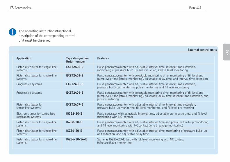
Page 113 EN
External control units
Application Type designationOrder number
Features
Piston distributor for single-line systems
EXZT2A02-E Pulse generator/counter with adjustable interval time, interval time extension, monitoring of pressure build-up and reduction, and fill level monitoring
Piston distributor for single-line systems
EXZT2A03-E Pulse generator/counter with selectable monitoring time, monitoring of fill level and pump cycle time (stroke monitoring), adjustable delay time, and interval time extension
Progressive systems EXZT2A05-E Pulse generator/counter with adjustable interval time, interval time extension, pressure build-up monitoring, pulse monitoring, and fill level monitoring
Progressive systems EXZT2A06-E Pulse generator/counter with selectable monitoring time, monitoring of fill level and pump cycle time (stroke monitoring), adjustable delay time, interval time extension, and pulse monitoring
Piston distributor for single-line systems
EXZT2A07-E Pulse generator/counter with adjustable interval time, interval time extension, pressure build-up monitoring, fill level monitoring, and fill level pre-warning
Electronic timer for centralized lubrication systems
IG351-10-E Pulse generator with adjustable interval time, adjustable pump cycle time, and fill level monitoring with NO-contact
Piston distributor for single-line systems
IGZ38-30-E Pulse generator/counter with adjustable interval time and pressure build-up monitoring, and fill level monitoring with NC contact (wire breakage monitoring)
Piston distributor for single-line systems
IGZ36-20-E Pulse generator/counter with adjustable interval time, monitoring of pressure build-up and reduction, and adjustable delay time
Piston distributor for single-line systems
IGZ36-20-S6-E Same as IGZ36-20-E, but with full level monitoring with NC contact (wire breakage monitoring)
The operating instructions/functional
description of the corresponding control
unit must be observed.
17. Accessories
KFG

Page 114 EN
External control units
Application Type designationOrder number
Features
Progressive systems IGZ51-20-E Pulse generator/counter with selectable intermittent or continuous pump operation, with adjustable stroke rate, selectable interval time and monitoring time, and monitoring of fill level and pump cycle time
Progressive systems IGZ51-20-S2-E Same as IGT51-20, but with non-volatile memory in case of power failure
Piston distributor for single-line systems
IGZ51-20-S3-E Pulse generator/counter with adjustable interval time, interval time extension, monitoring of pressure build-up and reduction, adjustable delay time and connectable non-volatile memory in case of power failure
Progressive systems IGZ51-20-S7-E Same as IGZ51-20-S2, but with fill level switch as NC contact, pump cycle time = set monitoring time
Progressive systems IGZ51-20-S8-E Pulse generator/counter with selectable intermittent or continuous pump operation, pre-lubrication, selectable interval time and monitoring time, monitoring of fill level, pump cycle time and pulses, and non-volatile memory in case of power failure
17. AccessoriesK
FG

951-170-203-EN
SKF Lubrication Systems Germany GmbH 2. Industriestrasse 4 ·68766 Hockenheim · Germany Tel. +49 (0)62 05 27-0 · Fax +49 (0)62 05 27-101 www.skf.com/lubrication
SKF Lubrication Systems Germany GmbH Motzener Strasse 35/37 ·12277 Berlin · Germany PO Box 970444 · 12704 Berlin · Germany Tel. +49 (0)30 72002-0 · Fax +49 (0)30 72002-111 www.skf.com/lubrication
The contents of this publication are the copyright of the publisher and may not be repro-
duced in whole or in part without permission of SKF Lubrication Systems Germany
GmbH. Every care has been taken to ensure the accuracy of the information contained in
this publication. However, no liability can be accepted for any loss or damage, whether di-
rect, indirect or consequential arising out of use of the information contained herein.
All SKF products may be used only for their intended purpose as described in these as-
sembly instructions with associated operating instructions. If assembly/operating instruc-
tions are supplied together with the products, they must be read and followed. Not all lu-
bricants can be fed using centralized lubrication systems. SKF can, on request, inspect
the feedability of the lubricant selected by the user in centralized lubrication systems.
Lubrication systems and their components manufactured by SKF are not approved for
use in conjunction with gases, liquefied gases, pressurized gases in solution, vapors or
such fluids whose vapor pressure exceeds normal atmospheric pressure (1013 mbar) by
more than 0.5 bar at their maximum permissible temperature.
Particular attention is called to the fact that hazardous materials of any kind, especially
the materials classified as hazardous by CLP Regulation EC 1272/2008 may only be used
to fill SKF centralized lubrication systems and components and delivered and/or distrib-
uted with the same after consulting with and receiving written approval from SKF.