kht121mc eng 140513 - vallox oy · 3561 models vallox 121 mc r vallox 121 mc l operating,...
TRANSCRIPT
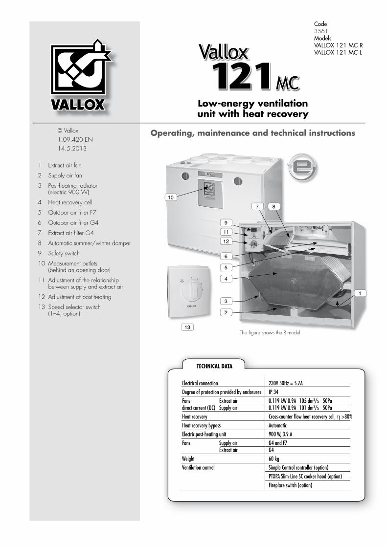
Low-energy ventilation unit with heat recovery
© Vallox1.09.420 EN14.5.2013
Vallox121MC
1 Extract air fan
2 Supply air fan
3 Post-heating radiator (electric 900 W)
4 Heat recovery cell
5 Outdoor air fi lter F7
6 Outdoor air fi lter G4
7 Extract air fi lter G4
8 Automatic summer/winter damper
9 Safety switch
10 Measurement outlets (behind an opening door)
11 Adjustment of the relationship between supply and extract air
12 Adjustment of post-heating
13 Speed selector switch (1–4, option)
13
Code 3561ModelsVALLOX 121 MC RVALLOX 121 MC L
Operating, maintenance and technical instructions
10
1
2
3
4
5
6
11
12
87
9
Electrical connection 230V 50Hz = 5.7A
Degree of protection provided by enclosures IP 34
Fans Extract air 0.119 kW 0.9A 105 dm³/s 50Padirect current (DC) Supply air 0.119 kW 0.9A 101 dm³/s 50Pa
Heat recovery Cross-counter fl ow heat recovery cell, η >80%
Heat recovery bypass Automatic
Electric post-heating unit 900 W, 3.9 A
Fans Supply air G4 and F7 Extract air G4
Weight 60 kg
Ventilation control Simple Control controller (option)
PTXPA Slim-Line SC cooker hood (option)
Fireplace switch (option)
TECHNICAL DATA
The fi gure shows the R model

2
Vallox121MC
© VALLOX • We reserve the right to make changes without prior notice.What the units include can vary depending on the sales area.
Adjustment of supply air temperature and summer/winter functionThe temperature of air coming to the dwelling can be adjusted between circa +10 °C and +30 °C. The midpoint of the adjustment range is circa +20 °C. When supply air temperature adjustment has been turned in the OFF position, post-heating is not active. This means that summer function is activated for the ventilation unit. The unit has a motorised summer/winter function. When the summer function is on, the heat recovery cell is bypassed as soon as outdoor air temperature has risen above +14 °C. When outdoor air temperature goes below +12 °C, the unit starts to recover heat. When supply air temperature adjustment is in the AUTO position, automatic function is activated for the unit. In this case, the setpoint for post-heating is +17 °C and the heat recovery cell is bypassed automatically according to outdoor temperatures as indicated above. When the unit bypasses the heat recovery cell, in which case summer function is activated, post-heating is off.
Fireplace switch functionIt is possible to connect a timer-operated switch to the unit. The switch stops the extract air fan during the time when the fi replace is heated. NOTE! The starting of the extract air fan may weaken draught in the fi replace! In winter, this situation may disturb the winter function of the unit. The situation will normalise in a while, after the fi replace function stops.
Winter function of ventilation unitA threshold value has been set at the factory for the freezing of the heat recovery cell. When the threshold is exceeded, the ventilation unit starts to melt the heat recovery cell. Melting is done by stopping the supply air fan.A normal melting period takes from 15 to 45 minutes depending on the extent of ice on the heat recovery cell and on the amount of extract air fl ow.The unit has two different choices for the winter function. One choice is meant for very wet conditions (for instance swimming hall) and the other for normal operation in dwellings and detached houses.The factory setting is normal winter function for dwellings and detached houses.
Adjustment of the relationship between supply and extract air This feature may be useful when adjusting air fl ows at the valves during mounting. After the valves have been adjusted, a user does not need, and must not, touch the adjustment. When needed, supply or extract air fl ow can be reduced at the potentiometer. When the potentiometer is approximately halfway, supply and extract air fl ow have not been reduced. Turning the potentiometer anticlockwise reduces the air fl ow on the supply side, and turning it clockwise reduces the air fl ow on the extract side.
Maintenance reminderThe unit reminds of the need for maintenance every six months if an indicator (not standard) has been connected to the connectors of the fault signal relay. The indicator then blinks at one-second intervals. The maintenance reminder is reset when the door of the ventilation unit is opened. See the maintenance instructions for information on the necessary maintenance activities.
Fan speed adjustmentThe fan speed of Vallox ventilation unit can be controlled with a control switch (option), with a separate cooker hood (option) or directly with a 0-10 V voltage signal.Speeds 1, 2, 3 and 4 can be selected at the control switch:1. Operation during absence. When the dwelling is empty, ventilation can be reduced
temporarily.2–3. Normal operation. In normal operation, air has to be replaced once every two hours.4. Boosted operation. Cooking, taking a sauna bath, washing, drying clothes, using the
toilet, having guests or a corresponding situation may cause a need for higher ventila-tion than in normal operation.
OPERATING INSTRUCTIONS
Four-step control switch(option)
Cooker hood PTXPA-SC(option)Cooker hood PTXPA-SC
Adjustment of supply air temperature
Supply and extract air fl ow adjustment potentiometer
Fireplace switch, fl ush mounting (option)
2
This appliance can be used by children aged from 8 years and above and persons with reduced physical, sensory or mental capabilities or lack of experience and knowledge if they have been given supervision or instruction concerning use of the appliance in a safe way and understand the hazards involved.
Children shall not play with the appliance.
Cleaning and user maintenance shall not be made by children without supervision.

3
Vallox121MC
© VALLOX • We reserve the right to make changes without prior notice.What the units include can vary depending on the sales area.
Led blinks Problem Repair
1 Supply air sensor after the HR cell is faulty
Check the sensor and conductors, replace if needed
2 Extract air sensor is faulty Check the sensor and conductors, replace if needed
3 Supply air sensor is faulty Check the sensor and conductors, replace if needed
4 Exhaust air sensor is faulty Check the sensor and conductors, replace if needed
5 Outdoor air sensor is faulty Check the sensor and conductors, replace if needed
6 Supply air fan has stopped Check the wiring of the fan, replace the fan if needed
7 Extract air fan has stopped Check the wiring of the fan, replace the fan if needed
8 EEPROM faulty Replace the circuit board of the unit with a new one
TroubleshootingWhen a fault described in the table appears, the unit indicates of the fault with a fault signal relay, indicator light and LED on the circuit board. The number of blinks reveals the fault in question
OPERATING INSTRUCTIONS
MAINTENANCEBefore starting maintenance operationsDisconnect the plug of the VALLOX 121 MC unit before starting maintenance operations. When you open the VALLOX 121 MC unit, the security switch (S) turns voltage off. In spite of this, disconnect the plug of the unit.
When the maintenance reminder gives an alarm, the cleanliness of the fans must be checked. Outdoor air is filtered in the unit with two kinds of filters. A coarse filter (A) filters off insects, heavy pollen and other dust. An F7 class fine filter (B) filters off fine dust invisible to the eye. Extract air is filtered with a coarse filter (C).By using original Vallox filters you ensure good operation of the ventilation unit and the best filtering result. The replacement interval of filters depends on dust content in ambient air. It is recommended to replace fans in spring and autumn, but at least once a year.
Heat recovery cellCheck the cleanliness of the heat recovery cell D at one-year intervals. NOTE! The laminas of the cell are very thin and get easily damaged. The correct way of removing the cell is to put your hands behind the cell and slowly pull it off. If the cell is dirty, soak it in a solution of water and washing-up liquid. Rinse the cell clean with a jet of water. When all the water has drained from between the laminas, the cell can be remounted to the unit. Before mounting check the seals. Check that the seal does not start “rolling” with the cell when you push the cell in place.
AC
B
D
SFans
Check the cleanliness of the fans when carrying out maintenance for a filter and the heat recovery cell. Clean the fans if needed. The fans can be removed from the unit for cleaning. The fan blades can be cleaned with compressed air or with a brush. Do not remove or move the balancing pieces on the fan blade.
Removing supply fan (T)Before removing the supply fan, remove the HR cell (D) by pulling carefully. Place a thin sheet board or paper under the fan in order to prevent the bottom tank from being scratched when removing the fan. Unfasten the fixing screw of the fan (H, hex socket-head cap screw AV 4 mm) and place the fan on the bottom tank. Rotate the fan (model R anticlockwise, model L clockwise) and slide the fan along the bottom tank. Unfasten the quick couplings of the fan wires and lift the fan off. Check that the collar rubber is in place before mounting the fan back in place.
Removing extract air fan (P)Before removing the extract air fan take out the coarse filter (C), fine filter (B) and HR cell (D) by carefully pulling them and remove the maintenance door (F), fixed with two screws. Place a thin sheet board or paper under the fan in order to prevent the bottom tank from being scratched when removing the fan. Unfasten the fixing screw of the fan (H, hex socket-head cap screw AV 4 mm) and place the fan on the bottom tank. Rotate the fan (model R clockwise, model L anticlockwise) and slide the fan along the bottom tank. Unfasten the quick couplings of the fan wires and lift the fan off. Check that the collar rubber is in place before mounting the fan back in place.
Filters
4
Vallox121MC
© VALLOX • We reserve the right to make changes without prior notice.What the units include can vary depending on the sales area.
70
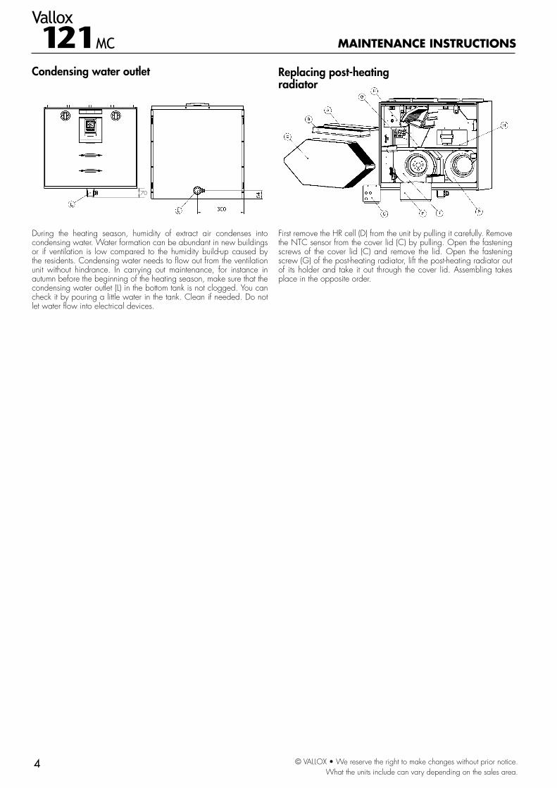
During the heating season, humidity of extract air condenses into condensing water. Water formation can be abundant in new buildings or if ventilation is low compared to the humidity build-up caused by the residents. Condensing water needs to flow out from the ventilation unit without hindrance. In carrying out maintenance, for instance in autumn before the beginning of the heating season, make sure that the condensing water outlet (L) in the bottom tank is not clogged. You can check it by pouring a little water in the tank. Clean if needed. Do not let water flow into electrical devices.
First remove the HR cell (D) from the unit by pulling it carefully. Remove the NTC sensor from the cover lid (C) by pulling. Open the fastening screws of the cover lid (C) and remove the lid. Open the fastening screw (G) of the post-heating radiator, lift the post-heating radiator out of its holder and take it out through the cover lid. Assembling takes place in the opposite order.
Condensing water outlet
MAINTENANCE INSTRUCTIONS
Replacing post-heating radiator

5
Vallox121MC
© VALLOX • We reserve the right to make changes without prior notice.What the units include can vary depending on the sales area.
Dimensions and duct outlets
Duct outletsInner diameter of female outlet collar1. Supply air to the dwelling2. Extract air from the dwelling
to the unit3. Outdoor air to the unit4. Exhaust air out
Measuring pointsMeasuring points after the connection outlet.Fan curves indicate the total pressure available for duct losses.
Input powers of fans
Fan control voltage
(V)
Extract air flow (l/s)
Combined input power
of fans W
4 25 18
5 36 27
6 45 37
7 56 56
8 70 81
9 83 116
10 93 159
11.2 104 215
Supply/extract air flows
Sound values
P = Extract air fan T = Supply air fan
Input power (total) (W) Air flow (max) (dm3/s)
SFP =SFP (Specific Fan Power) recommended value <2.5 (kW m3/s)At a lower total pressure, SFP will be smaller at the same speed
Sound power level in supply air duct (one duct) by octave band LW, dB
Sound power level in extract air duct (one duct) by octave band LW, dB
ADJUSTMENT POSITION/AIR FLOW dm3/s ADJUSTMENT POSITION/AIR FLOW dm3/sAdjustment position 4.0 5.0 6.0 7.0 8.0 9.0 10.0 11.2 4.0 5.0 6.0 7.0 8.0 9.0 10.0 11.2
Air flow dm3/s 17.2 29.4 39.8 51.1 65.6 73.1 78.9 91.6 25.2 35.5 44.9 56.3 61.9 75.6 82.6 94.5
Medium frequen-cy of the octave band Hz
63 63 72 73 77 80 83 84 87 51 54 57 60 64 64 68 71
125 53 59 63 66 69 73 75 79 44 48 51 55 59 62 64 67
250 45 50 53 57 62 65 68 70 38 41 43 49 53 56 58 60
500 40 45 47 51 55 58 61 63 26 32 34 38 42 45 48 50
1000 39 46 49 54 57 59 60 62 22 27 30 34 37 39 42 43
2000 32 40 45 51 55 58 61 64 * 18 22 27 31 34 36 39
4000 18 29 35 41 46 50 52 55 * * * 14 19 24 27 29
8000 * * 22 31 38 42 45 49 * * * * * * * *
LW,dB LWA, dB(A)
63 72 73 78 80 83 85 88 52 55 58 61 65 67 70 73
44 51 55 59 63 65 68 70 32 36 39 44 47 50 53 55
Sound pressure level coming from the unit through the envelope in the rooms where the unit has been installed
(10m2 sound absorption) Vallox 121 MC ADJUSTMENT POSITION/AIR FLOW dm3/s
4.0 5.0 6.0 7.0 8.0 9.0 10.0 11.224/26 33/34 40/42 50/51 62/62 71/71 82/82 92/92
LpA, dB (A) 26 30 32 35 40 42 45 47
Pressu
re los
s in d
ucts.
Total
pres
sure
TECHNICAL DATA
70 m
m ins
talla
tion
spac
e
Model: L
Model: R
The figure shows the R model
Extract airSupply air
ES
Recommended operating range
Volume flow rate

6
Vallox121MC
© VALLOX • We reserve the right to make changes without prior notice.What the units include can vary depending on the sales area.
123456789
1
2
3
4
5
LINENEUTRALSLISNISLOSNOSFLSFNEFLEFNFSOFSIAHLAHNPHLPHN
230V 50Hz
BL1BL
BNE/IE/O
1 2 3 4
LED
90°C130°C
R1
T1 T2
7022800
M
1 2 3 4
LED-+S
LINE: Phase voltageNEUTRAL: Zero voltageSLI: Phase voltage to safety switchSNI: Zero voltage to safety switchSLO: Phase voltage to circuit board from safety switchSNO: Zero voltage to circuit board from safety switchSNO: Phase voltage to supply air fanSFN: Zero voltage to supply air fanEFL: Phase voltage to extract air fanEFN: Zero voltage to extract air fanFSO: Input to fireplace switchFSI: Fireplace switch outputAHL: Phase voltage to post-heatingAHN: Zero voltage to post-heatingPHL: Phase voltage to additional heaterPHN: Zero voltage to additional heaterBL: Damper motor phase ABL1: Damper motor phase BBN Zero voltage to damper motorE/I: Input voltage to fault signal relayE/O: Fault signal relay output
DIP switch Up Down
1. Post-heating Electric VKL
2. Additional heating Electric MLV
3. Unit type Bypass Input fan stopped
4. Winter function Normal Wet
Electrical diagram
TECHNICAL DATA
Supply air fan
Post-heating electric radiator 900W
Fireplace switch
Belimo damper motor 230 VAC
Protective ground to a separate block
Extract air NTC
Outdoor air NTC
Supply air to the dwelling NTC
Exhaust air NTC
Supply air from the cell NTC
Adjustment of freezing level
9. GND / -8.7.6. GND / -5.4.3. GND / -2. 11.2 VDC / +1.
FAULT SIGNAL
Adjustment of post-heating DIP switch
PWM level adjustment
Programming connector
An external 0–10 Vdc voltage input can be introduced between control signal S and GND signal for fan control.
External controller or cooker hood
Safety/door switch
Extract air fan

7
Vallox121MC
© VALLOX • We reserve the right to make changes without prior notice.What the units include can vary depending on the sales area.
MountingVALLOX 121 MC is mounted on the wall with a mounting plate as shown in the adjacent figure.
Wall mountingMount VALLOX 121 MC in a place where temperature does not go below +10 °C. Without protective enclosure, the unit must be located in a place with no acoustic disturbance, such as storerooms or technical rooms. VALLOX 121 MC can also be located in a damp room, but not in a bathroom next to a sauna bath.
Wall constructionThe weight of the unit (60 kg) has to be taken into account when mounting the wall bracket on the wall structure. Avoid mounting the unit on a hollow, echoing dividing wall and on a bedroom wall because of sound conduction, or prevent sound conduction.
Electrical connectionsThe unit has a plug connection. The connection box of the unit is located loosely upon the unit and can be moved to another place as desired.
Duct connections of unit The unit is equipped with six Ø 125-mm collars. Necessary connecting pieces (such as inner or bent connector) can be attached to the collar. NOTE! The connecting head of the connecting piece must not be inserted into the collar by more than 30 mm. Fix the ducts steadily and tightly to the relevant outlets. (Note! Unit models L/R). Implement duct insulation if needed as defined in the ventilation plan.
162
12 21
20 60
20 30 30
2060 11
203030
11
84 84
35 30 35
ø7 550
30
25 25
30°
Wall mounting plate
Air flow measurement outletsThe fixed air flow measurement outlets of the unit are located in the door below the latch. You can measure the total pressure of the supply and extract air ductwork at the measurement outlets, using a differential pressure instrument. Pressure readings and air volume tables (see Page 5) show volume flow rates at various adjustment positions. The red measurement hoses are intended for measuring the supply air ductwork and the black measurement hoses for measuring the extract air ductwork.
Condensing water connectionsThe delivery includes a Silent Kick water seal. By connecting a pipe to the water seal the water condensing from extract air can be led to a floor drain (not directly to the drain). Silent Klick water seal prevents the sound caused by water as the water seal dries up. The pipe must not rise after the water seal. The condensation water discharge outlet is located at the rear edge in the middle of the unit. Because of this the unit has to be mounted horizontally level.
MOUNTING INSTRUCTIONS
During mounting, the unit rises 10 mm higher than the final height.
Bottom edge of wall bracket
Room required by VALLOX Silent Klick water seal.
Bottom edge of wall bracket
14 pcs
Wall mounting plate

Vallox121MC
© VALLOX • We reserve the right to make changes without prior notice.What the units include can vary depending on the sales area.
1.09
.420
F/14
.5.2
013/