kicker and proton beam for ucn - paul scherrer...
TRANSCRIPT

Kicker and Proton beam for UCN
Collection of eight reports or
memos written during the years 2000 to 2005.
(Some details may not be true anymore but is showing
some historic development of the topics)
by Urs Rohrer, beam line physicist
PSI Accelerator Division
Department of Large Research Facilities

Chapter of UCN-Report from 23. Nov. 2000 13. The Proton beam to the UCN facility at PSI. The UCN facility in its final design requires the full-intensity proton beam at the spallation target for about 3 seconds duration every 10 minutes. For this reason 2 important considerations are relevant:
1. The side effects to other experiments (SINQ, myon/pion beams, gantry). 2. Investments and time schedule for modifications of the proton beam line.
The proton beam from the PSI 590 MeV cyclotron can be diverted to the future UCN facility in 3 ways:
1. Splitter mode: A small portion (≤ 20 µA) of the proton beam can be pealed off in DC-mode with the help of an electrostatic septum (splitter) which is located about 10 m after the extraction from the cyclotron.
2. Direct DC beam (single user) mode: The whole beam is diverted into the beam line to the UCN facility by means of the 2 small compensation dipole magnets belonging to the DC splitter (SHC4x). Because of the week shielding of this beam line only about 20 µA can be run permanently in this mode.
3. A new pulsed beam mode: With the help of a fast kicker the whole beam (≈2 mA) may be diverted for up to 3 seconds every 10 minutes onto the UCN spallation target. In this mode the average intensity will be about 10 µA. So the shielding does not have to be improved.
In a first stage we intend to do some UCN production tests with proton beam intensities of up to 20 µA. This means it will be done either with mode 1 or 2 (mode 2 only in rare cases), which is faster, easier and cheaper to realize. In a second stage the kicker magnet will be put in place, which allows it to divert the full intensity proton beam (2 mA) for about 3 seconds every 10 minutes onto the UCN target. Because of proton beam loss considerations, the only position of such a kicker magnet is just in front of the DC-splitter (EHT4). The original and the modified layout of the proton beam line between the dipole magnet AHC and the splitter (EHT4) is shown in Fig. 13.1. The needed space for the magnetic kicker will be created by shifting the quadrupole lens QHA4 and the monitor box MHP5/6 some 40 cm towards QHA3. To compensate for this gain, the vacuum pump PH11 and the vacuum valve VHD1 have to be replaced by some new models, which require less space. The vacuum chamber of the kicker consists of ceramics in order to avoid eddy currents and the yoke is made out of ferrite in order to fulfil the requirements of a short rise time of less than 1 ms. The big advantage of the fast kicker method is the fact that it does not interfere with the rather complicated acceleration process and hardly diminishes the beam quality for other simultaneous users. The steering effects of the 2 splitter-compensation magnets (SHC4x) used for making direct DC-beam towards UCN and the proposed kicker magnet are compared in Fig. 13.2. Both magnets produce an angular deviation of 6 mrad and a horizontal displacement of about 40 mm at the position of the magnetic septum ABS, which is necessary to deflect the beam into the beam line to the UCN target. The complete proton beam envelopes between the cyclotron exit septum AHA and the UCN target are shown in Fig. 13.3. Because of loss considerations the average diameter of the 2 mA proton beam along the beam line is kept relatively narrow (4σ < 20 mm). But at the location of the UCN spallation target thermal conditions require a 4σ-beam diameter of at least 110 mm. This is achieved by means of the single quadrupole lens QBB7: In x-direction the beam is over-focussed and in y-direction de-focussed in order to blow up the beam to the required diameter. Because the

centering of the 2 mA beam in direction of the UCN target cannot be tested in DC mode, it is necessary to be able to send short beam pulses (<5ms) in this direction in order to avoid interlocks. During this short time the position of the beam has to be detected with beam position monitors (BPMs) at a rate of 1 kHz. The existing BPMs are designed for 20 µA, and are not capable of detecting short high-intensity pulses. So they have to be replaced by devices of new design. A sketch of the layout of the proton beam line between the last bending magnet ABK2 and the UCN target is shown in Fig.13.4. Because of the required large size of the beam at the location of the target the beam tube diameter in front of it has to have an inner diameter of 200 mm. In order to be capable to measure or verify the diameter of the pulsed beam, 2 pairs of newly engineered harp monitors and a halo monitor have been included in the design. Because of the expected radiation levels (mainly due to backscattering from the target and possible beam spills from beam in direction to the Pirex target) all components have been embedded in layers of specially shaped concrete blocks. (The drawn shielding blocks in Fig. 13.4 are only a regular pattern and do not represent the reality.) The last section (beam tube 3) is placed between 2 cushion gaskets and designed to be removable together with the local shielding around it in order to make space for a shielded box for an eventual replacement of the UCN spallation target. Table 1: Fiscal and manpower needs for the proton beam line:
Activity Responsible Money (ksfr) Manpower (MM) only
for 2 mA
Mechanical: channel-shutter H. Obermeier 30 2
Mechanical: 3 vacuum-chambers with supports for alignment. H. Obermeier 60 5
Mechanical: 3 Diagnostics Plug-in units (2 harps, 1 Halo-monitor) H. Obermeier 60 10
Mechanical: 3 Ionisation-monitors H. Obermeier 20 2
Mechanical: Modification of p-channel for kicker magnet in front of EHT D. Suhi ? 10 3 *
Vacuum: 2 HV-pump-units with valves, fore-pumps and control units R. Knecht 80 1
Vacuum: 2 Cushion-Gaskets with fore-pump for intermediate vacuum R. Knecht 30 2
Vacuum: Bellows, tubes, gaskets etc R. Knecht 15 1 Vacuum: New pump and valve in front of kicker magnet R. Knecht 40 1 *
Shielding (special concrete blocks) M. Baumann 30 3 Kicker Magnet (ferrite) D. George 20 3 * Kicker Power-Supply F. Jenny 25 10 * Control System (Interlock, Kombis) I. Jirousek 38 7 Control System (Kicker Magnet) I. Jirousek 12 3 * Diagnostic-Electronics (Harps, MBIs) L.Rezzonico 15 15
Diagnostic-Electronics for BPMs L.Rezzonico 20 12 *
Diagnostics: 7 new BPM-Monitor pairs with new boxes and bellows L.Rezzonico 80 5 *
Power-Supplies for QBB7 & ABK2 M. Horvath 1 2 Hallen-Dienst A. Kuhn 10 6 Cabeling H.R. Meier 40 12 Cooling/Compressed Air A. Weber 10 1 PSA (1st stage) S. Staudenmann 40 3 PSA (2nd stage) S. Staudenmann 40 6 *
Total 726 115

Fig 13.1: Proposed layout of the proton beam line for pulsing with a fast kicker magnet. AHC: dipole magnet; QHA3/4: quadrupole lenses, PH11: vacuum pump; VHD1: vacuum valve; MHP5/6: beam monitors; EHT4: electrostatic beam splitter; SHC4x: dipole steering magnets; kicker: new fast deflecting dipole magnet. The upper half of the picture shows the present situation without the kicker. The lower portion of the picture shows it after the modifications for having the fast kicker magnet in place.

Fig.13.2: The 6 mrad deflection trajectories of the proton beam with the dipole magnets SHC4x and the future fast kicker magnet for guiding the proton beam to the UCN target. Both produce the required displacement of 40 mm at the entrance of the magnetic septum ABS.
Fig. 13.3: The estimated 2 mA proton beam envelopes between the extraction septum AHA of the 590 MeV proton accelerator and the UCN target. The relatively narrow beam is blown up in both directions by the single quadrupole lens QBB7.

Fig. 13.4: Layout of the new proton beam line between the last bending magnet and the UCN target. ABK2: bending magnet; QBB7: quadrupole lens; VBD3: vacuum valve; PB3: vacuum pump; KBV2: channel shutter; MBH1x/2y,MBH3x/4y: harp monitors; MBB1o/u/l/r: halo monitor; KD1/2/3: vacuum cushion gaskets.

Report from April-11-2001
Proposal for an early demonstration of the functioning of a fast kicker magnet for the 590 MeV proton beam to the UCN target.
M. Daum, D. George, F. Jenni, I. Jirousek, K. Kirch, A.C. Mezger,
U. Rohrer and P.A. Schmelzbach 1. Introduction. The UCN facility in its final design requires the full-intensity proton beam at its spallation target for about 3 seconds duration every 10 minutes. The only reasonable method to achieve this goal without too much disturbing the other users of the PSI 590 MeV proton beam is with the help of a fast kicker magnet. With this new device the whole beam may be diverted within a switching time of about 1 ms from the targets M and E towards the UCN target and after an on-time of up to 3 seconds again back onto the targets M and E in about 1 ms. The reviewers of the ‘Technical Review of the UCN Source Project Proposal at PSI” on Nov. 14 and 15, 2000 were concerned about the activation and reduction of life time of the magnetic deflection septum (ABS) with the proposed rise and fall time of 1 ms and felt it would be desirable to have PSI performing an early demonstration of the functioning of the beam switching with the fast kicking process before embarking on the overall construction effort for the whole facility. For doing so, we need some beam development time to test a new idea for suppressing the beam losses during the switching process (see below in chapter 3) and we need a kicker magnet mounted at the proper location in the proton beam line together with the appropriate power supply being able to deliver the fast rising or falling current. 2. Positioning the kicker magnet. Fig 1 shows the place where the kicker magnet has to be placed. This device will be mounted just in front of the DC-splitter (EHT4). Unfortunately, with the present layout there is no space to put the kicker right there. It is necessary to have it as close to the EHT4 as possible in order to keep the displacement of the beam - and therefore the losses produced by it at the EHT4 exit - as low as possible (see Fig 2). The space requirements for the kicker are about 40 cm in beam direction. Therefore, the profile monitor-box MHP5/6 and the quadrupole QHA4 have to be moved towards the cyclotron by this amount. In order to gain this space somewhere, the vacuum pump PH11 and the valve VHD1 have to be replaced by less space-consuming modern devices (see Fig 1). We strongly recommend that these modifications for gaining the needed 40 cm of space just in front of the DC-splitter (including the ceramics vacuum tube and the cabling for the kicker) will be implemented already during the next shutdown (in early 2002, because the optical influence of such a modification is minimal and therefore does not affect the quality of the beam towards the targets M and E and to the SINQ.). In case the kicker and the power supply are not ready for being built in during this next shutdown, this may be done later during one of the following monthly 2-day service periods (no breaking of the EHT4 vacuum needed) during the year 2002. 3. Method to reduce the beam losses during the kicking process. In order to reduce the beam losses near and at the ABS and to be able to increase the switching frequency for diagnostics purposes, we propose to suppress - in a synchronised manner - the beam at least during the steep part of the switching process of the fast kicker. This can be done with the

interlock kicker (AVKI) in the dome of the Cockroft-Walton pre-injector by turning off the beam for about 1 to 10 ms. One direction, namely the fast switching off of the beam has already been well tested with thousands of interlocks, but the immediate turning on of the beam after 1 to 10 ms has never been tried so far. Possible reasons why this may not work are the load depending behaviour of the high voltage of the pre-injector, the HF of the resonators of the injector-2 or of the cavities of the ring-cyclotron. Therefore, we ask for some beam development time during the HE-beam period starting in May of this year in order to investigate this fast suppression process of the proton beam. This may already be done without having the kicker in place and without having the power supply already being developed. We just need some beam onto the targets M and E and the beam dump. Additionally, an electronic device (similar to a pulser) is required, which allows in parallel to the machine interlock to control the AVKI power supply input. If it turns out, that the suppression works, then the rise and fall time of the kicker magnet power supply (T2-T1 ≈ 1 ms, see Fig 7) could be made even longer (up to 10 ms according to the outcome of the AVKI suppression tests) without causing any problems for dealing with some excessive beam losses at the collimator in front of the septum magnet ABS. The sum of the average beam losses caused by the DC beam splitter (EHT4) is about 0.15 %, but with virtually no losses at the ABS collimator. With the kicker magnet, the sum of the beam losses with 3 kicks (two for diagnostic purposes, see Fig. 8) per 10 minutes and no beam suppression with the interlock kicker (AVKI) and a transition time of 1 ms would sum up only to 10 ppm. About half of it (5 W average thermal power with 2 mA beam intensity) would be concentrated on the radiation-cooled ABS collimator, which will be hit frontally with a relatively small beam spot (σx = 2 mm, σy = 3 mm). Installing a new water-cooled collimator is not necessary, because the surface of the plate-shaped collimator (750 cm²) is sufficiently large to keep it cool (∆T = 15° C for 5 W thermal power). The activation of the collimator will remain relatively low, because long living isotopes do not have a chance to build up considerably, because the summed-up time intervals with beam hitting the collimator is only about 100 seconds per year (with 1 ms switching time). The insulation of the coils of the septum magnet is non-organic (radiation hard) and may not be damaged by the produced neutrons. 4. The requirements for the fast kicker power supply. When it comes to the decision about the timing requirements for the switching power supply, one has to understand what happens with the beam during the transition time for building up the 6 mrad angular displacement and after some variable amount of time the reversal to zero. Fig. 4 shows the offsets of the central beam trajectories for 95, 96, 97, 98 and 99 % of the full displacement amplitude of 6 mrad for the proton beam to the proposed UCN target. From this figure, one can see that only near the UCN target values exceeding 2 % could cause excessive losses along the beam tube. If the time is less than 5 ms, no harm will be done to the components and the machine interlock system will not react during this short interval. Fig. 5 shows the same for the proton beam to the targets M and E and to the beam dump. Only after target E, the amplitudes for displacements above 2 % are big enough to eventually cause an interlock if these displacements last longer than about 5 ms. The main obstacle in the way of the sweeping beam is the collimator in front of the magnetic septum ABS (see Fig. 6). The separation of the two beam positions for 6 mrad is around 41 mm. This value may be deduced from the 1-mrad-displacement trajectory shown in Fig. 2. The shown horizontal beam size (4σ = 8 mm) at this location may be extracted from the fraction of measured beam envelopes shown in Fig 3. About half of the angular path of 6 mrad is leading over this collimator. Therefore, the time between 15 % and 85 % of the kicker amplitude in both ways should be as short as reasonably possible (This is only of importance, if the beam suppression with the interlock kicker does not work). Fig. 7 shows two timing charts for switching the kicker on and off. At the beginning of these two processes it has to be quite fast (95 % in about 1 ms). The last 5 % of the transition may be slowed down considerably (some oscillations during around 10 ms with decreasing amplitude (2.5% -> 0 % may be tolerated). The duty cycle for the power supply has to be around 0.7 % (4 seconds on-time every 10 minutes, see Fig. 8). The power supply should also be

able to deliver pulses of variable duration time between 1 ms (rise and fall time not included) and 4 s and a repetition frequency of up to1/5 Hz (e.g. one pulse of 1 ms duration every 5 s). 5. The requirements for the kicker magnet. In order to achieve the fast rise and fall times the magnet yoke has to consist of ferrite and the current lead design such that the inductance is as low as possible. The vacuum tube around which the kicker magnet will be arranged has to consist of ceramics in order to avoid eddy currents. An inner tube diameter between 55 and 60 mm is considered as a good compromise between as low as possible beam losses caused by the aperture constraint and an as small as possible magnet gap to keep power consumption as low as possible. (The aperture of the nearby following EHT4 entrance collimator has a horizontal width of 55 mm.) The flange-to-flange length in beam direction should not exceed 40 cm. A sketch of a possible future layout is given in Fig 1. The sustainable duty cycle and repetition rate have to be the same as for the power supply (see chapter 4). The kicker magnet has to be able to deliver a maximum angular amplitude of 7 mr. 6. Testing the fast kicker with beam. Before the kicker magnet and the power supply will be installed into the proton channel, intensive tests in the laboratory have to prove the required performance and reliability. Once the kicker is installed and after some additional dry tests without beam, some tests with reduced intensity (20 µA) or time intervals (< 10 ms) can be performed. During beam development time, the kicking process may be studied with intensities up to 20 µA onto the Pirex beam dump. In order to monitor the timing of the transition from one beam line to the other, some electron multipliers together with some fast electronics have to be installed into the proton channel, because for this early demonstration no harp monitors and no fast BPMs (beam position monitors) will yet be available. The functioning of the kicking process could be demonstrated well enough with this limitation to 20 µA. But the phase spaces of beams of 20 µA and 1.8 mA intensity differ considerably and therefore, some additional tests with 1.8 mA would give us a better confirmation of the functioning of the switching process. The PIREX beam dump is only designed for up to 20 µA continuous beam intensity, a fact which requires, that tests with 1.8 mA would have to be limited to pulses of a few ms duration with a low duty factor (average intensity not more than 20 µA) and with a spot size onto the beam dump made as large as possible to reduce the risk of damaging it. The conditions, under which this part of the testing may be done has to be discussed and coordinated with the safety specialists.
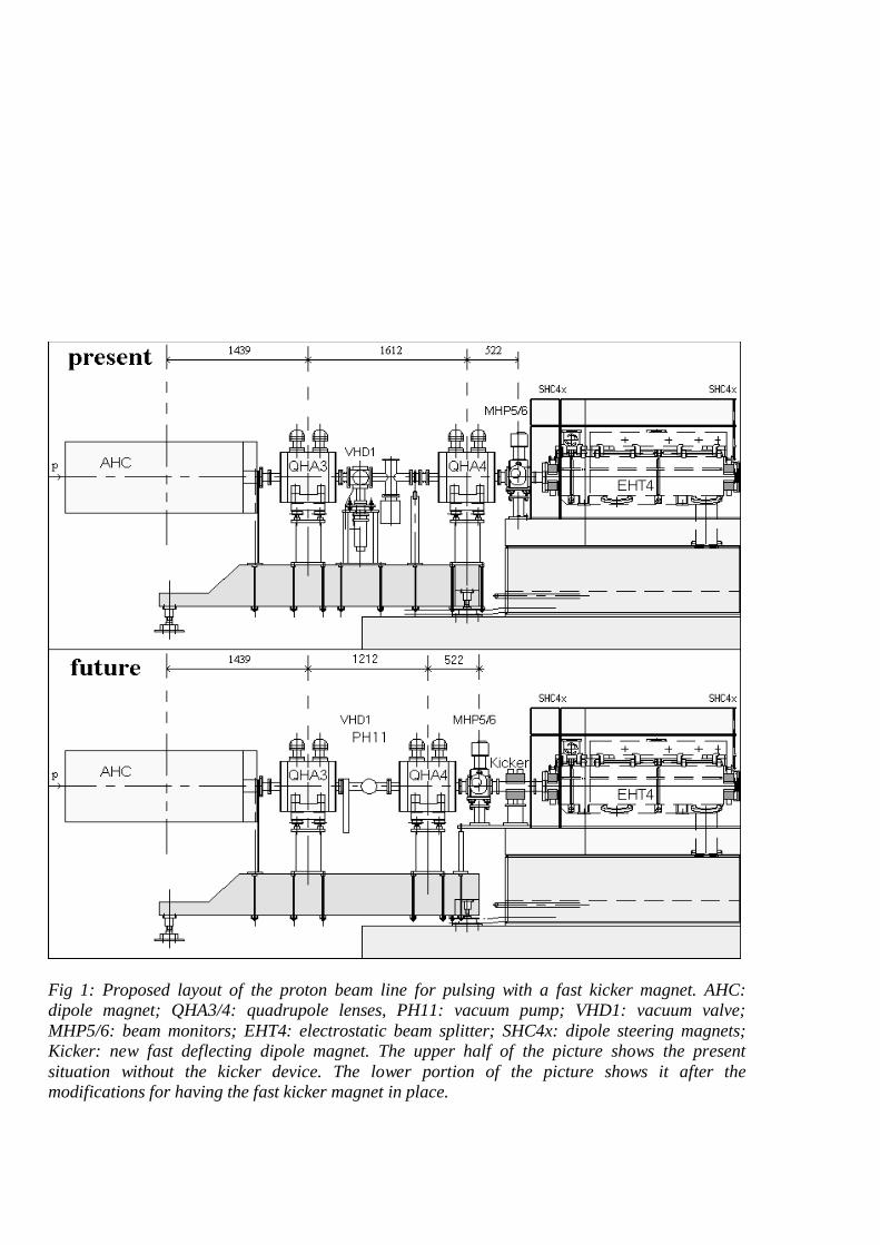
Fig 1: Proposed layout of the proton beam line for pulsing with a fast kicker magnet. AHC: dipole magnet; QHA3/4: quadrupole lenses, PH11: vacuum pump; VHD1: vacuum valve; MHP5/6: beam monitors; EHT4: electrostatic beam splitter; SHC4x: dipole steering magnets; Kicker: new fast deflecting dipole magnet. The upper half of the picture shows the present situation without the kicker device. The lower portion of the picture shows it after the modifications for having the fast kicker magnet in place.

QHA4
-0.061
QTC5
2.589
QTC6
-3.071
ABS
3.806C
uCu
MHP5
SKIK
SC4x
EHT
SC4x
MHP7
SD5Y
MHP9
SD6X
MHB1
KHNX
MHB2
KHNY
MH11
y
x
8 mm
8 mm
z12 m 15 m
Fig 2: Kicked proton beam. Lateral displacement produced by 1 mrad kicker amplitude equals to 6.8 mm at the ABS collimator. Total displacement produced by 6 mrad is 41 mm. The settings for the quadrupole lenses (QTC5 and QTC6) are as used for normal beam production.
QHA4
-0.061
QTC5
2.589
QTC6
-3.071
ABS
3.806C
uCu
MHP5
SKIK
SC4x
EHT
SC4x
MHP7
SD5Y
MHP9
SD6X
MHB1
KHNX
MHB2
KHNY
MH11
8 mm
8 mm
y
x
12 m 15 m z
Fig 3: The expected diameters of the 2 mA proton beam at the ABS collimator: 2σ(x) = 4 mm, 2σ(y) = 6 mm. The beam envelopes are as observed during past beam production times.

AHB
QHA1
QHA2
AHC
QHA3
QHA4
QTC5
QTC6
QHB7
QHB8
AHD1
QHA9
QA10
AHD2
QC11
QC12
QC13
QC14
QC15
QC16
QC17
QC18
AHU
AHV
AHSW
QG21
QG22
AHL
CuCu
Cu
C KHM1
KHM2
KHE0
KHE1
KHE2
KHE3
BHE1
BHE2
BHE3
SA1Y
MHC1
MHP1
SA2X
SA3Y
MHP3
MHP5
SKIK
SC4x
EHT
SC4x
MHP7
SD5Y
MHP9
SD6X
MHB1
KHNX
MHB2
KHNY
MH11
MH13
SB7X
MH15
MH17
SA8Y
SA9X
SB10
MH19
SA11
MH21
TM
MHB2
MH23
SB13
SB14
MH25
MH27
MH29
SB15
SB16
MH31
MH33
TE
MHB5
MHB6
SG21
MHC5
MP41
MP43
MHB7
MHB8
MHB9
y
90 mm
x
90 mm
10 m
z
0 m
Fig 5: The deflected proton beam to the Targets M and E and to the beam dump. The 5 shown central trajectories are 0.06 to 0.30 mrad off-axis (corresponding to 1 ÷ 5 % of the kicker amplitude of 6 mrad).
AHB
QHA1
QHA2
AHC
QHA3
QHA4
QTC5
QTC6
ABS
ABT
QBB1
QBB2
QBB3
QBB4
ABK1
QBA5
QBA6
ABK3
QBB7
CuCu
Cu
C KBN1
SA1Y
MHC1
MHP1
SA2X
SA3Y
MHP3
MHP5
SKIK
SC4x
EHT
SC4x
MHP7
SD5Y
MHP9
SD6X
MHB1
KHNX
MHB2
KHNY
MH11
SB1Y
MBP1
SB2Y
MBP3
SB3X
MBP5
MBP7
SB4Y
SB7X
MBP9
MB11
SA5Y
MB13
KBA2
MBH1
MBH3
MBB1
TUCN
y
60 mm
x
60 mm
0 m 10 m
z
Fig 4: The deflected proton beam to the proposed UCN facility. The 5 shown beam centroids are 0.06 to 0.30 mrad off-axis. (corresponding to 1 ÷ 5 % of the kicker amplitude of 6 mrad).

41 mm (6 mrad)
20 mm
8 mm
ABS- Collim.
beam to targets
beam to UCN
Losses on ABS
Fig 6: The beam situation in front of the magnetic septum magnet (ABS). If the transition with time were linear, then about 50% of the beam spill produced by the 6 mrad kick would be deposited on the (only) radiation-cooled ABS collimator (tungsten). The width of the collimator is 20 mm and the beam separation ~41 mm. The 4σ width of the 2 mA proton beam is expected to be about 8 mm.

0
15 %
85 %
100 % 99 % 95 %
time T0 T1 T2 T3 T4
kicker deflection angle
T5
T0 ~ -0.1 ms (0%) T1 = 0 ms (15%) T2 = 0.9 ms (85%) T3 = 1.2 ms (95%) T4 = 5 ms (99%) T5 = 10 ms (100%)
100 %
85 %
time T0 T1 T2 T3 T4
kicker deflection angle
T5
T0 ~ -0.1 ms (100%) T1 = 0 ms (85%) T2 = 0.9 ms (15%) T3 = 1.2 ms (5%) T4 = 5 ms (1%) T5 = 10 ms (0%)
15 %
5 % 1 % 0 %
Fig 7: Timing charts for the 2 fast kicker actions. Top: transition from beam to the targets to the UCN facility. Bottom: transition of beam from UCN facility to the targets M and E. Important is, that the transition time between 15 % and 85 % is as short as reasonably achievable.

1.8 mA
1.8 mA
time
time
I (UCN)
I (TE)
time
AVKI
0
0
0
4 s5 ms 5 ms
~2s~2s
600 s
Fig. 8: Time charts of the beam currents to the targets M and E and to the UCN target during a typical UCN kicker sequence. Preceding the main pulse of 4 s duration 2 test pulses of 5 ms duration for diagnostic purposes are shown. The third time chart shows the pulses (around 1 ms duration) applied to the interlock kicker (AVKI) for suppressing the beam during the switching periods.

Time schedule:
1 Test of beam interruptions of 1÷10 milliseconds with AVKI May 2001 2 Rearrange proton channel elements in front of EHT4 Shutdown 2002 3 Kicker power supply design 2001/2002 4 Fabrication of kicker power supply 2001/2002 5 Kicker magnet design 2001 6 Fabrication of kicker magnet 2001/2002 7 Laboratory tests with kicker magnet and power supply Spring 2002 8 Installation of kicker magnet and power supply Summer 2002 9 Test of kicking process with beam Summer 2002
Budget Proton-Beam kicker for UCN
Activity Responsible Money UCN (kFr)
Money GFA (kFr)
Manpower (MM)
Mechanical: Modification of p-channel for kicker magnet in front of EHT D. Suhi 10 3
Vacuum: Bellows, tubes, gaskets etc R. Knecht 15 1 Vacuum: New pump and valve in front of kicker magnet R. Knecht 40 1
Kicker Magnet (ferrite) D. George 20 3 Ceramic vacuum tube for kicker D. George 20 1 Kicker Power-Supply F. Jenny 25 10 Cabling and installation work A. Widmer 5 1 Control System (Kicker Magnet) I. Jirousek 12 3 VME crate + Frontend CPU I. Jirousek 13 1
Total 92 68 24
Table 1: Money and manpower requirements for an early demonstration of the functioning of the fast proton beam kicker device for the UCN facility.

Memorandum vom: 1. Juli 1999 An: A. Mezger WBGA/C25 von: U. Rohrer WLGA/D17 G. Heidenreich WMHA/C44 L. Rezzonico WBGA/C14 M. Werner WMHA/C30 G. Irminger WMHA/C12 E. Steiner WBGA/C22 T. Blumer WBGA/C25 Geschätzte Kollegen, An einem der nächsten LAAW-Meetings sollten wir dem UCN Projekt Team und anderen betroffenen Leuten erklären, wie wir uns gegenwärtig einen möglichen Strahl-Betrieb mit dieser neuen Experimentier-Einrichtung vorstellen, und was es dazu eventuell Neues braucht, um einen sicheren und für alle Beteiligten möglichst störungsfreien Strahl-Betrieb zu garantieren. Ich möchte Sie bitten, die Gedanken dazu auf den nächsten 2 Seiten kritisch anzuschauen und mir Ergänzungen, Korrekturen, Richtigstellungen usw. mitzuteilen. Besten Dank Direktschuss von 2 mAs Pulsen auf das UCN-Target. Es ist geplant, an Stelle des Piotrons in den nächsten Jahren eine Quelle für ultrakalte Neutronen (UCN) zu plazieren und deren Target bei Betrieb ca. alle 10-15 min mit einem kurzen 590 MeV Protonen-Strahl-Puls von ca. 2 mAs Ladung und einer Zeitdauer von einigen Sekunden zu

bestrahlen. Da die heutige Betriebsstruktur der Beschleuniger-Anlage auf reinen DC-Betieb ausgerichtet ist, bedeuten die Anforderungen der UCN an den Beschleuniger-Betrieb Neuland; die Methoden dazu müssen zuerst entwickelt werden. (Wegen der Target-Belastung und dem Beamloading bei den Kavitäten wird der Strahl heute nach einem Interlock relativ langsam innerhalb von etwa 30 sec hochgefahren.) Status der zu benutzenden Strahlführung ABS bis ABK2: Profil-Monitore: 0.6 mm x 10.0 mm Mo-Stäbe, relativ langsam, nicht synchronisiert. (* Schwerpunkts-Monitore: relativ langsam (<50 Hz) Ionisations-Kammern:Warn- und Interlock-Pegel für 20 µA DC “gesplittet” optimiert (** Steuer-Magnete: relativ langsam (ca. 1 sec von +max bis -max) SHC4x-Magnet: Weicheisen-Kern, Pyrothenax Spule (langsam) Abschirmung: maximal für 20 - 50 µA DC “gesplittet”. Wichtige Nebenbedingung: Voraussichtlich muss für unbestimmte Zeit in der EHT-Region immer noch der DC-Splitter für Pirex, Pif und NA3 (Backup) bereit gehalten werden. Es kann auch für den UCN-Betrieb von Vorteil sein, einen “gesplitteten” DC Pilotstrahl niediger Intensität von ca. 3 µA zur groben Einstellung der Optik und Zentrierung aufs Target zu haben. 2 Möglichkeiten der Puls-Erzeugung stehen bis jetzt zur Diskussion: Methode A: Die folgende Sequenz soll möglichst effizient und reproduzierbar via ein Computer Programm alle 10-15 Minuten durchgeführt werden können. Die totale Dauer dürfte 10-15 Sekunden nicht überschreiten. 1) Abstellen des Strahls auf TM, TE und SINQ. 2) SHC4x auf richtigen Wert für UCN-Direktschuss setzen. 3) Strahl möglichst schnell hochfahren bis 2 mAs erreicht sind. 4) Strahl abstellen. 5) SHC4x auf null setzen. 6) Normales Hochfahren des Strahls auf TM, TE und SINQ. Die Realisierung dieser Methode ist ohne apparativen Umbau möglich, deren praktische Durchführbarkeit wird jedoch wahrscheinlich dadurch erschwert werden oder sogar daran scheitern, dass der Strahl beim schnellen Hochfahren der Strahlintensität (üblicherweise mit KIP2) stark schiebt und daher vorzeitig ein Interlock erzeugt, weil der Strahl nicht schnell genug automatisch nachzentriert werden kann. Eine Alternative zur automatischen Zentrierung wäre ein tabellen-gesteuertes Magnet-Kompensations-Programm welches sich jedoch nur dann entwickeln und unterhalten lässt, wenn der Strahl in Richtung UCN langsam hochgefahren werden kann (praktisch DC-Strahl bis und mit voller Intensität). Zudem können die Kompensations-Parameter von Woche zu Woche nach einem Setup oder längeren Strahl-Unterbruch ändern. (DC-Strahl hoher Intensität aufs UCN-Target ist aus thermischen und radiologischen Gründen ausgeschlossen. Ein separater Beamdump in der Nähe vor dem UCN-Target ist aus Platzgründen nicht möglich.) Methode B: Der SHC4x Magnet muss zum schnellen Kickermagneten umgebaut werden und mit dem entsprechenden Speisegerät (typische Parameter: I=1000A, U=1000V, Tr=1µsec) versehen werden. Eine Umschaltung zwischen dem alten und dem neuen Speisegerät kann z.B. über einen Polumschalter bewerkstelligt werden. Bei dieser Methode sind keine Hochfahr-Probleme vorhanden. Es wird jedoch durch den Ein- und Ausschaltvorgang des Kickers mehr Strahlverluste

beim ABS-Schutzkollimator (Ein Umbau mit eventueller Wasser-Kühlung könnte sich aufdrängen.) und an anderen Orten entlang der beiden Strahführungen geben. (Je steiler die Flanken (einige µsec), desto besser sind die Chancen, dass es dabei kein Interlock gibt.) Zudem muss ein neuer SHC4x Magnet (ebenfalls zweiteilig ?) mit Pyrothenax-freier Spule und mit einem Kern aus Ferrit gebaut werden. Ob auf Pyrothenax (wegen Strahlenfestigkeit) ohne Lebendauer-Probleme verzichtet werden kann muss noch durch Messen der Strahlungspegel vor und nach dem EHT abgeklärt werden. Ein weiterer Vorteil dieser Methode ist die sehr kurze Ausfallzeit des Strahls zu den Targets M und E und SINQ von nur ca. 1 sec pro 10-15 min. Zudem entfällt der Beam-Loading Effekt an den Ring-Kavitäten beim raschen Hochfahren der Strahintensität (siehe Methode A). Strahl-Optik: Die Strahlanfangsbedingungen (projektierte x- und y-Emittanzen) können mit einem Transport Enveloppen-Fit unter Verwendung der Messungen der Profilbreiten zwischen Ringausgang und Target M berechnet werden. Ein anschliessender Quadrupol-Fit erlaubt es dann die Erregungen der Quadrupole zwischen ABS und dem UCN-Target vor dem Kicken (oder Ablenken) richtig zu setzen. Es wird angenommen, dass die Erregungen der Quadrupole vor dem EHT nicht verstellt werden müssen/dürfen, da diese gemeinsam vom Strahl auf Target M oder Target UCN genutzt werden. (Eventuell muss für den UCN-Kicker-Modus eine etwas andere Optik zum Target M eingestellt werden als für den DC-Splitter-Betrieb.) Strahl-Zentrierung: Momentan und wahrscheinlich auch in Zukunft ist es unmöglich den Strahl beim raschen Hochfahren innerhalb von einigen Sekunden ständig genügend genau zentriert zu halten (Magnete und Speisegeräte reagieren nicht schnell genug). Falls man jedoch sehr schnell messende (1kHz) Schwerpunks-Sonden (mit Zusatzelektronik, die das Ablesen und Speichern der Schwerpunkte über die letzten paar Sekunden erlaubt) hätte, könnten die Lagen des Strahls an den verschiedene Messstellen während des Hochfahrens bis zum etwaigen Interlock monitoriert werden um dann die entsprechenden (Steuer-)Magnet Settings vor dem nächsten Versuch (nach einigen Minuten ?) gezielt mit einer “virtuellen Zentrierung” in die richtige Richtung zu verstellen. *) Synchronisierte Profilmonitore: Um wenigstens die Daten eines Strahl-Profils pro Puls aufnehmen zu können, müssen die Durchläufe der entsprechenden Profilmonitore mit der Dauer des Strahl-Pulses synchronisiert werden können. Dies bedeutet, dass der Durchlauf schon vor dem Start des Strahl-Pulses erfolgen muss. Zudem sollte diese Zeitdifferenz für jeden der benötigten Profilmonitore individuell einstellbar sein um dem Strahl-Breiten- und Geschwindigkeits-Unterschied (Tachometer ?) zu begegnen. Falls dies machbar ist, sollte bei der Verwendung der Kicker-Variante und bei konstanten Strahlbedingungen das Erstellen einer mit Transport gefitteten Strahlenveloppe nach etwa 2-3 Stunden Betrieb möglich sein. **) Abschalt-Pegel und Geschwindigkeiten der Ionisations-Kammern. Bei einer Strahlintensität von 30 µA beträgt die Zeit bis zum Durchschmelzen von rostfreiem Stahl etwa 60 sec, während sie bei 1.7 mA nur noch 10 msec beträgt (Strahldurchmesser in beiden Fällen etwa 4 mm). Das Einbauen von Verzögerungen ins Interlock-System der Ionisationskammern sind daher verboten. (Für die Abschaltzeiten gelten die gleichen Regeln wie für den Hauptstrahl.) Da bei gut eingestelltem Direkt-Strahl die Verluste viel kleiner sind als bei gesplittetem Strahl gleicher Intensität, können die Interlock-Pegel der Ionisationskammern eventuell auch während des UCN-Strahlpulses gleich gelassen werden. Sonst müssten sie für die Dauer des Strahl-Pulses mit einem Programm dynamisch hochgesetzt werden können.

Memorandum vom: 5. August 2002 An: R. Dölling WBGA/C14 von: U. Rohrer WLGA/D17 P-A. Duperrex WBGA/C14 A. Mezger WBGA/C25
I. Jirousek WBGA/C18 M. Daum WLGA/D31 z.K: P-A. Schmelzbach
Ausbau des 590 MeV Protonen-Strahls für UCN-Kicker-Betrieb.
1. Einleitung: Nachfolgend einige Gedanken, die einige der zukünftigen Bedürfnisse für die Bewältigung des geplanten Kicker-Strahlbetriebs für UCN definieren sollen. Es gibt dabei einige Besonderheiten zu beachten, die es nicht erlauben den Setup und den Routine-Betrieb wie auf die vom Betrieb zu den Targets M & E gewohnte Art und Weise zu bewerkstelligen. Dies erfordert daher, dass bei den Strahl-Diagnostik-Elementen und derer Treiber-Software einige gewichtige Änderungen bzw. Erweiterungen vorzunehmen sind. 2. Strahl-Optik: Die Strahlanfangsbedingungen (projektierte x- und y-Emittanzen und Dispersion) können jederzeit bei HE-Strahlbetrieb mit einem Transport Enveloppen-Fit unter Verwendung der Messungen der Profilbreiten (MHP1 – MHP22) am aktuellen p-Strahl zwischen Ringausgang und Target M berechnet werden. Ein anschliessender Quadrupol-Fit erlaubt es dann die Erregungen der Quadrupole zwischen ABS und dem UCN-Target vor dem Kicken (oder Ablenken) richtig zu setzen. Es wird vorausgesetzt, dass die Erregungen der Quadrupole vor dem ABS-Septum (QHA1 – QHTC6) nicht verstellt werden müssen/dürfen, da diese gemeinsam vom Strahl auf Target M oder Target UCN genutzt werden. (Eventuell muss für den UCN-Kicker-Modus eine etwas andere Optik [schmäler beim EHT] zum Target M eingestellt werden, als für den DC-Splitter-Betrieb.) Siehe dazu die Abbildungen 1-4. Die für diese Strahloptik zum UCN-Target benötigten Quadrupol DAC-Werte sind in Tabelle 1 aufgelistet.
Name DAC
QHA1 -768QHA2 -72QHA3 -206QHA4 -33QHTC5 1236QHTC6 -1466QBB1 2309QBB2 -2046QBB3 2113QBB4 -2225QBA5 -2317QBA6 1975QBB7 2046
Tabelle 1
3. Strahl-Zentrierung: Aus mindestens 2 Gründen (Abschirmung des p-Strahls nur für 20 µA kontinuierlich und ungenügende Kühlleistung für das UCN-Target) ist es nicht möglich den p-Strahl in Richtung UCN langsam auf 1.8 mA mit gelegentlichem Nachzentrieren hochzutunen. Falls man jedoch schnell messende (f=1kHz) Schwerpunks-Sonden (BPMs mit Zusatzelektronik, die das Ablesen und Speichern der Schwerpunkte über die letzten paar Sekunden erlauben) hätte, könnten die Lagen

des Strahls an den verschiedene Messstellen während des Hochfahrens bis zum etwaigen Interlock oder während eines kurzen Strahl-Pulses von 5 msec Dauer simultan monitoriert und abgespeichert werden. Dannach müssen diese BPM-Messwerte vom Kontroll-System ausgelesen werden und die entsprechenden (Steuer-)Magnet-Settings vor dem nächsten Versuch (nach einigen Sekunden) mit den während dieser „Kicker-Pause“ berechneten neuen Werten in die richtige Richtung verstellt werden (“virtuelle Zentrierung”). Die zu ersetzenden Schwerpunktsmonitore (beinhaltet Boxen, Bälge, Abstützungen und dazugehörende Elektronik) sind MBP1 – MBP14 (7 Paare). Der letzte Strahl-Abschnitt zwischen ABK1 und UCN-Target hat keine BPMs sondern nur 2 Paare von Harfen-Sonden eingebaut. (Begründung siehe Abschnitt 6.) Daher müssen für eine vollständige Zentrierung bis zum UCN-Target neben den MBS-Monitoren auch noch während der Strahl-Pulse die Signale an je einem horizontalen und vertikalen Harfen-Monitor aufgezeichnet und ausgelesen werden. Der letzte Zentrierschritt lautet dann: ABK2 MBH1x (oder MBH3x) horizontal SBA5y MBH2y (oder MBH4y) vertikal 4. Synchronisierte Profilmonitore: Um die Daten mehrerer Strahl-Profile pro Kicker-Puls aufnehmen zu können, müssen die Durchläufe dieser Profilmonitore (PM) während der Dauer des Strahl-Pulses (∆t = 4 bis 8 sec) mit einem zeitlichen Abstand von circa 1 Sekunde gestaffelt werden können. Dabei sollen die gewonnenen Profildaten lokal zwischengespeichert werden und erst nach Beendigung aller Durchläufe vom Kontroll-System in der darauf folgenden Strahl-Pause ausgelesen und ausgewertet werden. Dies bedeutet, dass der Durchlauf von einem bestimmten Set von PMs schon vor dem Start des Strahl-Pulses eingeplant werden muss. Falls dies alles machbar ist, sollte bei der Voraussetzung von über längere Zeitabschnitte herrschenden konstanten Strahlbedingungen das Erstellen einer mit Transport gefitteten Strahl-Enveloppe nach etwa 2-3 Kicker-Pulsen (wahrscheinlicher zeitlicher Abstand von Puls zu Puls 10 – 15 Minuten) möglich sein. Zu beachten ist auch die Tatsache, dass die Profilmonitore MBP1 – MBP14 noch von der alten Bauweise (Wolfram-Stäbe) sind und durch sogenannte Bügel-Monitore ersetzt werden müssen, da sie ja nun auch für Ströme von 1.8 mA und höher brauchbar sein sollen. Da man aber nach wie vor mit dem DC-Splitter (EHT) bis zu 20 µA DC abschälen will, muss es auch möglich sein die Profile noch bei 0.1 – 1.0 µA zu sehen. Dies bedeutet wahrscheinlich, dass Drähte zu wenig Empfindlichkeit liefern und durch 50 µm dicke Folien von 2 – 3 mm Tiefe (in Strahlrichtung) ersetzt werden müssen. 5. Abschalt-Pegel und Geschwindigkeiten der Ionisations-Kammern. Bei einer Strahlintensität von 30 µA beträgt die Zeit bis zum Durchschmelzen von rostfreiem Stahl etwa 60 sec, während sie bei 1.8 mA weniger als 10 msec beträgt (Strahldurchmesser in beiden Fällen etwa 4 mm). Das Einbauen von Verzögerungen ins Interlock-System der Ionisationskammern ist daher verboten. (Für die Abschaltzeiten bei UCN-Betrieb gelten die gleichen Regeln wie für den Hauptstrahl in Richtung der Targets M und E.) Da erfahrungsgemäss bei einem gut eingestellten, ungesplitteten Strahl von 20 µA die Verluste viel kleiner sind als bei einem gesplitteten Strahl gleicher Intensität, können die Interlock-Pegel der Ionisationskammern eventuell auch während des gekickten UCN-Strahlpulses von 1.8 mA gleich gelassen werden wie für den 20 µA-Splitterbetrieb. Sonst müssten sie für die Dauer des Strahl-Pulses von einigen Sekunden mit einem Programm dynamisch hochgesetzt werden können. 6. Harfen-Sonden. Im neuen Strahl-Ast zwischen ABK2 und UCN-Target werden 2 Harfen-Sondenpaare (MBH1x – MBH4y, je 16 Drähte) eingebaut. Hier wurden Harfen-Sonden gewählt, weil dieser Strahl-Abschnitt erstens neu ist und zweitens mit Harfen-Sonden die Möglichkeit besteht sie ständig im Strahl stehen zu lassen, sodass auch die kurzen Strahlpulse von einigen Millisekunden detektierbar sind. Sie sind also sozusagen PM und BPM in einem. Die Elektronik dazu wurde vor einiger Zeit bereits entwickelt und beim LIZOR-Experiment bereits getestet. Der mechanische Layout liegt auch

bereits vor. Die 2σ-Strahlbreiten am Orte dieser Sonden können aus Abbildung 3 herausgelesen werden. 7. Blenden (Halo)-Monitore. Etwa 3 Meter vor dem UCN-Target befindet sich ein Kollimator, der die für das UCN-Target schädlichen Strahlschwänze abschneidet. Ein aus 4 Blech-Segmenten bestehender Blenden-Monitor (MBB1o/u/l/r) ist daran befestigt. Dieser wird ähnlich gebaut sein wie MHB5 nach dem Target E. Dieser Monitor dient zur permanenten Überwachung der x- und y-Strahlbreiten vor dem UCN-Target. Sollte zum Beispiel das Speisegerät des QBB7-Quadrupols ausfallen, so würde der Strahl auf dem UCN-Target zu klein im Durchmesser werden und dieses eventuell beschädigen. Da in diesem Fall die MBB1-Sonde bei 1.8 mA nichts mehr anzeigen würde kann dadurch ein Interlock-Signal generiert werden. Dazu braucht es die gleiche Elektronik (generiert und überwacht Verhältnis zwischen Verlust- und Strom-Anzeige) wie zwischen Target E und Beamdump BHE. 8. Spezieller Interlock-Kanal. Da laut SINQ-Target Spezialisten das „Zurück-Kicken“ des p-Strahls vom UCN-Target aufs SINQ Flüssigmetall-Target nach einigen Sekunden Strahl-Unterbruch zur SINQ aus thermischen Gründen nicht erlaubt ist, muss bei Beginn des Zurückschalt-Vorganges von der Steuerung ein Interlock an den Beschleuniger (Beam-off) Signal generiert werden, sodass die normale Hochfahr-Prozedur den Strahl während etwa 30 sec wieder auf die Targets M, E und SINQ zurück bringt. Dies gilt nicht für die kurzen (5 msec) Test-Strahl Pulse.

Abb. 1: Enveloppen-Fit des p-Strahles zwischen Ring-Extraktion und Target-M. Strahl vom 19. Juli 2002. Strahlstrom = 1.8 mA. Verwendete Profile: MHP1 bis MHP22. Die gemessenen 2σ-Breiten sind mit ⊥Τ-Symbolen gekennzeichnet.

Abb 2: Simultan-Display von Strahl auf Target-M (Enveloppen-Fit von Abb 1) und Strahl in Richtung UCN mit identischen Anfangs-Bedingungen bei der Ringextraktion. Aperturen und Beschriftung sind für Strahlführung zum Target M.

Abb 3: Berechnete Strahl-Enveloppe des p-Strahls zwischen Ring-Extraktion und UCN-Target. Die Anfangsbedingungen sind die gleichen wie in Abb 1 und 2. Man beachte die starke Aufblaswirkung des Quadrupols QBB7. Die 2σ-Strahlbreiten bei den Labels MBH1 und MBH3 (Harfen) sind hieraus ablesbar.

Abb 4: Dito wie Abb 3, jedoch mit anderer Skalierung in x und y. Die 2σ-Werte der Profilbreiten MBP1 – MBP14 sind hieraus gut ablesbar.

FIRST BEAM TESTS WITH THE FAST KICKER MAGNET FOR THE ULTRA COLD NEUTRON FACILITY
U. Rohrer, M. Daum, D. George, F. Jenni, A. C. Mezger
The proposed new type of ultra cold neutron source to be built and installed at PSI requires the full intensity 590 MeV proton beam (currently 1.85 mA) to be switched onto the spallation target, located at the center of the UCN facility, for about 8 seconds every 15 minutes. For this purpose, a fast kicker magnet (rise-time ≤ 1 ms) located just in front of the existing DC-splitter device (EHT) has been proposed. One conclusion of the “Technical Review of the UCN Source Project Proposal at PSI”, which took place on Nov.14 and 15, 2000, was that an early demonstration of the functioning of the fast kicking process was desirable before embarking on the overall construction effort for the whole facility. In the meantime, the required magnet, power-supply and control system have been manufactured by PSI. During the shutdown at the beginning of 2002, the required space for installing the kicker magnet had already been accomplished by modifying the proton beam line in front of the DC-splitter. The ceramic vacuum chamber for the magnet was also installed at this time. On December 4, 2002 a successful test of the fast switching process with 20 µA of proton beam intensity could be performed for the first time.
INTRODUCTION Fig. 1 shows the region where the kicker magnet (AHKI) is placed. This device is mounted just in front of the DC-splitter (EHT4) because it is necessary to have it as close to the EHT4 as possible in order to keep the displacement of the beam - and therefore the losses produced by it at the EHT4 foil - as low as possible (see Fig. 2). The space requirements for the kicker are about 40 cm in the beam direction. During the last shutdown, the profile monitor-box MHP5/6 and the quadrupole QHA4 were moved towards the cyclotron by this amount. In order to gain this space, the vacuum pump PH11 and the valve VHD1 were replaced by less space-consuming modern devices (see Fig. 1). The optical influence of this modification is minimal and therefore does not affect the quality of the proton beam.
Fig. 1: New layout of the section of the proton beam line for switching with the fast kicker magnet. AHC: bending magnet; QHA3/4: quadrupole lenses, PH11: vacuum pump; VHD1: vacuum valve; MHP5/6: beam monitors; EHT4: electrostatic beam splitter; SHC4x: steering magnets; Kicker: newly installed fast deflecting magnet [2].
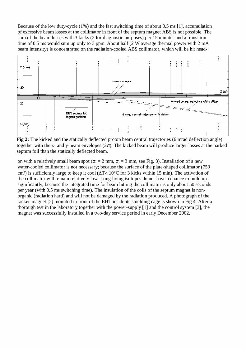
Because of the low duty-cycle (1%) and the fast switching time of about 0.5 ms [1], accumulation of excessive beam losses at the collimator in front of the septum magnet ABS is not possible. The sum of the beam losses with 3 kicks (2 for diagnostic purposes) per 15 minutes and a transition time of 0.5 ms would sum up only to 3 ppm. About half (2 W average thermal power with 2 mA beam intensity) is concentrated on the radiation-cooled ABS collimator, which will be hit head-
on with a relatively small beam spot (σx = 2 mm, σy = 3 mm, see Fig. 3). Installation of a new water-cooled collimator is not necessary; because the surface of the plate-shaped collimator (750 cm²) is sufficiently large to keep it cool (∆T< 10°C for 3 kicks within 15 min). The activation of the collimator will remain relatively low. Long living isotopes do not have a chance to build up significantly, because the integrated time for beam hitting the collimator is only about 50 seconds per year (with 0.5 ms switching time). The insulation of the coils of the septum magnet is non-organic (radiation hard) and will not be damaged by the radiation produced. A photograph of the kicker-magnet [2] mounted in front of the EHT inside its shielding cage is shown in Fig 4. After a thorough test in the laboratory together with the power-supply [1] and the control system [3], the magnet was successfully installed in a two-day service period in early December 2002.
Fig 2: The kicked and the statically deflected proton beam central trajectories (6 mrad deflection angle) together with the x- and y-beam envelopes (2σ). The kicked beam will produce larger losses at the parked septum foil than the statically deflected beam.

FIRST TESTS WITH BEAM At the moment there is no high power beam dump for 2 mA available in the NA-beam line branch, which leads to the future UCN-source. Therefore, the first kicker tests with beam could only be performed with up to 20 µA onto the PIREX target station. Because of safety requirements, the interlock levels for the MHC1 and MHC2 current monitors in the main beam line branch leading to the targets M and E had to be set temporarily to 25 µA as is the case for the MBC1 current monitor in the NA-beam line leading to PIREX. We performed the first kick with 2 µA for 2 seconds in order to avoid any vacuum leak. A running live-display program with a repetition rate of 2 Hz displaying the measured beam currents, the beam position monitor (BPM) readings and the losses along the beam line leading to the PIREX target showed immediately that the beam reached the PIREX target without any corrections to the magnet settings, which were established with the statically deflected beam by using the SHC4x magnets of the DC-splitter for steering the beam to the PIREX target. The central trajectories of the 2 modes are shown in Fig 2. They are very close. Afterwards, the beam intensity was increased to 10 and then to 20 µA. Table 1 shows a hardcopy of the first beam kick with 20 µA. The values shown look almost the same as for the statically deflected beam with the exception that the losses along the beam line were about a factor of 2 higher. This is probably due to the fact that we could not carefully center the beam and that there are larger losses at the DC-splitter’s septum-foil in the park position. Fig. 5 shows an envelope fit using the profile data gained from different consecutive beam kicks of 8 seconds duration. During each of these beam-on periods, 3 to 4 different pre-selected profiles
41 mm (6 mrad)
20 mm
8 mm
ABS - Collim.
b eam to t argets
b eam to UCN
Losses on ABS
Fig 3: The beam situation in front of the magnetic septum magnet (ABS). If the transition with time were linear, then about 50% of the beam spill produced by the 6-mrad-kick would be deposited on the purely radiation-cooled ABS tungsten collimator. The width of the collimator is 20 mm and the beam separation ca. 41 mm. The 4σ width of the 2 mA proton beam is expected to be about 8 mm. The 20 mm sweep over the collimator is done within 200 µs [1].
Fig 4: Photograph of the kicker magnet. 1: adjustable base plate, 2: ferrite yoke, 3: partially opened shielding cage, 4: upper coil, 5: current leads, 6: lower coil, 7: ceramic vacuum tube, 8: bellows. See also reference [2].

MHC1 23.3 MBC1 18.1
MBS1 -15 MCS1 0.3MBS2 MCS2 -0.9MBS3 -7.4 MCS3 4MBS4 0.8 MCS4 0.6MBS5 -6.8 MCS5 -5.5MBS6 -0.3 MCS6 1.5MBS7 -6.1 MCS7 5.2MBS8 -0.4 MCS8 -1.7MBS9 -2.1 MCS9 7.2
MBS10 -1 MCS10 -0.8MBS11 -18.7 MCS11 0.9MBS12 -0.2 MCS12 -0.4MBS13 -10.4MBS14 0.8
MBI1 2.3 MCI1 0.4MBI2 9 MCI2 4MBI3 5.7 MCI3 20.3MBI4 0.1 MCI4 0.1
MBI10 0.1
Beam loss monitors in nA
Beam currents in Micro-Amps
Beam position monitors in mm
Table 1: A Live-Display of the first beam-kick with 20 µA of beam current. Displayed are the relevant beam current monitors, the BPMs and the loss monitors. (MHC1 is optimized for 2 mA and has not been recalibrated for low currents.)
could be run and the graphic output stored on a computer screen. Because of the 1%-duty-cycle of the kicker power-supply, we had to wait 15 minutes for the next beam kick. It took us about 2 hours to get the required profile data to complete a 2σ-width data set for performing the desired envelope fit. A comparison of the resulting fit with the one gained from profile data taken with the direct, statically deflected beam (not shown in this article), showed no significant differences within the statistical fluctuation. It should be mentioned here that the quality of the 20 µA-beam was not very good. Prior to our beam shift, the cyclotron had been optimized to produce 1.85 mA and there was no time available to retune and improve the quality of the required low intensity proton beam.

FUTURE Developments Fig. 6 shows the expected beam envelopes of the 2 mA beam between the 590-MeV cyclotron-extraction and the planned UCN spallation target. The emittance used is the one measured today with the 1.85 mA beam to the targets M and E. We do not expect that it will be significantly different when the UCN facility is ready. In order to save time and costs, several items necessary
Fig 5: Envelope fit with the measured beam profile widths of the kicked proton beam at 20µA intensity. The measured 2σ-widths are marked with ⊥ and T, whereas the solid curves represent the fitted x- and y-envelopes. The dotted line is an assumed 1-permille-dispersion trajectory. Per kick only 3 to 4 profiles could be recorded. Therefore 7 runs with a waiting time of about 15 minutes in between were needed to gather the required data.
Fig. 6: Beam envelopes of the proton beam transport to the planned UCN facility. The emittance used is that of the 1.85 mA beam in December 2002. In order to keep the beam losses low, the beam size is kept as small as possible along the first 58 m from the cyclotron extraction to the last quadrupole lens. The latter acts as a beam-widener on the last 12 m so that, at the UCN spallation target, the beam size reaches the required 1σ-width of 40 mm in both transverse directions. On the last 12 m, several pairs of ↑↓ indicate the relatively large aperture size (vacuum tube, collimator and target) of the new section of beam line for the UCN facility. About half of this last 12 m section is already installed but not yet equipped with the planned diagnostic elements and not yet tested with beam.

for UCN-production were not available for the first beam tests, but are required to be operational by 2006: (1) During the beam pulse of 8 seconds, the efficiency of collecting beam profiles at 2 mA of beam intensity should be improved by synchronization of the profile monitors with the beam kicker. (2) 2 pairs of harp monitors for the new section of beam line between QBB7 and the UCN target. They have the advantage of being profile monitor and BPM in one device and being able to stay in the beam continuously. (3) In order to detect the beam position along the beam line during short beam pulses of 5 ms duration, new fast BPMs with a sampling rate of 1 kHz are required. During this short time interval of beam, no interlock will turn off the beam and no damage to any component will occur. (4) At the collimator located in front of the UCN-target, a halo monitor consisting of 4 segments will be mounted. This fast device is capable of detecting small beam sizes, which could destroy the target. (5) Because of the relatively weak radiation shielding, the intensity of the beam line leading to the UCN target cannot be tuned up slowly to 2 mA. A ‘Virtual beam centering program’ is required. This program has to process the beam centers recorded by the fast detecting BPMs during a short beam pulse of 5 ms duration. During the recovery time of the kicker power supply, the program computes and sets the required corrections of the currents of the beam line bending and steering magnets. A second short pulse is used to confirm that the beam is well centered and that the main pulse of 8 seconds duration will cause no interlock due to excessive losses. REFERENCES [1] F. Jenni, Ein schnelles, präzises Speisegerät für den UCN-Kicker, LOG-Jahresbericht 2002.
[2] D. George, UCN-Kicker magnet, Scientific and Technical Report 2002, VI.
[3] T. Korhonen, First operation of a VME DSP-based controller board, Scientific and Technical Report 2002, VI.

- 33 -
Memorandum Datum: 21. Sept. 2004
Von: Urs Rohrer Telefon: 4035 Raum: WLGA/121 E-mail: [email protected]
An: R. Reckermann, M. Lüthy, M. Krenke, A. Mezger, M. Graf, R. Erne, S. Adam, R. Dölling, U. Frei, P.A. Duperrex, U. Müller, T. Korhonen, R. Käch, U. Heidelberger, R. Knecht, R. Kobler, M. Müller, H.P. Haller, B. Amrein, R. Reiser, M. Daum
Shutdown-2005-Arbeiten im Protonen-Kanal für UCN
Liebe Kollegen, 1) Profilmonitor Umbau: Im kommenden Shutdown-2005 sollen wegen UCN-Tauglichkeit die sieben Profilmonitor/Schwerpunktsmonitor-Boxen (MBP1-MBP14 und MBS1-MBS14) der Protonenstrahllinie zwischen den Ablenkmagneten ABS und ABK2 ausgewechselt werden. (Die jetzt eingebauten Profilmonitore sind nicht hochstromtauglich. Die neuen Boxen sind im Laufe dieses Jahres von M. Graf und seinem Team bereitgestellt worden.) Zudem wird im gleichen Shutdown-2005 die PM-Steuerung erneuert. Es ist von Vorteil für diese neue Steuerung, wenn auch die Profilmonitore im B-Ast auf den neuen Hochstrom-Typ umgebaut sind. Die je zwei Wellen-Bälge die zu einer Box gehören müssen durch Membran-Bälge (von der Vakuum-Gruppe bereitgestellt) ersetzt werden. Dadurch fehlt an gewissen Orten die longitudinale Abstützung der angrenzenden Vakuum-Rohre, was durch Anbringen von zusätzlichen Abstützungen an gewissen Orten korrigiert werden muss (Ad-hoc Beschlüsse des Montage-Teams unter Anleitung von Max Graf). Die Bügel der Profilmonitore sollen nicht mit Drähten sondern mit Folien ausgerüstet werden, damit die Empfindlichkeit für den im Jahre 2005 ausschliesslich noch stattfindenden 15 Micro-Ampère Betrieb für den Patienten-Betrieb an Gantry-1 sicher gewährleistet ist. Um den Aus- und Einbau bei der Box zwischen ABS und ABT (MBP1-MBS1) wegen schlechter Zugänglichkeit zu erleichtern, muss dort das Bunker-Dach abgedeckt werden. Um Erfahrung zu sammeln beginnt man den Umbau am besten mit den zwei leicht zugänglichen Boxen zwischen den Ablenkmagneten ABK1 und ABK2 (kleiner Strahlungs-Pegel). 2) Harfen-Monitor Einbau: Ebenfalls im kommenden Shutdown-2005 sollen die jetzt in der Werkstatt hergestellten Harfen-Monitore (MBH1/2 und MBH3/4) zwischen ABK2 und UCN-Target eingebaut werden. Dazu muss die schon eingebaute Lokal-Abschirmung entfernt werden. Da es sich bei den MBHs um eine Neuentwicklung handelt, kann es sein, dass es Abänderungen braucht. (Vakuum-Dichtheit der Anschlüsse und Passen der Lokalabschirmung um die Monitore herum sind zumindest im Kanal zu testen.) Die Harfen-Monitore können im Jahre 2005 noch nicht mit Strahl getestet werden, da in der HE-Periode 2005 kein Strahl aufs UCN-Target möglich ist. Die Steuer/Mess-Kabel für die Harfenmonitore von der Bedienungsebene zum Elektronik-Schrank sind schon verlegt, jedoch noch ohne Stecker. Da der Kanal im Shutdown-2005 geöffnet ist, sollen diese fehlenden Stecker montiert werden. Bevor die Harfen-Monitore endgültig eingebaut werden, soll jedoch die Funktionstüchtigkeit ihrer Mechanik noch im Labor gründlich getestet werden. Daher kann bei ev. nötigen grösseren Modifikationen der finale Einbau um ein Jahr auf den Shutdown-2006 verschoben werden.

- 34 -
Memorandum Datum: 21. Sept. 2004
Von: Urs Rohrer Telefon: 4035 Raum: WLGA/121 E-mail: [email protected]
An: R. Reckermann, M. Lüthy, M. Krenke, A. Mezger, M. Graf, R. Erne, S. Adam, R. Dölling, U. Frei, P.A. Duperrex, U. Müller, T. Korhonen, R. Käch, U. Heidelberger, R. Knecht, R. Kobler, M. Müller, H.P. Haller, B. Amrein, R. Reiser, M. Daum
Shutdown-2005-Arbeiten im Protonen-Kanal für UCN
Liebe Kollegen, 1) Profilmonitor Umbau: Im kommenden Shutdown-2005 sollen wegen UCN-Tauglichkeit die sieben Profilmonitor/Schwerpunktsmonitor-Boxen (MBP1-MBP14 und MBS1-MBS14) der Protonenstrahllinie zwischen den Ablenkmagneten ABS und ABK2 ausgewechselt werden. (Die jetzt eingebauten Profilmonitore sind nicht hochstromtauglich. Die neuen Boxen sind im Laufe dieses Jahres von M. Graf und seinem Team bereitgestellt worden.) Zudem wird im gleichen Shutdown-2005 die PM-Steuerung erneuert. Es ist von Vorteil für diese neue Steuerung, wenn auch die Profilmonitore im B-Ast auf den neuen Hochstrom-Typ umgebaut sind. Die je zwei Wellen-Bälge die zu einer Box gehören müssen durch Membran-Bälge (von der Vakuum-Gruppe bereitgestellt) ersetzt werden. Dadurch fehlt an gewissen Orten die longitudinale Abstützung der angrenzenden Vakuum-Rohre, was durch Anbringen von zusätzlichen Abstützungen an gewissen Orten korrigiert werden muss (Ad-hoc Beschlüsse des Montage-Teams unter Anleitung von Max Graf). Die Bügel der Profilmonitore sollen nicht mit Drähten sondern mit Folien ausgerüstet werden, damit die Empfindlichkeit für den im Jahre 2005 ausschliesslich noch stattfindenden 15 Micro-Ampère Betrieb für den Patienten-Betrieb an Gantry-1 sicher gewährleistet ist. Um den Aus- und Einbau bei der Box zwischen ABS und ABT (MBP1-MBS1) wegen schlechter Zugänglichkeit zu erleichtern, muss dort das Bunker-Dach abgedeckt werden. Um Erfahrung zu sammeln beginnt man den Umbau am besten mit den zwei leicht zugänglichen Boxen zwischen den Ablenkmagneten ABK1 und ABK2 (kleiner Strahlungs-Pegel). 2) Harfen-Monitor Einbau: Ebenfalls im kommenden Shutdown-2005 sollen die jetzt in der Werkstatt hergestellten Harfen-Monitore (MBH1/2 und MBH3/4) zwischen ABK2 und UCN-Target eingebaut werden. Dazu muss die schon eingebaute Lokal-Abschirmung entfernt werden. Da es sich bei den MBHs um eine Neuentwicklung handelt, kann es sein, dass es Abänderungen braucht. (Vakuum-Dichtheit der Anschlüsse und Passen der Lokalabschirmung um die Monitore herum sind zumindest im Kanal zu testen.) Die Harfen-Monitore können im Jahre 2005 noch nicht mit Strahl getestet werden, da in der HE-Periode 2005 kein Strahl aufs UCN-Target möglich ist. Die Steuer/Mess-Kabel für die Harfenmonitore von der Bedienungsebene zum Elektronik-Schrank sind schon verlegt, jedoch noch ohne Stecker. Da der Kanal im Shutdown-2005 geöffnet ist, sollen diese fehlenden Stecker montiert werden. Bevor die Harfen-Monitore endgültig eingebaut werden, soll jedoch die Funktionstüchtigkeit ihrer Mechanik noch im Labor gründlich getestet werden. Daher kann bei ev. nötigen grösseren Modifikationen der finale Einbau um ein Jahr auf den Shutdown-2006 verschoben werden.

- 35 -
IMPROVEMENTS OF THE SAFETY ENVIRONMENT FOR THE UCN-KICKER MAGNET
U. Rohrer, R. Dölling
After a successful test of the UCN-kicker at the end of 2002, its ceramic tube did not survive the HE-beam period 2003, because the metallic joint at its entrance got overheated by some temporarily misguided proton beam, and started to leak. A new ceramic tube has now been inserted with three protective diagnostic elements added in its environment, which should avoid any further damage of this piece of vacuum tube. An additional benefit of this upgrade is the improved awareness for minimizing the beam spill in the region of the kicker magnet.
INTRODUCTION
In December 2002 it was successfully demonstrated in situ with beam, that a newly designed fast kicker magnet fulfils the requirements for switching the beam normally going to the targets M, E and SINQ into the beam line leading to the future UCN target forth and back in less than 1 ms (see [1], [2]). But during the HE-period of 2003 some overheating caused by a temporarily misguided beam produced a vacuum leak at the soldering joint of the ceramic tube at its entrance. The kicker magnet and its ceramic tube had to be removed until a solution with some diagnostics to detect false beam conditions at this location was found and successfully tested.
Fig. 1: Photo of the ceramic tube with the 4-segment (l/r/o/u) halo monitor (MHH1), the thermo couples (AHK1TL/R) on each side of the entrance flange and the ionisation chamber (MHI3RES) below the support for the kicker magnet (AHK1, not in place).
Addition of diagnostics

- 36 -
During 2004 three different types of diagnostic elements were mounted near the newly installed ceramic tube of the kicker magnet (Fig. 1):
1) Two thermo-couples at the entrance of the tube, one at the left and one at the right side of it. The interlock levels are set to 40 °C. The normal operational temperature is not significantly higher than the ambient temperature of 30 °C.
2) An additional dedicated ionisation chamber is placed underneath the kicker magnet as close to it as possible. About the usefulness of ionisation chambers for protecting the 590 MeV proton channel see [3] and [4]. At normal operating conditions, the signal from this chamber is in the range of 5 to 30 nA at 1.8 mA proton beam intensity. The interlock level is set at 100 nA.
3) Application of a newly developed halo monitor (see [5], [6]) for the first time with the 590 MeV proton beam. Unlike ionisation chambers, this device monitors only the losses due to the halo of the proton beam at the location where the beam traverses its 4 active volumes (Fig. 2). Therefore it is very sensitive to miss-steering of the beam. The interlock levels of all 4 segments are set to 100 nA. Measured currents are usually not exceeding 5 nA (Fig. 3). There is always a higher signal on the left than on the right side (low energy tail of the halo).
A special synoptic display for the operator’s console shows continuously all the measured signals of these 3 diagnostic devices (Fig. 3). Therefore via some tuning it is possible to minimize the beam losses in this region of the proton beam line. In case of a misguided beam, the interlock system will turn off the beam before any damage to the ceramic tube will happen.
Fig. 2: halo-monitor MHH1 (to be clamped over an indentation of the beam tube, e.g. bellows) initially designed for the new PROSCAN Facility at PSI (see [5], [6]). Well visible are the high voltage electrodes of the 4 segments (the inner diameter of the device is 82 mm), which are hit directly by protons traversing the beam tube at large radii up to about 50 mm (halo).

- 37 -
Fig. 3: Operator’s synoptic screen display with the measured currents at the 4 segments of the halo monitor (MHH1l/r/o/ui), the 2 temperatures (AHK1TL/R) at the entrance of the ceramic tube and the current signal from the ionisation chamber (MHI3RES) positioned underneath the kicker magnet (AHK1).
Adjustment of the beam optics
After reinstalling the ceramic beam tube with the new diagnostic elements in mid 2004, the monitored losses at this location exceeded the tolerable values by far. The reason is the constraint caused by the ceramic tube aperture with only 58.5 mm inner diameter compared to 100 mm with a standard vacuum tube. Even after a considerable tuning effort the losses could not be reduced to a satisfying level. Therefore it was decided to change the optics by lessening the width in x from around 4σ = 25 mm to less than 20 mm without modifying the envelope near the target M (Transport envelope fit, see Fig. 4 and [7]). This modification has the consequence that the losses during DC-splitter operation for biomedical applications are typically 20 % higher. But this trade-off is tolerable because of the low duty-factor of this beam production mode. With the new optics the x-width (4σ) of the beam at the kicker position varies between 15 and 20 mm depending on the accelerator setup.
Fig. 4: The 2σ beam envelope of the newly adapted optics for the proton beam between the extraction of the 590 MeV Ring Cyclotron and Target M. The 2σ half-width in x at the location of the kicker is around 10 mm. The measured 2σ beam profile half-widths are indicated as T-symbols. The fit of the beam envelope to these data was done with the program Transport [7]. All drawn magnet aperture dimensions are scaled by a factor of 0.25. The dotted line represents the 0.1 % dispersion trajectory.

- 38 -
Conclusions Weeks of smooth HE-production at 1.85 mA showed, that the newly installed diagnostic elements to protect the kicker tube work reliably. Additionally, with the help of the ‘MHH1 halo monitor synoptic display’ (see Fig. 3) the operation crew can reduce the losses in the vicinity of the kicker magnet to minimal values. This is mainly accomplished with proper adjustments of the 590 MeV accelerator phase. Experience over the last months has shown, that this procedure is also beneficial for the whole 590 MeV beam line section between the accelerator exit and target M. We are very enthusiastic about the usefulness of this new type of halo monitor and are hoping to use it also at other locations in the near future. One condition for this is that it proves to be enough radiation resistant (it contains parts made out of epoxy) to survive at least one HE production period.
REFERENCES
[1] U. Rohrer et al., First Beam Tests with the Fast Kicker Magnet for the Ultra Cold Neutron Facility, PSI Scientific and Technical Report 2002, Volume VI, p.22-25.
[2] http://people.web.psi.ch/rohrer_u/pdfs/ucn.pdf
[3] U. Rohrer, The Multilevel Protection System for the Vacuum Chambers of the High-Intensity 590 MeV Proton Beam Lines, PSI Scientific and Technical Report 2003, Volume VI, p.45-48.
[4] http://people.web.psi.ch/rohrer_u /protect.htm
[5] R. Dölling, Profile-, Current- and Halo-Monitors of the PROSCAN Beam Lines. PSI Scientific and Technical Report 2003, Volume VI, p.99-100.
[6] R. Dölling, Profile, Current and Halo Monitors of the PROSCAN Beam Lines, 11th Beam Instrumentation Workshop (BIW04), Knoxville, Tennessee, USA, May 3-6, 2004, AIP Conf. Proc. 732, p. 244-252.
[7] http://people.web.psi.ch/rohrer_u /trans.htm

- 39 -
Anwers to the UCN TAC meetings (12-13 May 2005) comments: 3. Proton beam for UCN The 4 text fragments to comment are in italics: Although PSI has extensive experience in successfully handling CW-beams of megawatt power experience with pulsed beam is not yet present. This puts very stringent requirements to the fast kicker magnet, beam line, the controls, interlocks and beam monitors in order to control the losses during the 1 ms switching time and assure stable beam focus and duty cycle in order to exclude overheating of the target. Answer: The functioning of the kicking process has successfully been demonstrated (with 20 µA only) in December 2002 (see: First Beam Tests with the Fast Kicker Magnet for the Ultra Cold Neutron Facility, PSI Large Research Facilities Scientific and Technical Report 2002, Volume VI, and: Nuclear Instruments and methods in Physics Research A 541 (2005) 598-609). The switching time of less than 1 ms is required for keeping the losses small (less than with the current DC-splitting). The stability of the beam onto the UCN-target will be as good as onto target M, E and SINQ. For the controls and the interlock modules of the beam line to the UCN-target the same technology as for the beam line to the target M will be used. Compared to the short response time of the interlock system the 8 seconds of macro-pulse time are like DC. The response time of the relevant interlock modules have to be set to about 5 ms in order to allow the measurement of the position of the beam with the fast BPMs. Within 5 ms of miss-steered beam no hole may be burned into the vacuum tubes of the transfer beam line. Of course the functioning of the switching process has to be tested (and eventually developed) with increasing intensity. The fast beam position monitor that still is under development should be given higher priority. Answer: The diagnostics group is already under heavy pressure to show this year, that the new fast electronics is working. The location where this test will be conducted is the 72 MeV injection beam line. About 2 years of delay is caused by the transition to new technologies (CAMAC VME). While the beam loss monitors along the beam line are capable of interlocking the beam there seems to lack instrumentation that detects failure of the last quadrupole with connection to the control system that stops the beam and closes the fast shutters. Answer: This impression is incorrect! Up to 4 methods (the first 2 are also mentioned in the safety report) used since many years for the proton beam to the targets M, E and SINQ (see: The Multilevel Protection System for the Vacuum Chambers of the High-Intensity 590 MeV Proton Beam Lines, PSI Scientific and Technical Report 2003, Large Research Facilities, Volume VI, p45-48) are proposed

- 40 -
to be installed at the beam line to the UCN target in order to detect a failure of the last quadrupole (QBB7):
1. Implementation of an upper and lower hardware current limit at the QBB7 magnet power-supply.
2. Permanent monitoring of the currents at the 4-segment halo monitor of the collimator in front of the UCN target with a LOGCAM3-unit.
3. As an additional device the harp monitor in front of the UCN collimator may also be used in case it works reliably. This new instrument has not yet been tested with the existing 590 MeV proton beam lines.
4. The ionization chamber near the collimator (MBI13) may also be used to detect non-blown-up beam in case the detected particles (mainly fast neutrons) from the UCN-target are much less than from the collimator, where 5% of the beam is cut-off (in case QBB7 is properly set). The electronics to be used is also a LOGCAM3-unit, which allows to monitor relative losses compared to the beam current MBC1 and interlocking the beam in case the computed value is outside the given window.
There seems to be a misunderstanding concerning the function of the fast vacuum-shutter (only one). This device will only be closed in case the vacuum gets bad (detected with a kind of spark-plug near the UCN collimator). Since the beam line essentials cannot be tested with beam before the entire system is installed the committee recommends to conduct the missing worst failure case analysis and make a plan how the various beam monitors interacts with the control system for interlocking the beam and the shutters. Answer: Because the same beam (intensity, phase space) as to the target M is used for UCN and the same hardware components (magnets, vacuum, diagnostics) are installed, the interaction with the control system is the same. The only significant difference is the duty factor of 1%, which makes it more difficult to observe the beam and to tune it. For this reason a virtual beam focusing and centering has been proposed. The “task leader” is convinced that this method will work after an initial development phase, because the methods proposed are in principle the same already tested and in use at the existing 590 MeV beam lines. There might be a manpower problem for the needed software (mainly closed loop programs) to implement into the control system. As already mentioned above, the shutter(s) are not an issue here, because the fast vacuum shutter is only used for limiting the spread of radioactive contamination in case of a damaged UCN target window (explained in the UCN safety report).