kicker electronic and slow control
DESCRIPTION
Kicker Electronic and Slow Control. Etienne CARLIER AB/BT/EC. Outline. Control Architecture State Control and Surveillance System Trigger Synchronisation & Distribution System Beam Energy Tracking System Operational Check. Architecture General. State. Kick Time. Kick Strength. - PowerPoint PPT PresentationTRANSCRIPT
LBDS
Kicker Electronic and Slow Control
Etienne CARLIERAB/BT/EC
LBDS
Etienne CARLIER, LBDS Audit, 28/01/2008
Outline
• Control Architecture• State Control and Surveillance System• Trigger Synchronisation & Distribution System• Beam Energy Tracking System• Operational Check
LBDS
Etienne CARLIER, LBDS Audit, 28/01/2008
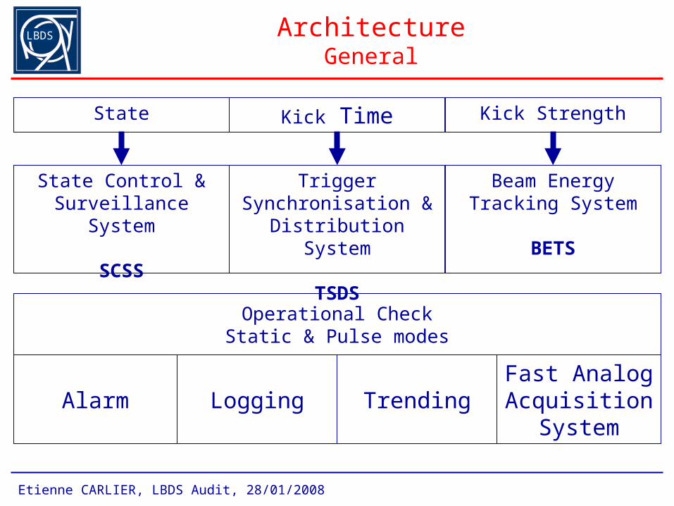
ArchitectureGeneral
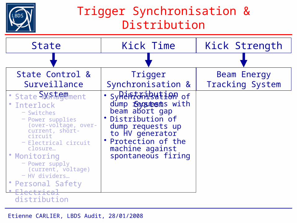
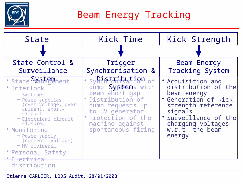
State Kick Time Kick Strength
State Control & Surveillance System
SCSS
Trigger Synchronisation & Distribution System
TSDS
Beam Energy Tracking System
BETS
Alarm Logging Trending
Operational CheckStatic & Pulse modes
Fast Analog Acquisition
System
LBDS
Etienne CARLIER, LBDS Audit, 28/01/2008
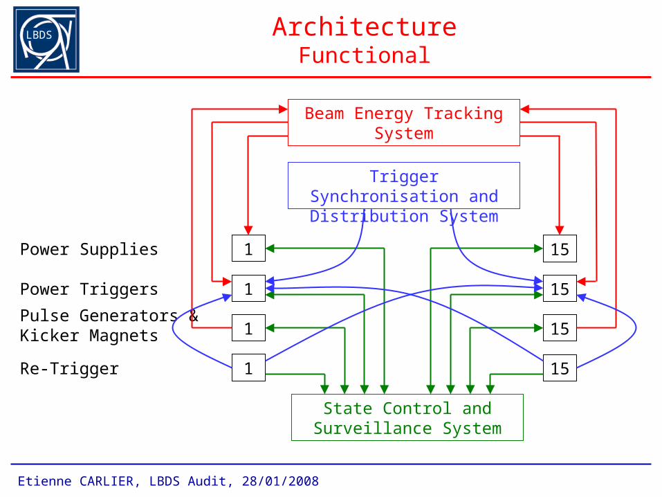
ArchitectureFunctional
Power Supplies
Power Triggers
Pulse Generators &Kicker Magnets
Re-Trigger
1
1
1
1
15
15
15
15
Beam Energy Tracking System
State Control and Surveillance System
Trigger Synchronisation and Distribution System
LBDS
Etienne CARLIER, LBDS Audit, 28/01/2008
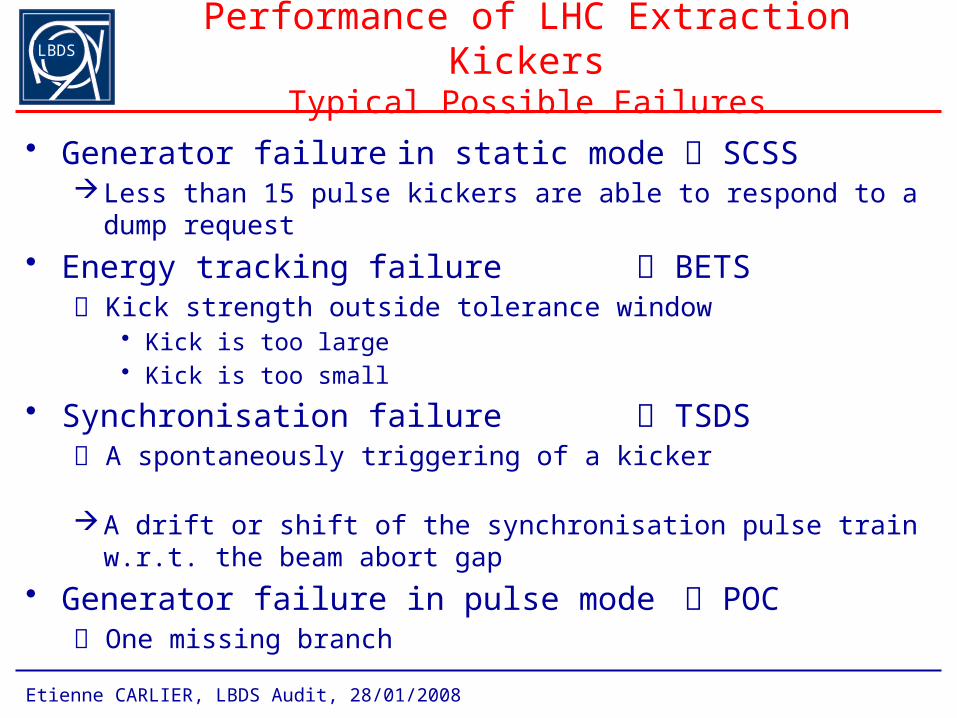
Performance of LHC Extraction KickersTypical Possible Failures
• Generator failure in static mode SCSSLess than 15 pulse kickers are able to respond to a dump request
• Energy tracking failure BETS Kick strength outside tolerance window
• Kick is too large• Kick is too small
• Synchronisation failure TSDS A spontaneously triggering of a kicker A drift or shift of the synchronisation pulse train w.r.t. the beam abort
gap
• Generator failure in pulse mode POC One missing branch
LBDS
Etienne CARLIER, LBDS Audit, 28/01/2008
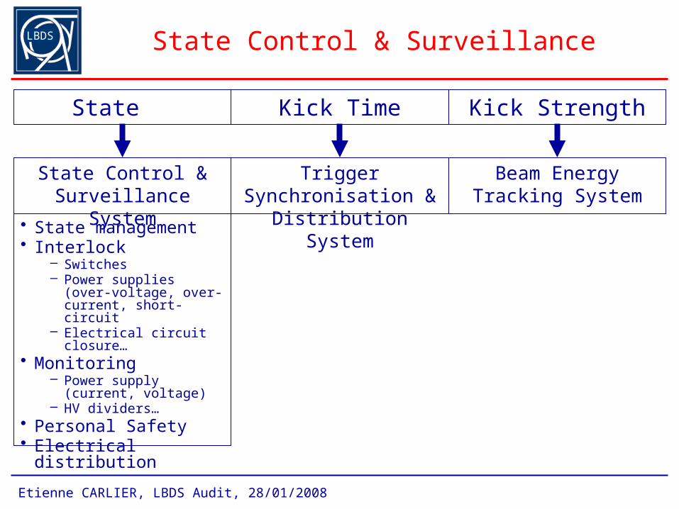
State Control & Surveillance
• State management• Interlock
– Switches– Power supplies (over-
voltage, over-current, short-circuit
– Electrical circuit closure…• Monitoring
– Power supply (current, voltage)
– HV dividers…• Personal Safety• Electrical distribution
State Kick Time Kick Strength
State Control & Surveillance System
Trigger Synchronisation & Distribution System
Beam Energy Tracking System
LBDS
Etienne CARLIER, LBDS Audit, 28/01/2008
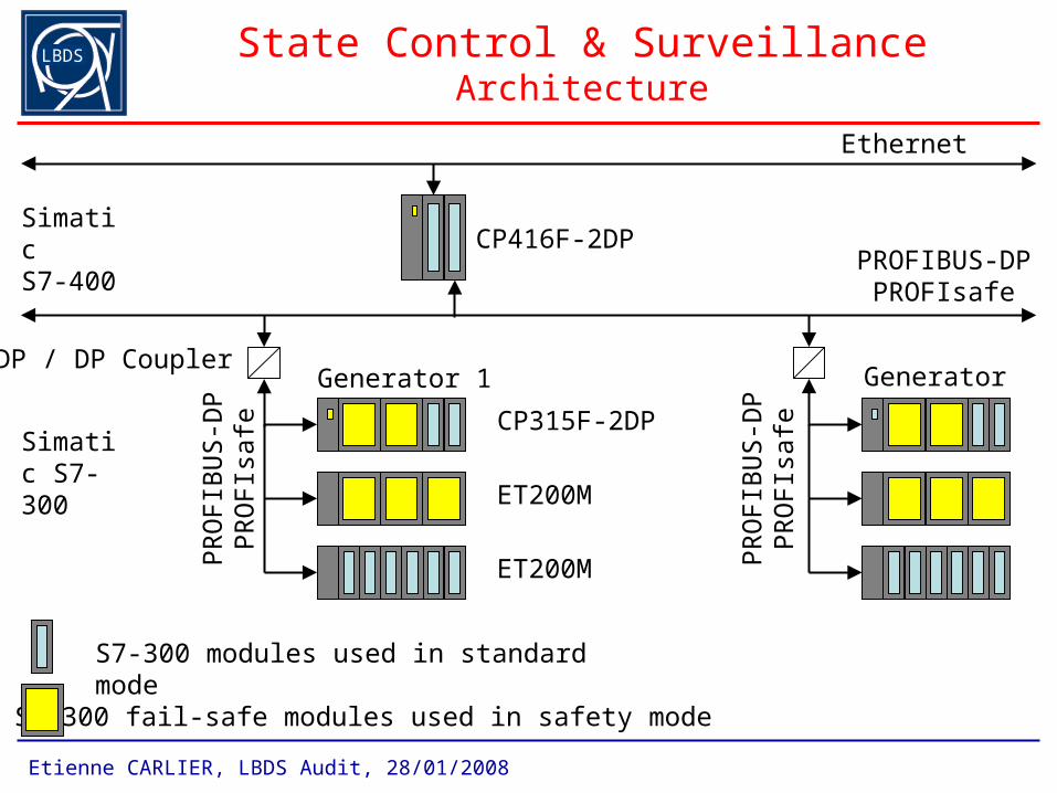
State Control & SurveillanceArchitecture
PROFIBUS-DPPROFIsafe
DP / DP Coupler
CP416F-2DP
Ethernet
SimaticS7-400
S7-300 modules used in standard mode
S7-300 fail-safe modules used in safety mode
Generator 15
PR
OF
IBU
S-D
PP
RO
FIs
afe
ET200M
ET200M
Simatic S7-300
CP315F-2DP
Generator 1
PR
OF
IBU
S-D
PP
RO
FIs
afe
LBDS
Etienne CARLIER, LBDS Audit, 28/01/2008
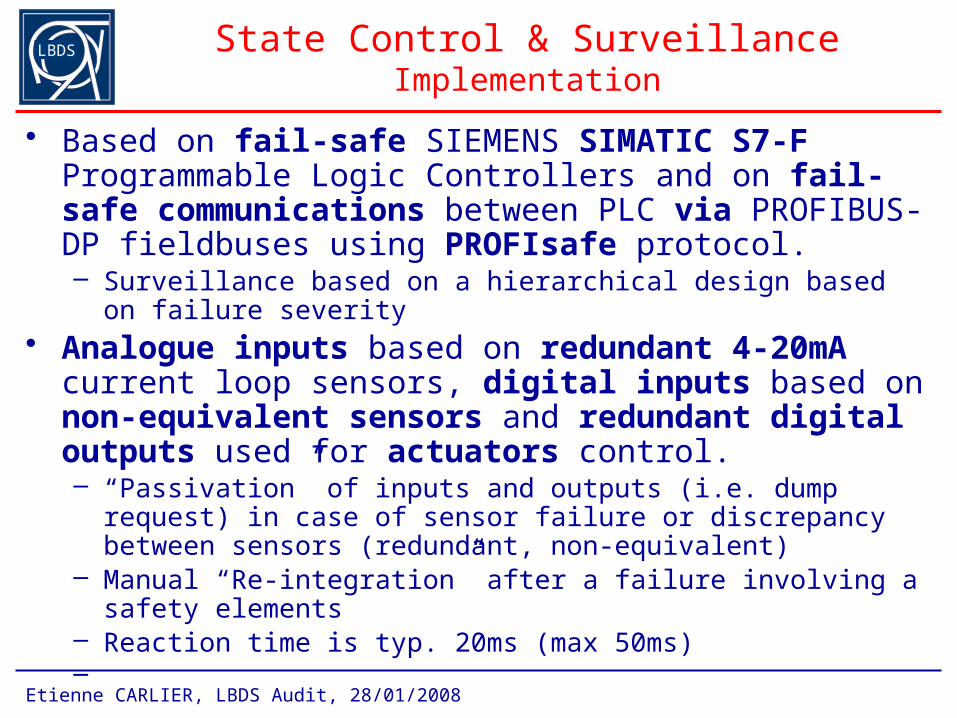
State Control & SurveillanceImplementation
• Based on fail-safe SIEMENS SIMATIC S7-F Programmable Logic Controllers and on fail-safe communications between PLC via PROFIBUS-DP fieldbuses using PROFIsafe protocol.– Surveillance based on a hierarchical design based on failure severity
• Analogue inputs based on redundant 4-20mA current loop sensors, digital inputs based on non-equivalent sensors and redundant digital outputs used for actuators control.– “Passivation” of inputs and outputs (i.e. dump request) in case of
sensor failure or discrepancy between sensors (redundant, non-equivalent)
– Manual “Re-integration” after a failure involving a safety elements– Reaction time is typ. 20ms (max 50ms) –
LBDS
Etienne CARLIER, LBDS Audit, 28/01/2008
Trigger Synchronisation & Distribution
State Kick Time Kick Strength
State Control & Surveillance System
Trigger Synchronisation & Distribution System
Beam Energy Tracking System
• Synchronisation of dump requests with beam abort gap
• Distribution of dump requests up to HV generator
• Protection of the machine against spontaneous firing
• State management• Interlock
– Switches– Power supplies (over-
voltage, over-current, short-circuit
– Electrical circuit closure…• Monitoring
– Power supply (current, voltage)
– HV dividers…• Personal Safety• Electrical distribution
LBDS
Etienne CARLIER, LBDS Audit, 28/01/2008
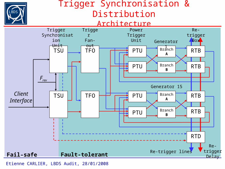
Fault-tolerantFail-safe
Trigger Synchronisation & DistributionArchitecture
Re-trigger lines
Branch A
BranchB
BranchA
BranchB
Generator 1
Generator 15
TFO
TFO
Trigger Fan-out
PTU
PTU
PTU
PTU
Power Trigger
Unit
RTB
RTB
RTB
RTB
Re-trigger Box
RTD
Re-triggerDelay
TSU
TSUClient Interface
Frev
Trigger Synchronisation
Unit
LBDS
Etienne CARLIER, LBDS Audit, 28/01/2008
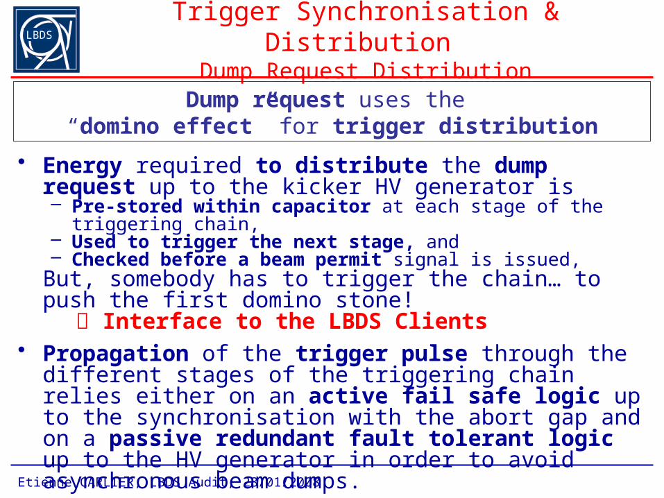
Trigger Synchronisation & Distribution Dump Request Distribution
• Energy required to distribute the dump request up to the kicker HV generator is – Pre-stored within capacitor at each stage of the triggering chain, – Used to trigger the next stage, and – Checked before a beam permit signal is issued,
But, somebody has to trigger the chain… to push the first domino stone!
Interface to the LBDS Clients• Propagation of the trigger pulse through the different
stages of the triggering chain relies either on an active fail safe logic up to the synchronisation with the abort gap and on a passive redundant fault tolerant logic up to the HV generator in order to avoid asynchronous beam dumps.
Dump request uses the “domino effect” for trigger distribution
LBDS
Etienne CARLIER, LBDS Audit, 28/01/2008
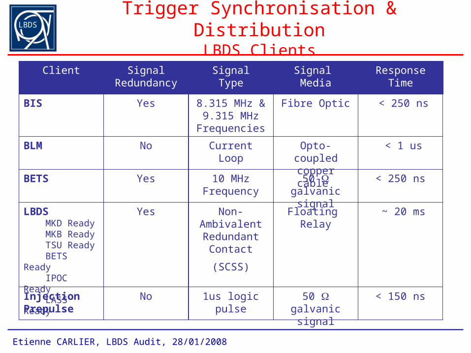
Trigger Synchronisation & DistributionLBDS Clients
BIS 8.315 MHz & 9.315 MHz
Frequencies
BLM
BETS
LBDS MKD Ready MKB Ready TSU Ready BETS Ready IPOC Ready LASS Ready
Yes
Non-Ambivalent Redundant
Contact
(SCSS)
Client
No
Yes
Yes
CurrentLoop
10 MHz Frequency
Fibre Optic < 250 ns
Opto-coupled copper cable
< 1 us
50 galvanic signal
< 250 ns
Floating Relay
~ 20 ms
SignalRedundancy
Response TimeSignal Media
SignalType
InjectionPrepulse
No 1us logic pulse 50 galvanic signal
< 150 ns
LBDS
Etienne CARLIER, LBDS Audit, 28/01/2008
Trigger Synchronisation & DistributionImplementation
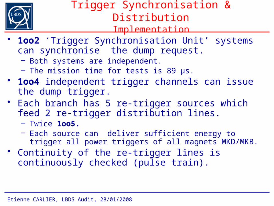
• 1oo2 ‘Trigger Synchronisation Unit’ systems can synchronise the dump request. – Both systems are independent. – The mission time for tests is 89 µs.
• 1oo4 independent trigger channels can issue the dump trigger.
• Each branch has 5 re-trigger sources which feed 2 re-trigger distribution lines. – Twice 1oo5.– Each source can deliver sufficient energy to trigger all power triggers
of all magnets MKD/MKB.• Continuity of the re-trigger lines is continuously checked
(pulse train).
LBDS
Etienne CARLIER, LBDS Audit, 28/01/2008
Beam Energy Tracking
State Kick Time Kick Strength
State Control & Surveillance System
Trigger Synchronisation & Distribution System
Beam Energy Tracking System
• Acquisition and distribution of the beam energy
• Generation of kick strength reference signals
• Surveillance of the charging voltages w.r.t. the beam energy
• Synchronisation of dump requests with beam abort gap
• Distribution of dump requests up to HV generator
• Protection of the machine against spontaneous firing
• State management• Interlock
– Switches– Power supplies (over-
voltage, over-current, short-circuit
– Electrical circuit closure…• Monitoring
– Power supply (current, voltage)
– HV dividers…• Personal Safety• Electrical distribution
LBDS
Etienne CARLIER, LBDS Audit, 28/01/2008
Beam Energy Tracking SystemFunctions
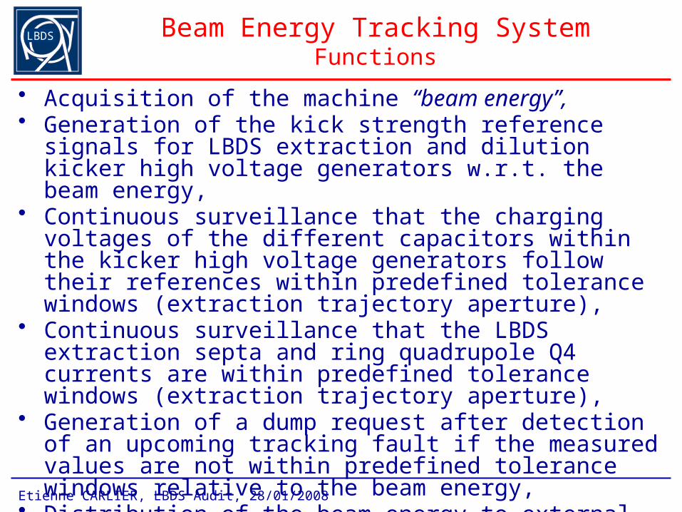
• Acquisition of the machine “beam energy”,• Generation of the kick strength reference signals for LBDS
extraction and dilution kicker high voltage generators w.r.t. the beam energy,
• Continuous surveillance that the charging voltages of the different capacitors within the kicker high voltage generators follow their references within predefined tolerance windows (extraction trajectory aperture),
• Continuous surveillance that the LBDS extraction septa and ring quadrupole Q4 currents are within predefined tolerance windows (extraction trajectory aperture),
• Generation of a dump request after detection of an upcoming tracking fault if the measured values are not within predefined tolerance windows relative to the beam energy,
• Distribution of the beam energy to external clients.
LBDS
Etienne CARLIER, LBDS Audit, 28/01/2008
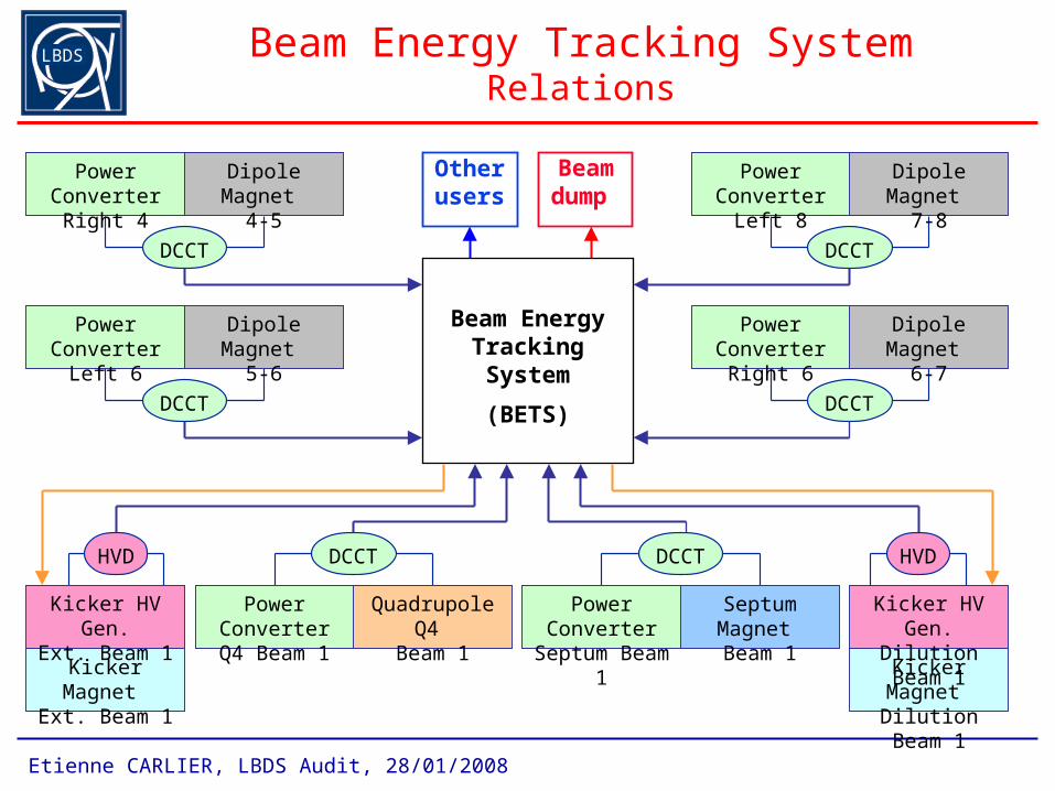
Beam Energy Tracking SystemRelations
Beamdump
Otherusers
DCCT
Dipole Magnet 4-5
Power Converter
Right 4
DCCT
Dipole Magnet 5-6
Power Converter
Left 6
DCCT
Dipole Magnet 7-8
Power Converter
Left 8
DCCT
Dipole Magnet 6-7
Power Converter
Right 6
DCCT
Septum Magnet Beam 1
Power Converter
Septum Beam 1
DCCT
Quadrupole Q4
Beam 1
Power ConverterQ4 Beam 1
HVD
Kicker Magnet Ext. Beam 1
Kicker HV Gen.Ext. Beam 1
Kicker Magnet Dilution Beam
1
Kicker HV Gen.Dilution Beam
1
Beam Energy Tracking System
(BETS)
HVD
LBDS
Etienne CARLIER, LBDS Audit, 28/01/2008
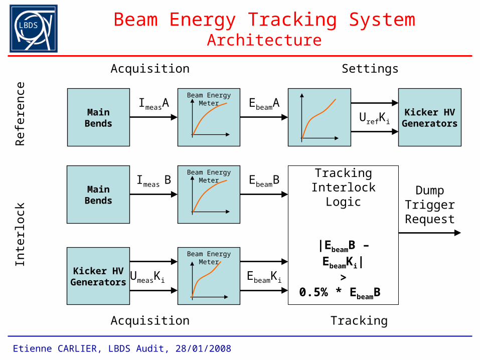
Beam Energy Tracking SystemArchitecture
MainBends
ImeasA EbeamAUrefKi
Kicker HVGenerators
Beam Energy Meter
MainBends
Imeas B EbeamB
UmeasKi Kicker HV
GeneratorsEbeamKi
Tracking Interlock Logic
|EbeamB – EbeamKi|
>0.5% * EbeamB
Dump Trigger
Request
Beam Energy Meter
Beam Energy Meter
Ref
eren
ceIn
terlo
ck
Acquisition Settings
Acquisition Tracking
LBDS
Etienne CARLIER, LBDS Audit, 28/01/2008
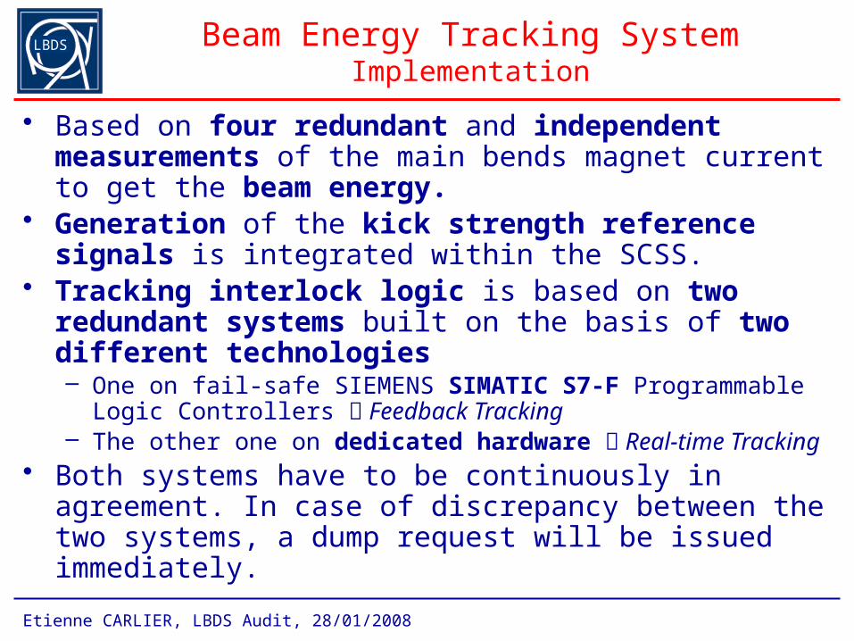
Beam Energy Tracking SystemImplementation
• Based on four redundant and independent measurements of the main bends magnet current to get the beam energy.
• Generation of the kick strength reference signals is integrated within the SCSS.
• Tracking interlock logic is based on two redundant systems built on the basis of two different technologies– One on fail-safe SIEMENS SIMATIC S7-F Programmable Logic
Controllers Feedback Tracking– The other one on dedicated hardware Real-time Tracking
• Both systems have to be continuously in agreement. In case of discrepancy between the two systems, a dump request will be issued immediately.
LBDS
Etienne CARLIER, LBDS Audit, 28/01/2008
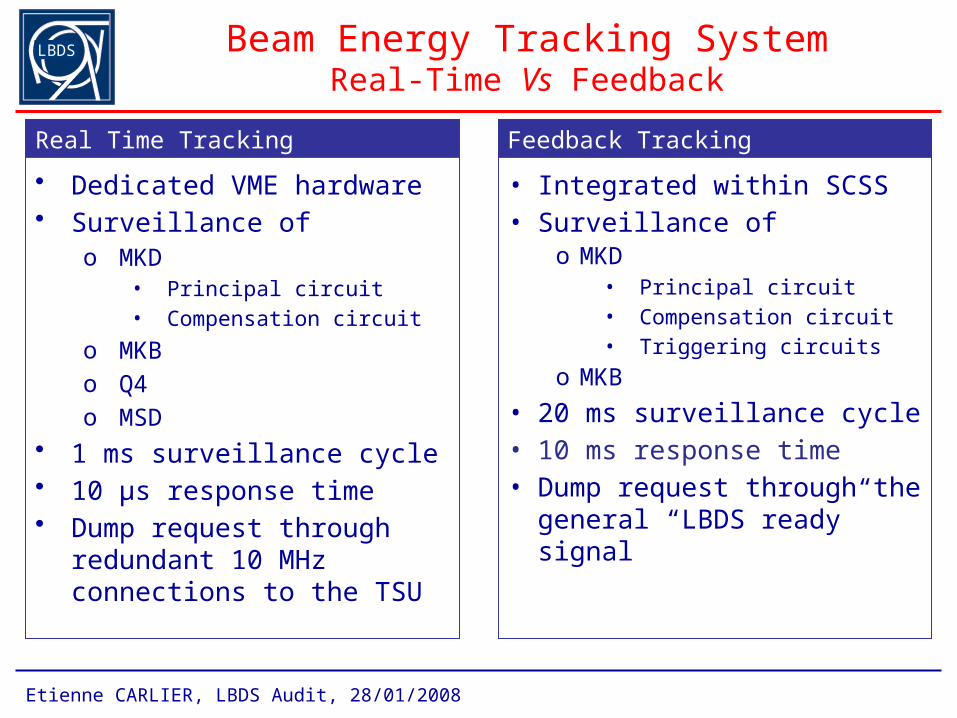
Beam Energy Tracking SystemReal-Time Vs Feedback
• Dedicated VME hardware• Surveillance of
o MKD• Principal circuit• Compensation circuit
o MKB o Q4o MSD
• 1 ms surveillance cycle• 10 µs response time• Dump request through
redundant 10 MHz connections to the TSU
• Integrated within SCSS • Surveillance of
o MKD• Principal circuit• Compensation circuit• Triggering circuits
o MKB
• 20 ms surveillance cycle• 10 ms response time• Dump request through the
general “LBDS ready” signal
Real Time Tracking Feedback Tracking
LBDS
Etienne CARLIER, LBDS Audit, 28/01/2008
Post-Operational Check
• Post-Operationnal analysis is the only way to verify the correct execution of the last dump action.
• Despite a perfectly dumped beam, it remains possible that damage has been caused to one or more components of the dump system during the previous dump action (e.g. the solid state switches).
• The beam dump system will be declared ready for the next mission if, and only if, it can be expected that all the hardware, including all the redundant components, will respond correctly to the next dump request.
LBDS
Etienne CARLIER, LBDS Audit, 28/01/2008
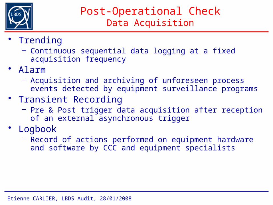
Post-Operational CheckData Acquisition
• Trending– Continuous sequential data logging at a fixed acquisition frequency
• Alarm– Acquisition and archiving of unforeseen process events detected by
equipment surveillance programs • Transient Recording
– Pre & Post trigger data acquisition after reception of an external asynchronous trigger
• Logbook– Record of actions performed on equipment hardware and software by
CCC and equipment specialists
LBDS
Etienne CARLIER, LBDS Audit, 28/01/2008
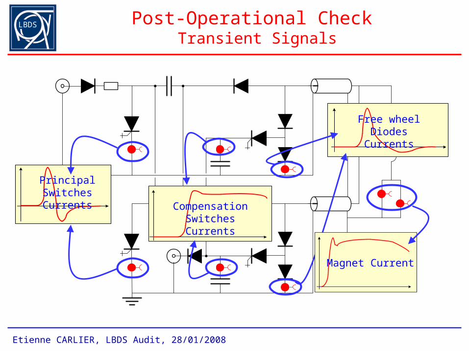
Post-Operational Check Transient Signals
Principal SwitchesCurrents
Compensation SwitchesCurrents
Free wheel DiodesCurrents
Magnet Current
LBDS
Etienne CARLIER, LBDS Audit, 28/01/2008
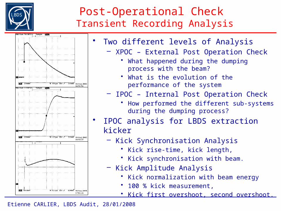
Post-Operational Check Transient Recording Analysis
• Two different levels of Analysis– XPOC – External Post Operation Check
• What happened during the dumping process with the beam?
• What is the evolution of the performance of the system
– IPOC – Internal Post Operation Check• How performed the different sub-systems during the
dumping process?
• IPOC analysis for LBDS extraction kicker– Kick Synchronisation Analysis
• Kick rise-time, kick length, • Kick synchronisation with beam.
– Kick Amplitude Analysis• Kick normalization with beam energy• 100 % kick measurement, • Kick first overshoot, second overshoot.
LBDS
Etienne CARLIER, LBDS Audit, 28/01/2008
Post-Operational Check Implementation
• High precision acquisition and analysis of the 15 magnet current pulse shapes will be performed after each dump action. – 2 different types of acquisition sensors: Pearson PU (passive) and Rogowski
PU (active)• The acquisition system is based on two CompactPCI crates running
SCL4 and housing:– NI-PXI 5122 digitizers with 14 bit resolution and 100 MS/s sampling rate for
the kick strength & kick synchronisation surveillance and monitoring• Acquisition and verification of the current in the different branches of
the generator in order to identify the faulty circuit will be available in a second phase (prototype available)– Principal circuit– Compensation circuit– Freewheel circuit