kinematics of machinery - srividyaengg.ac.in · kinematics of machinery me6401 ... part -a 1. what...
TRANSCRIPT
Kinematics of Machinery ME6401
Dept. of Mechanical Engg, Sri Vidya College of Engg & Tech, Virudhunagar – 626005. Page 1
UNIT – 2 KINEMATICS OF LINKAGE MECHANISMS
PART -A
1. What are the important concepts in velocity analysis?
1. The absolute velocity of any point on a mechanism is the velocity of that point with
reference to ground.
2. Relative velocity describes how one point on a mechanism moves relative to another
point on the mechanism.
2. Define Instantaneous centre.
Instantaneous centre of a moving body may be defined as that centre which goes
on changing from one instant to another.
3. How to represent the direction of linear velocity of any point on a link with respect
to another point on the same link?
The direction of linear velocity of any point on a link with respect to another
point on the same link is perpendicular to the line joining the points.
4. Define Kennedy’s theorem.
The Kennedy’s theorem states that if three bodies move relatively to each other,
they have three instantaneous centers and lie on a straight line.
5. Define displacement.
It may be defined as the distance moved by a body with respect to a fixed
certain fixed point. When there is no displacement in a body it is said to be at rest and
when it is being displaced, it is said to be in motion.
6. What are the types of motions?
1. Rectilinear motion.
2. Curvilinear motion.
3. Circular motion.
7. What are the methods for determining the velocity of a body?
Important methods for determining the velocity of a body are:
1. Graphical method: i) Relative velocity method
ii) Instantaneous centre method
2. Analytical method.
Kinematics of Machinery ME6401
Dept. of Mechanical Engg, Sri Vidya College of Engg & Tech, Virudhunagar – 626005. Page 2
8. Define velocity.
Velocity may be defined as the rate of change of displacement of a body with
respect to the time. Since the velocity has both magnitude and direction, therefore it
is a vector quantity
9. Define speed.
Speed may be defined as the rate of change of linear displacement of a body
with respect to the time. Since the speed is irrespective of its direction, therefore it is a
scalar quantity.
10. What is deceleration?
The negative acceleration is also known as deceleration or retardation. 11. Define Acceleration.
The rate of change of velocity with respect to time is known as acceleration. 12. Define coincident points.
When a point on one link is sliding along another rotating link, then the point is
known as coincident point.
13. Define centrode.
The locus of all instantaneous centre’s (i.e., I1, I2,…) is known as centrode.
14. Define Axode.
The locus of all instantaneous axis is known as axode. 15. Define Body centrode.
The locus of all instantaneous centre relative to the body itself is called the body
centrode.
16. What is relative pole, with respect to velocity analysis?
A pole of move link is the centre of its rotation with respect to fixed link.
However, if the rotation of the link is considered relative to another moving link, the
pole is known as relative pole.
17. Name the mechanism in which corolis component of acceleration is taken into accont.
Crank and slotted mechanism
Withworth quick return
Scotch yoke
Kinematics of Machinery ME6401
Dept. of Mechanical Engg, Sri Vidya College of Engg & Tech, Virudhunagar – 626005. Page 3
UNIT – 2 KINEMATICS OF LINKAGE MECHANISMS
PART - B
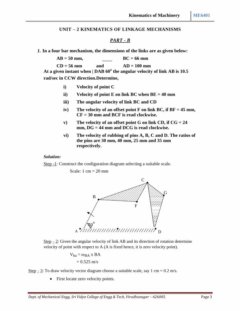
1. In a four bar mechanism, the dimensions of the links are as given below:
AB = 50 mm, BC = 66 mm
CD = 56 mm and AD = 100 mm
At a given instant when | DAB 60o the angular velocity of link AB is 10.5
rad/sec in CCW direction.Determine,
i) Velocity of point C
ii) Velocity of point E on link BC when BE = 40 mm
iii) The angular velocity of link BC and CD
iv) The velocity of an offset point F on link BC, if BF = 45 mm, CF = 30 mm and BCF is read clockwise.
v) The velocity of an offset point G on link CD, if CG = 24
mm, DG = 44 mm and DCG is read clockwise.
vi) The velocity of rubbing of pins A, B, C and D. The ratios of the pins are 30 mm, 40 mm, 25 mm and 35 mm respectively.
Solution:
Step -1: Construct the configuration diagram selecting a suitable scale.
Scale: 1 cm = 20 mm
C
G B
F
60o
A D
Step – 2: Given the angular velocity of link AB and its direction of rotation determine
velocity of point with respect to A (A is fixed hence, it is zero velocity point).
Vba = BA x BA
= 0.525 m/s
Step – 3: To draw velocity vector diagram choose a suitable scale, say 1 cm = 0.2 m/s.
First locate zero velocity points.

Kinematics of Machinery ME6401
Dept. of Mechanical Engg, Sri Vidya College of Engg & Tech, Virudhunagar – 626005. Page 4
Draw a line r to link AB in the direction of rotation of link AB (CCW)
equal to 0.525 m/s.
b
Vba = 0.525 m/s
e, g
a, d
f C Ved
From b draw a line r to BC and from d. Draw d line
r to CD to interest at C.
Vcb is given vector bc Vbc = 0.44 m/s
Vcd is given vector dc Vcd = 0.39 m/s
Step – 4:
be BE = be = 0.24 m/s
bc BC
Join e on velocity vector diagram to zero velocity points a, d / vector de = Ve
= 0.415 m/s.
Step 5: To determine angular velocity of links BC and CD, we know Vbc and Vcd.
Vbc =ω BC x BC 6.6 r / s . (cw)
Similarly, Vcd = ωCD x CD
ωCD = 6.96 r / s (CCW)
Step – 6: To determine velocity of an offset point F
Vf = 0.495 m/s.
Step – 7: To determine velocity of an offset point G.
Vg = dg 0.305 m / s
Step – 8: To determine rubbing velocity at pins
Rubbing velocity at pin A will be Vpa = ab x r of pin A
Vpa = 10.5 x 0.03 = 0.315 m/s
Rubbing velocity at pin B will be Vpb = (ab + cb) x rpb of point at B.
[ab CCW and cbCW]
Vpb = (10.5 + 6.6) x 0.04 = 0.684 m/s.
Rubbing velocity at point C will be = 6.96 x 0.035 = 0.244 m/s

Kinematics of Machinery ME6401
Dept. of Mechanical Engg, Sri Vidya College of Engg & Tech, Virudhunagar – 626005. Page 5
2. In a slider crank mechanism the crank is 200 mm long and rotates at 40 rad/sec in a
CCW direction. The length of the connecting rod is 800 mm. When the crank turns
through 60o from Inner-dead centre.
Determine,
i) The velocity of the slider
ii) Velocity of point E located at a distance of 200 mm on the
connecting rod extended.
iii) The position and velocity of point F on the connecting rod having the least absolute velocity.
iv) The angular velocity of connecting rod.
v) The velocity of rubbing of pins of crank shaft, crank and cross head
having pins diameters 80,60 and 100 mm respectively
Solution:
Step 1: Draw the configuration diagram by selecting a suitable scale.
E A
F
45o
B
O G
Va = Woa x OA : Va = 40 x 0.2
Va = 8 m/s
e
a Scale: 1 cm = 2 m/s
f
b o, g
Vba=4.8 m/sec
Ve = ge =8.4 m/sec
To mark the position of F on link AB. Find BF by using the relation.
BF = 200 mm Angular velocity of connecting rod = 6 rad / sec
VPcrank pin = (ab + oa) rcrank pin= (6 +8)0.06 =0.84 m/secVP cross head = ab x rcross head = 6 x 0.1 = 0.6 m/sec

Kinematics of Machinery ME6401
Dept. of Mechanical Engg, Sri Vidya College of Engg & Tech, Virudhunagar – 626005. Page 6
3. A quick return mechanism of crank and slotted lever type shaping machine is shown in Fig. the dimensions of various links are as follows. O1O2 = 800 mm, O1B = 300 mm, O2D = 1300 mm and DR = 400 mm. The crank O1B makes an angle of 45
o with the vertical and relates at 40 rpm in the CCW
direction. Find:
i) Velocity of the Ram R, velocity of cutting tool, and ii) Angular velocity of link O2D.
Solution:
Step 1: Draw the configuration diagram.
R
R D
200 Tool D
B on orank, O, B B
O1
C
C on O2D 45
o
2
O1
O2
O2
Step 2: Determine velocity of point B.
Vb = O1B x O1B = O1B = 4.18 rad/ sec
Vb = 4.18 x 0.3 = 1.254 m/sec
Step 3: Draw velocity vector diagram.
Choose a suitable scale 1 cm = 0.3 m/sec
b d
c
r
O1O2
Kinematics of Machinery ME6401
Dept. of Mechanical Engg, Sri Vidya College of Engg & Tech, Virudhunagar – 626005. Page 7
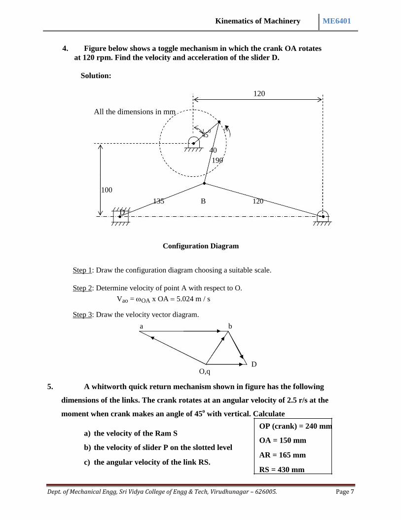
4. Figure below shows a toggle mechanism in which the crank OA rotates
at 120 rpm. Find the velocity and acceleration of the slider D.
Solution:
120
All the dimensions in mm
45o A
40
190
100
135 B 120
D
Configuration Diagram
Step 1: Draw the configuration diagram choosing a suitable scale.
Step 2: Determine velocity of point A with respect to O.
Vao = OA x OA5.024 m / s
Step 3: Draw the velocity vector diagram.
a b
D O,q
5. A whitworth quick return mechanism shown in figure has the following
dimensions of the links. The crank rotates at an angular velocity of 2.5 r/s at the
moment when crank makes an angle of 45o with vertical. Calculate
OP (crank) = 240 mm
a) the velocity of the Ram S OA = 150 mm
b) the velocity of slider P on the slotted level AR = 165 mm
c) the angular velocity of the link RS. RS = 430 mm

Kinematics of Machinery ME6401
Dept. of Mechanical Engg, Sri Vidya College of Engg & Tech, Virudhunagar – 626005. Page 8
Solution:
Step 1: To draw configuration diagram to a suitable scale.
R
S A
O P on slider Q on
45o BA
B
Configuration Diagram
Step 2: To determine the absolute velocity of point P.
VP = OP x OP = 0.6 m/s
Step 3: Draw the velocity vector diagram by choosing a suitable scale.
P
0.6 m q
S
O, a, g
r
Velocity vector diagram
Kinematics of Machinery ME6401
Dept. of Mechanical Engg, Sri Vidya College of Engg & Tech, Virudhunagar – 626005. Page 9
·
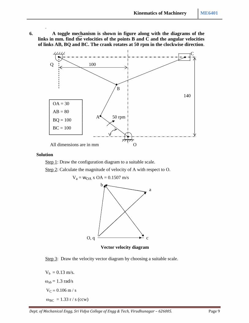
6. A toggle mechanism is shown in figure along with the diagrams of the
links in mm. find the velocities of the points B and C and the angular velocities of links AB, BQ and BC. The crank rotates at 50 rpm in the clockwise direction.
C
Q 100
B
140
OA = 30
AB = 80
A 50 rpm BQ = 100
BC = 100
All dimensions are in mm O
Solution
Step 1: Draw the configuration diagram to a suitable scale.
Step 2: Calculate the magnitude of velocity of A with respect to O.
Va = wOA x OA = 0.1507 m/s
b a
O, q c
Vector velocity diagram
Step 3: Draw the velocity vector diagram by choosing a suitable scale.
Vb = 0.13 m/s.
ab = 1.3 rad/s
VC 0.106 m / s
BC = 1.33 r / s (ccw)

Kinematics of Machinery ME6401
Dept. of Mechanical Engg, Sri Vidya College of Engg & Tech, Virudhunagar – 626005. Page 10
7. For the mechanism shown in figure link 2 rotates at constant angular velocity of 1 rad/sec construct the velocity polygon and determine.
i) Velocity of point D.
ii) Angular velocity of link BD.
iii) Velocity of slider C.
Solution:
Step 1: Draw configuration diagram.
6 D
O6
5
102 mm A
3 B
45o
O2
O2 = 50.8 mm
AB = 102 mm
BD = 102 mm
DO6 = 102 mm
AC = 203 mm
C 4
Step 2: Determine velocity of A with respect to O2.
Vb = 2 x O2A
Vb = 1 x 50.8 = 50.8 mm/sec.
Step 3: Draw the velocity vector diagram, locate zero velocity points O2O6.
a d
Vd Udb
b
C
Vd = O6 d = 32 mm/sec

Kinematics of Machinery ME6401
Dept. of Mechanical Engg, Sri Vidya College of Engg & Tech, Virudhunagar – 626005. Page 11
8. A slider crank mechanism has lengths of crank and connecting rod equal to 200 mm and 200 mm respectively locate all the instantaneous centers of the mechanism for the position of the crank when it has turned through 30
o from
IOC. Also find velocity of slider and angular velocity of connecting rod if crank rotates at 40 rad/sec. Solution:
Step 1: Draw configuration diagram to a suitable scale.
Step 2: Determine the number of links in the mechanism and find number of instantaneous centers.
N = n 1n = 6
2
I13
I24
A 3 2
200 800 I23
B
I12 30o
4
O 1 1 I12
I14 to I14 to
Step 3: Identify instantaneous centers.
Suit it is a 4-bar link the resulting figure will be a square.
1 I12 2
I24
1 2 3 4
I12 I23
I34
I41 I23 OR I13 I24
I13 I14
4 I34 3
Locate fixed and permanent instantaneous centers. To locate neither fixed nor permanent instantaneous centers use Kennedy’s three centers theorem.
Step 4: Velocity of different points.
Va = 2 AI12 = 40 x 0.2 = 8 m/s
Vb = 3 x BI13 = Velocity of slider.

Kinematics of Machinery ME6401
Dept. of Mechanical Engg, Sri Vidya College of Engg & Tech, Virudhunagar – 626005. Page 12
9. A four bar mechanisms has links AB = 300 mm, BC = CD = 360 mm and AD =
600 mm. Angle | BAD 60o . Crank AB rotates in C direction at a speed of
100 rpm. Locate all the instantaneous centers and determine the angular
velocity of link BC.
Solution:
Step 1: Draw the configuration diagram to a suitable scale.
N= 6
Step 2: Identify the IC’s by circular method or book keeping method.
1 I12 2
I12 1 2 3 4
I14
I23
I12 I23 I34
OR
I13
I13 I24
I14
4 I34 3
Step 4: Locate all the visible IC’s and locate other IC’s by Kennedy’s theorem.
I13
3
C
I34
B
I23 4
2
I24 I12 1 I14 D BI13
Va = 8 m/s.

Kinematics of Machinery ME6401
Dept. of Mechanical Engg, Sri Vidya College of Engg & Tech, Virudhunagar – 626005. Page 13
10. For a mechanism in figure crank OA rotates at 100 rpm clockwise using I.C. method determine the linear velocities of points B, C, D and angular velocities of links AB, BC and CD.
OA = 20 cm AB = 150 cm BC = 60 cm
CD = 50 cm BE = 40 cm OE = 135cm
A
C D 5
2 3
6
1
30o
E
10 mm
O
4
B
Va = OA x OA
Va = 2 x 100 x 0.2 2.1 m / s
60 n = 6 links
N= 15
1 2 3 4 5 6 5
12 23 34 45 56 4
3 13 24 35 46
2
14 25 36
1 15 26 ---
15 16
---
I16 @ I16 @ I16 @
I13
I45
I23
5 6
1
2
3
I14 I56
I12
I34
I15
Link 3 I13
A 3 B

Kinematics of Machinery ME6401
Dept. of Mechanical Engg, Sri Vidya College of Engg & Tech, Virudhunagar – 626005. Page 14
Va = 3AI13
3 = Va 2.5 rad / sec
AI13
Vb = 3 x BI13 = 2.675 m/s
Link 4 C
I14
4
B
Also Vb = 4 x BI14
4 = Vb 6.37 rad / sec
BI
14
VC = 4 x CI14 = 1.273 m/s
Link 5 C 5 D
VC = 5 x CI15
5 = VC 1.72 rad / sec
AI15
Vd = 5 x DI15 = 0.826 m/s
I15
Answers
Vb = 2.675 m/s VC = 1.273 m/s Vd = 0.826 m/s
ab = 2.5 rad/sec
bc = 6.37 rad/sec
cd = 1.72 rad/sec
·