kinematics support for design and simulation of ... · kinematics support for design and simulation...
TRANSCRIPT
Kinematics Support for Design and Simulation of Mechatronic Systems
Rajarishi Sinha I , Cluistiaan J.J. Paredisl.2 and Pradeep K. Khoslal.2
1 Institute for Complex Engineered Systems, Carnegie Mellon University, Pittsburgh, PA 15213, USA 2Department of Electrical and Computer Engineering, Carnegie Mellon University, Pittsburgh, PA 15213, USA
Abstract: We present a framework that combines both/orm (CAD models) and behavior (simulation models) of mechatronic system components into component objects. By composing these component objects, designers automatically create a virtual prototype of the system they are designing. The framework verifies and maintains the consistency between the representations of the form, function, and behavior of the virtual prototype. This virtual prototype, in tum, can provide immediate feedback about design decisions by evaluating whether the functional requirements are met in simulation. When the designer makes a change to one aspect of the representation, our framework automatically updates all other aspects impacted by this change and reports inconsistencies. Inconsistencies occur when the kinematic behavior of the device does not match the form, or the kinematic behavior does not match the currently specified functional description. Continuous feedback of this nature shortens the design-simulate cycle for product design. To achieve composition of behavioral models, we use a port-based modeling paradigm in which component interactions are defined by connections between ports. Component objects and component interactions together form the system model of the device. Simulation models for the components are defined in VHDL-AMS and are solved with a commercial solver.
Key words: CAD, Port-based modeling, VHDL-AMS, Simulation, Mechatronics, Multibody mechanics, Design consistency
184 Rajarishi Sinha, Christiaan J.J. Paredis, and Pradeep K. Khosla
1. INTRODUCTION AND MOTIVATION
The realization of new mechatronic devices is characterized by ever shortening times to market, along with increasing customer demand for improved quality. In this business environment, it is important for the designer to be able to simulate the behavior of the current state of the design. As the design evolves, its form, behavior, and intended function should be consistent with each other. In addition, information about the behavior should be automatically obtained from the CAD model of the device. Simulation of the behavior will catch inconsistencies early in the design process, reducing the need for physical proto typing and decreasing the time to market. To accomplish this goal, we are developing a software environment for simulation-based design, in which modeling and design tools are tightly integrated.
Consider the following scenario. A designer begins the design process by defining the desired kinematic function of a device. She then converts the desired function into an intended behavior described by a simple ball-andstick model. As the design evolves, she introduces information about local geometry at the joint contact, then the complete geometry, and finally the inertial properties. At each stage, the representation is enriched and a simulation can be generated with the available information. The kinematic representation is combined with inertial properties to generate automatically a dynamics behavioral simulation. If inertial properties are not available, then a pure form-based kinematic behavioral simulation is generated. If form (i.e. geometry and materials) is also not available, then a functional simulation is generated. The behavioral simulation results are compared with the desired function description. Inconsistencies are reported back to the designer.
This scenario illustrates the need for tools that support all the following aspects of the design process:
• Hierarchical representation of the form, function, and behavior of the product incorporating kinematics.
• Automatic generation of such a representation from geometry. • Consistency checking of the representation. • Automatic generation of a behavioral simulation.
We provide a framework that supports each of these aspects. We use the port-based modeling paradigm to describe the device. In this approach, each body or joint is represented as a component that interacts with other components in the system through interfaces consisting of ports. Each component encapsulates the form of the physical object (body or joint), and the behavioral model of the object that relates the port variables of the component with each other.
Kinematics Support for Design and Simulation 185
This framework is integrated with CAD, by providing algorithms that automatically derive the behavioral models from the geometry of the device. VHDL-AMS (IEEE, 1999) is used to define the behavioral models of each of the components in the device. A commercial VHDL-AMS simulator is used to evaluate the models. We apply our framework to the mechanical design process of a 2-DOF missile seeker.
2. RELATED WORK
The related literature can be classified into the following categories: product representation for design, algorithmic modeling of multi-body systems, modeling of conserved-energy systems, and multi-domain modeling in VHDL-AMS.
Pahl and Beitz (1996) describe the geometry, the task and the actions taken to realize the task as three aspects of the representation of an artifact. Shooter et al. (2000) describe design as a process of transformation of information. They propose a framework to formalize the semantics of design information and to standardize the exchange of such information. Our framework maintains consistency between these three aspects during the transformation of design information.
Baraff (1989) used algorithmic methods to simulate the mechanical dynamics of multi-body systems with constraints. Such an approach involves setting up the ordinary differential equations (ODEs) that govern the dynamics of the multi-body system, and solving them using variable step numerical methods. Our framework extends this approach by allowing for the composition of models, or hierarchical systems, and for the easy definition of joint constraints.
There exist several modeling paradigms for describing multi-domain systems. Karnopp et al. (1990) model conserved energy-flow systems using bond graphs. Linear graph techniques have been used to model rigid body dynamics (McPhee et al., 1996). Diaz-Calderon et al. (1999) have extended linear graph theory to include n-terminal elements and software components. They have created a software architecture based on composition of simulation models by connecting components through interfaces. Our framework is based on this approach.
VHDL-AMS is the IEEE standard that extends the VHDL language by adding the ability to handle continuous time signals, including non-electrical domains. Since this is a recent standard, little work has been done in realizing the potential of VHDL-AMS to implement multi-energy domain simulation. Most of the mechanics-related results come from the MEMS area
186 Rajarishi Sinha, Christiaan J.J. Paredis, and Pradeep K. Khosla
(Romanowicz, 1998; Bielefeld et al., 1995). Our implementation uses VHDL-AMS for behavioral modeling.
3. FRAMEWORK FOR MECHANICAL COMPONENT MODELING
3.1 The Port-Based Modeling Paradigm
We view systems as structures of inter-connected elements interacting with the environment. Elements in the system interact with each other through ports (Diaz-Calderon et al., 1999). Ports are points on the boundary of the system where energy is exchanged between the system and the environment. Each interaction point has a port, and each port belongs to a particular energy domain.
Energy flow through a port is described by an across variable and a through variable. An across variable represents a value measured between a global reference and the port, such as a velocity, while a through variable represents a value measured through the element, such as a force. A connection between ports results in algebraic constraints between the port variables that are described by Kirchoffian network laws.
Because each interaction point requires a separate port, our modeling paradigm is limited to interactions that can be modeled as being localized at a finite number of points on the boundary of the system. The paradigm further supports hierarchical model structure with any number of levels in the hierarchy (Diaz-Calderon et al., 1999). The hierarchy must be terminated by primitive components that are described by declarative equations. These equations establish differential-algebraic relationships between the variables of the ports of the component.
3.2 Port-Based Modeling of Mechanical Systems
Rigid bodies in contact with each other are constrained in their motion by the nature of the contact (Figure 1). The mechanical behavior of each rigid body is completely described by the position and orientation of the body (across variables), and the forces and torques acting on the body (through variables).
Since a rigid mass has only one set of across and through variables, it has a single port. The constraint between a pair of rigid masses is captured in a joint component that has two ports.

Kinematics Support for Design and Simulation
Figure J. A joint constraint captures the contact interaction between two rigid bodies A and B. CA and CB are the positions of the centers of gravity and PI and P2 are the contact points.
187
Two rigid body models are never connected directly to each other; they are connected through a joint component. When the port on a mass component is connected to a port on a joint component, a node is implicitly created, and the two ports in question are connected to this node (Figure 2). In the mechanical domain, the Kirchoff network laws become:
(1)
and
(2)
where are the port variables for body i = A,B. Pi is the across through
position vector of body i, Rj is the quaternion describing the orientation of
body i, F; is the external force acting on body i, and t j is the external
torque acting on the body i.
In general, the internals of a component can be a behavioral model, or a sub-system consisting of interconnected components, allowing for composable and hierarchical models. The behavioral model of a component establishes relationships among the port variables in the form of ODEs or algebraic equations (AEs).
3.3 Rigid Body Component Model
A rigid body component is described by a point mass at the center of gravity and an inertia tensor that captures the mass distribution. All positions and orientations are expressed relative to a global frame of reference. The
188 Rajarishi Sinha, Christiaan J.J. Paredis, and Pradeep K. Khosla
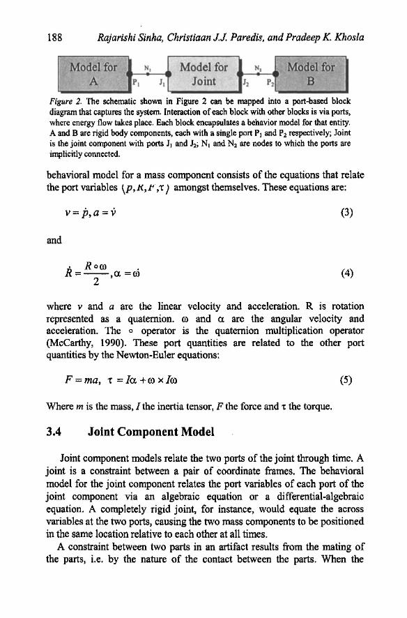
Model for N, Model for N. Model for A PI II Joint Iz Pz B
Figure 2. The schematic shown in Figure 2 can be mapped into a port-based block diagram that captures the system Interaction of each block with other blocks is via ports, where energy flow takes place. Each block encapsulates a behavior model for that entity. A and B are rigid body components, each with a single port PI and Pz respectively; Joint is the joint component with ports JI and Jz; NI and Nz are nodes to which the ports are implicitly connected.
behavioral model for a mass component consists of the equations that relate the port variables \P,K,J<,t) amongst themselves. These equations are:
and
V= p,a = v
. Roro . R=-- a. =ro
2 '
(3)
(4)
where v and a are the linear velocity and acceleration. R is rotation represented as a quaternion. co and ex. are the angular velocity and acceleration. The 0 operator is the quaternion multiplication operator (McCarthy, 1990). These port quantities are related to the other port quantities by the Newton-Euler equations:
F = ma, t = la. +ro x lro (5)
Where m is the mass, I the inertia tensor, F the force and t the torque.
3.4 Joint Component Model
Joint component models relate the two ports of the joint through time. A joint is a constraint between a pair of coordinate frames. The behavioral model for the joint component relates the port variables of each port of the joint component via an algebraic equation or a differential-algebraic equation. A completely rigid joint, for instance, would equate the across variables at the two ports, causing the two mass components to be positioned in the same location relative to each other at all times.
A constraint between two parts in an artifact results from the mating of the parts, i.e. by the nature of the contact between the parts. When the

Kinematics Support for Design and Simulation 189
contact is a surface to surface contact, a lower kinematic pair is created (Figure 3). Currently we support the lower pairs of joints.
A revolute joint has a single degree of freedom-a pure rotation about an axis. Written in the homogeneous transform notation, we have:
(6)
where RK te) is the rotation transform about the rotation axis A = LlCx ' ICy ,1C:z 1- The transform' '1 F2 relates the transforms FJ and F2 of the two masses respectively by constraining them to rotate about each other about a specified axis, A, and by a specified angle, e.
A Prismatic Joint has a single degree of freedom, namely pure translation along an axis:
(7)
where TK td) is the translation transform along a general translation axis A = LICX,lCy,IC:zJ.
A spherical joint has three rotational degrees of freedom about a point, called the center. This is expressed by the constraint:
(8)
where ptF) is the origin of the frame F. The orientation is unconstrained, realizing a spherical joint constraint.
Figure 3. Revolute, prismatic and spherical joints.
4. DERIVATION OF THE BEHAVIORAL MODEL FROM GEOMETRY
Composable simulations are based on the concept of component objects that combine form and behavior. By composing component objects into systems, a designer simultaneously designs and models new artifacts. The previous section introduced a modular modeling paradigm that supports such

190 Rajarishi Sinha, Christiaan J.J. Paredis, and Pradeep K. Khosla
composition. In this section, we focus on guaranteeing that these behavioral models are consistent with the corresponding form descriptions as represented by a CAD model.
We distinguish between two different types of behavioral models: models representing physical components, and models representing interactions between components. Examples of physical components are motors, screws, shafts, or controllers. Their component objects contain a description of both form and behavior. Interaction models, on the other hand, do not have any associated form. Yet, their model parameters can be extracted from the form of the two interacting components. Examples of interaction models are lower pairs that result from mechanical contact, contact resistance in an electrical switch, etc.
4.1 Form and Behavior of Component Objects
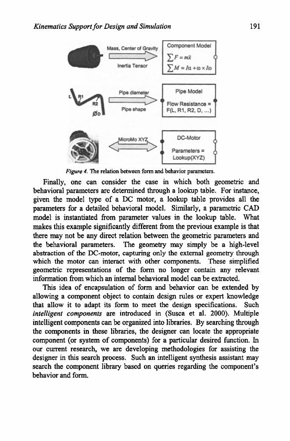
A component object contains a description of the form of the component as well as a model describing its behavior. Ideally, behavioral models are generated from the form automatically. This requires combining information about geometry and materials with knowledge of the physical phenomena occurring in the component. Creating such models automatically is difficult in the general case, but can be achieved for certain classes or families of components. For example, the mechanical behavior of the set of rigid bodies with homogeneous material properties is completely defined by the mass and inertial parameters, as is shown in Figure 4. These rigid bodies are so common in mechatronic systems, that it makes sense to develop a procedure that computes the inertial parameters from the density and the geometry of the component, as defined in a CAD model. As a result, the behavior models of homogeneous rigid bodies can be derived automatically for any material and arbitrary geometry.
Besides rigid bodies, we can automatically generate behavioral models for parametric CAD models. In a parametric CAD model, the designer establishes relationships between certain geometric dimensions or parameters. As a result, the form is completely defined by a limited set of characteristic parameters or features. Behavioral models also contain parameters, which, in tum, can be related to the CAD parameters. These relations can be simple, as in the rigid body example, or can be quite complicated, as for a hydraulic pipe. As is illustrated in Figure 4, the flow resistance of the pipe depends on its length, diameter, and bending radii. Although these dimensions may not be defined explicitly in the CAD model, they can be extracted through parametric relations captured as procedures (Bettig et al. 2000; Shah and Mantyla 1995).
Kinematics Support for Design and Simulation
Mass, Center of Gravity
I ::> Inertia Tensor
Pipe diameter
L 1 R2 L---I :> Pipe shape
!liD
Component Model
LF=nU ( LM = la +m )(/m
Pipe Model
Flow Reslstance = 4 F(L, R1 , R2, D, ... )
DC-Motor (
Parameters = ( Lookup(XYZ)
Figure 4. The relation between form and behavior parameters.
191
Finally, one can consider the case in which both geometric and behavioral parameters are determined through a lookup table. For instance, given the model type of a DC motor, a lookup table provides all the parameters for a detailed behavioral model. Similarly, a parametric CAD model is instantiated from parameter values in the lookup table. What makes this example significantly different from the previous example is that there may not be any direct relation between the geometric parameters and the behavioral parameters. The geometry may simply be a high-level abstraction of the DC-motor, capturing only the external geometry through which the motor can interact with other components. These simplified geometric representations of the form no longer contain any relevant information from which an internal behavioral model can be extracted.
This idea of encapsulation of form and behavior can be extended by allowing a component object to contain design rules or expert lmowledge that allow it to adapt its form to meet the design specifications. Such intelligent components are introduced in (Susca et al. 2000). Multiple intelligent components can be organized into libraries. By searching through the components in these libraries, the designer can locate the appropriate component (or system of components) for a particular desired function. In our current research, we are developing methodologies for assisting the designer in this search process. Such an intelligent synthesis assistant may search the component library based on queries regarding the component's behavior and form.

192 Rajarishi Sinha, Christiaan J.J. Paredis, and Pradeep K. Khosla
---
Physical Object A
------Electrical Domain (default interaction)
across,. = across, Lthrough, = 0
Physical ObJectB
'---. --. ---Mechanical Domain (complex interaction)
Joint Model. Gear Model. Friction.
Figure 5. Interaction between system components.
4.2 Form and Behavior of Component Interactions
In addition to the behavioral models of component objects, systems include models describing the interactions between component objects. For each pair of interacting component objects, there is an interaction model that relates the port variables of the two objects to each other.
Any interaction in any energy domain requires an interaction model. However, for the electrical domain, the interaction model is usually very simple. An electrical connection between two components is modeled sufficiently accurately by constraining the voltage at the two connecting ports to be equal and the current through them to sum to zero. Because this interaction model is so common, we allow it to be omitted in our modeling paradigm, as is shown in Figure 5. In the mechanical domain, the equivalent default model is rarely appropriate. Even when connecting two components rigidly, their reference frame is usually in a different location so that a model representing the coordinate transformation is needed.
Besides rigid connections, other common mechanical interaction models are the lower pair kinematic constraints. Algorithms have been developed to predict the instantaneous degrees of freedom from the CAD models of parts composed of polygonal planar faces (Mattikalli et aI., 1994). However, these algorithms handle only parts with planar faces while most engineering devices have curved parts. When curved parts are approximated as piecewise planar parts, it is possible to overlook degrees of freedom in the device, due to erroneous collisions.
In our previous work (Sinha et aI., in press), we have shown that when rigid bodies are in contact, the kinematic degrees of freedom can be automatically derived from the nature of the contact. When two rigid parts share a surface-surface contact, every contact point is subject to a nonpenetration condition. This condition requires that the instantaneous velocity
Kinematics Support for Design and Simulation 193
of separation of the two bodies does not have a component in the direction opposite to that of the surface normal at that point. We write this condition as a linear algebraic constraint of the form:
(9)
where v and ro are the relative translational and angular velocities between the two bodies, r is the position of the point and ii is the normal at a point of contact on the surface of contact. Imposing the constraint Equation (9) at every point on the contact surface is equivalent to imposing the constraint at a finite number of points on the convex hull of the surface. Therefore, a finite number of linear constraints are imposed simultaneously for every contact surface in the device. This analysis results in a linear relationship of the form:
(10)
where J assembly is the description of the surface-surface contacts in the system and v is the generalized velocity vector for the system. In this work, the Jassembly matrix is used to verify that the behavioral model is consistent with the CAD model of the system. Additionally, this matrix can be used to verify that a desired degree of freedom as specified in the functional description actually exists in the behavioral model. The properties of the Jassembly matrix determine the choice of kinematic joint for this pair of rigid bodies, and the parameters for this joint. For example, the basis vectors of the nullspace of the Jassembly matrix represent the contact-preserving degrees of freedom.
Our method can infer behavior from devices with (incomplete) curved geometry, while at the same time resolving global (i.e. multi-part) constraint interactions. Linear algebra-based constraint models are derived directly from CAD models, and then converted into articulation representations suitable for assembly planning and motion simulation. Our underlying algorithms support automatic extraction of the kinematic behavioral model from the geometry. The model can be queried about candidate degrees of freedom to verify whether the actual and desired degrees of freedom match. The algorithms propagate global interactions throughout the model, and support a wide variety of geometric features that are encountered in a CAD environment. They are implemented in C++ using the ACIS solid modeler and use MATLAB for numerical computations.

194 Rajarishi Sinha, Christiaan J.J. Paredis, and Pradeep K. Khosla
4.3 VHDL-AMS Behavioral Models from Kinematics and Dynamics Parameters
We view mechanical system design as an iterative process of configuration of components. Component objects include both the geometry and the behavior and are stored as XML within our system. A component object is completely instantiated when both the geometry and behavior are specified and synchronized with each other. At simulation time, the XML representation of the component objects and component interactions are translated into the VHDL-AMS description of the system. A change in the form, function or behavioral aspects of the virtual prototype results in a regeneration of the VHDL-AMS description.
The environment is an agent-based Java implementation, with a product model based on our product representation. This model is queried and updated by agents and by the designer through OUIs, while iterating towards a final device design. A simulation of the current state of the design is created by automatically converting the product representation (stored as
. XML) into a VHDL-AMS specification of the system. A commercial VHDL-AMS solver is used to evaluate the models over time.
5. DESIGN SCENARIO
We now examine the design process for a missile seeker. We assume that some portions of the design will be reused, at least conceptually, from a previously designed missile seeker.
The seeker is a device with 2 rotational degrees of freedom. It carries a camera as a payload that scans a 2-dimensional area for a particular target. The seeker incorporates the articulated mechanism that realizes these degrees of freedom, as well as DC motors and controllers. The design process of the complete mechatronic device involves refining the design in all the energy domains. For this work, we will only consider the kinematics and mechanical dynamics of the design.
5.1 Design Initiation
A previously designed missile seeker is retrieved from the database. It is a device that can point the camera payload to any location along a line. This seeker has one rotational degree of freedom, realized by a revolute joint mounted in the housing. The new seeker must have 2 degrees of freedom to scan a 2-dimensional workspace. Therefore, the designer decides that the

Kinematics Support for Design and Simulation 195
legacy design can be modified to add another rotational degree of freedom that is coupled to the existing degree of freedom.
5.2 Iterative Design Refinement
The designer constructs a ball and stick kinematic model for the new seeker by decomposing the function into two rotational OOFs. The new design includes a second rotational OOF coupled with the existing OOF (Figure 6).
Subassembly 1
I R-DOF 1 R-DOF
Figure 6. Kinematic model and structural model of a portion of the device.
This kinematic model is realized in geometry by adding mating surfaces. To realize the degrees of freedom, the joints are positioned in space with their axes aligned with the desired OOF. A structural model of the design is created with blocks representing components in the design (Figure 6).
The joints are grouped with geometry to form structural subassemblies as shown in Figure 7. Surface contacts are placed in space such that the specified rotational degrees of freedom meet the functional requirement.
When the designer creates a new geometrical entity in the CAD system, a corresponding mass component object is instantiated in the behavioral system description. Our algorithms automatically extract the parameters for this component object. Joint component interactions are automatically computed and instantiated from the contacts between mass components. For this seeker, two motors are created, each with a revolute joint between the stator and the rotor (Figure 7). These motors and their potentiometers are placed at the spatial locations of the contact.
The designer verifies that the instantiated geometry matches the desired kinematic behavior by performing a contact analysis on the fly. The analysis results in a behavioral model of the current state of the design. The behavioral model is incorporated into VHDL-AMS entities. A simulation is generated from the VHDL-AMS models of the mass and joint components (component objects and component interactions) to verify that the intended function is achieved.

196 Rajarishi Sinha, Christiaan J.J. Paredis, and Pradeep K. Khosla
Pitch Axis
_-+--CI Yaw Axis
Figure 7. Instantiation of geometry at the spatial locations of the contacts realizes the degrees of freedom.
5.3 Final Design and Dynamics Simulation
At this stage, the geometry of the payload is introduced into the design. In addition, a gimbal is introduced to couple the degrees of freedom while preserving symmetry in the geometry.
Our framework compiles the CAD models to extract lumped mass component parameters. These values are used to instantiate the corresponding mass components in the VHDL-AMS system representation. Contact analysis is performed to propagate global multi-part constraints and verifies that the instantiated geometry still matches the desired behavioral description.
Complete geometry is now available (Figure 8). Mass component objects and joint component interactions are completely instantiated in the VHDLAMS system description. The VHDL-AMS solver collects the declarative differential and algebraic equations (DAEs) for the system and solves them through time (Figure 8).
8. Complete geometry and dynamics simulation of the 2·DOF seeker.
The mechanics design process is now complete. The VHDL-AMS system description can be augmented with descriptions of the electrical behavior of the motors, models for the controllers, etc. Now more advanced analyses such as finite element analysis, thermal analysis and manufacturability analysis can be performed.
Kinematics Support for Design and Simulation 197
6. SUMMARY
We present a hierarchical framework to model mechanical components to support composable simulation. The framework is based on component objects that combine descriptions of both form and behavior of system components. The framework verifies and maintains consistency between the form, function, and behavior of mechatronic components, as all three aspects evolve during the design process. As more design information becomes available during the design process, behavioral models for rigid bodies and joints are automatically created, and parameters are automatically derived. Mass and joint components are instantiated in VHDL-AMS, and a commercial solver is used to simulate the system model of the mechatronic device.
The design process for a 2-DOF missile seeker is used to demonstrate the applicability of simulation. By observing the process of design, and examining the use of simulation during this process, we conclude the following: a tightly coupled iterative cycle between design and simulation can save time and money by catching errors early in the design process; design quality may improve because of incremental simulation and continuous synchronization of the form, function, and behavior of the device; automatic derivation of kinematic behavioral models from form allows for automatic instantiation and update of joint components; compilation of CAD models to extract parameters allows for automatic instantiation and updating of mass components; the port-based modeling paradigm permits hierarchical reusable models; and the use of VHDL-AMS allows for a single design/simulation framework to capture multi-domain behavioral and structural models.
ACKNOWLEDGMENTS
The authors would like to acknowledge Antonio Diaz-Calderon for his input and advice. We also acknowledge the comments provided by the reviewers; they improved the quality of the manuscript. This research was funded in part by DARPA under contract ONR # N00014-96-1-0854, by the National Institute of Standards and Technology, by the National Science Foundation under grant # CISE/l15IKDI 98 73005, by the Pennsylvania Infrastructure Technology Alliance, and by the Institute for Complex Engineered Systems at Carnegie Mellon University.
198 Rajarishi Sinha, Christiaan J.J. Paredis, and Pradeep K. Khosla
REFERENCES
Baraff, D. (1989). Analytical methods for dynamic simulation of non-penetrating rigid bodies, Computer Graphics, Vol. 23, No.3, pp. 223-232.
Bettig, B., Summers, J. D., and Shah, J. J. (2000). Geometric Examplars: a Bridge between CAD and AI, The Fourth IFIP Working Group 5.2 Workshop on Knowledge Intensive CAD (K/C-4), Parma, Italy, 57-71.
Bielefeld, J., Pelz, G., and Zimmer, G. (1995). Analog Hardware Description Languages for Modeling and Simulation of Micro systems and Mechatronics, Proceedings of the Conference on Mechatronics and Robotics, Stuttgart, 1995, pp. 85-92.
Diaz-Calderon, A., Paredis, C.J.J., and Khosla, P.K. (1999). A Composable Simulation Environment for Mechatronic Systems, Proceedings of the 1999 SCS European Simulation Symposium, October 26-28,1999, Erlangen, Germany.
IEEE. (1999). 1076.1-1999 IEEE Standard VHDL Analog and Mixed-Signal Extensions. Kamopp, D. C., Margolis, D. L., and Rosenberg, R.C. (1990). System dynamics: A unified
approach. John Wiley & Sons, Inc. New York, NY. Mattikalli, R., Baraff, D., and Khosla, P.K. (1994). Finding All Gravitationally Stable
Orientations of Assemblies, Proceedings of the IEEE International Conference of Robotics and Automation, May 1994, San Diego, CA, pp. 251-257.
McCarthy, l M. (1990). An Introduction to Theoretical Kinematics, The MIT Press, Cambridge, MA, USA.
McPhee, l l, Ishac, M. G., and G. C. Andrews. (1996). Wittenburg'S formulation of multibody dynamics equations from a graph-theoretic perspective, Mechanism and Machine Theory, Vol. 31, pp. 202-213.
Pahi, G., and Beitz, W. (1996). Engineering Design: A Systematic Approach, 2nd Edition, Springer-Verlag, London, U.K., ISBN 3-540-19917-9.
Romanowicz, B.F. (1998). Methodology for the Modeling and Simulation of Microsystems, Kluwer Academic Publishers.
Shah, J. J., and Mantyla, M. (1995). Parametric and Feature-Based CAD/CAM: Concepts, Techniques, Applications, John Wiley & Sons, New York, NY.
Shooter, S. B., Keirouz, W., Szykman, S., and Fenves, S.J. (2000). A Model for the Flow of Design Information, Proceedings of the 2000 ASME DeSign Engineering Technical Conferences (12th International Conference on Design Theory and Methodology), September 2000, Baltimore, MD.
Sinha, R., Gupta, S.K., Paredis, c.J.J., and Khosla, P.K. (in press). Extracting Articulation Models from CAD Models of Parts with Curved Surfaces, ASME Journal of Mechanical Design.
Susca, L., Mandorli, F., and Rizzi, C. (2000). How to Represent "Intelligent" Components in a Product Model: a Practical Example, The Fourth IFIP Working Group 5.2 Workshop on Knowledge Intensive CAD (K/C-4), Parma, Italy, 197-208.