kitchenaid magnetic drive torrent blender service/repair ... · 1 literature parts 11 w10625865...
TRANSCRIPT

W11036951
KitchenAid
® Magnetic Drive Torrent™ Blender
Service/Repair Manual
Intended for Professional Technician Only
(Includes International model)
5KSB5080 (AU, EU, UK), 5KSB5085 (AU)
Domestic Model KSB5010

- 2 -
KitchenAid®
Magnetic Drive Torrent™ Blender
Service/Repair Manual
Intended for Professional Technician Only © 2015 KitchenAid
®
Covers Models: Domestic Models – KSB5010AC (Almond Cream), KSB5010CA (Candy Apple), KSB5010ER (Empire Red), KSB5010MS (Medallion Silver),
KSB5010QG (Liquid Graphite), KSB5010SR (Sugar Pearl), KSB5010SZ (Slate), KSB5010OB (Onyx Black)
EU Models – 5KSB5080EAC (Almond Cream), 5KSB5080EBK (Imperial Black), 5KSB5080ECA (Candy Apple), 5KSB5080EER (Empire Red), 5KSB5080EFP (Frosted Pearl), 5KSB5080EMS (Medallion silver), 5KSB5080EOB (Onyx Black)
UK Models – 5KSB5080BAC (Almond Cream), 5KSB5080BBK (Imperial Black), 5KSB5080BCA (Candy Apple), 5KSB5080BER (Empire Red), 5KSB5080BFP (Frosted Pearl), 5KSB5080BMS (Medallion silver), 5KSB5080BOB (Onyx Black)
AU Models – 5KSB5080AER (Empire Red), 5KSB5080BOB (Onyx Black), 5KSB5085ACA (Candy Apple), 5KSB5085BFP (Frosted Pearl)
Table of Contents
Subject Page(s)
Introduction 2
Attachment Parts with parts list (exploded view) 3
Unit Parts (exploded view) 4
Unit Parts List 5
Important Service Workplace Safety Recommendations 6
Service Environment 6
Personal Protection 6
Electrical Considerations 6
Important Safeguards 7
List of Tools Required 7
Electrical Requirements 7
Testing the Product 7
Service Procedures: 8
Component Access (Upper Housing Removal and Surround access) 8
Electronics Access (Hall Sensor, Control board, Motor Lead and Speaker) 11
Surround and Power Cord Removal 13
Lower Housing Disassembly (belt removal and replacement) 15
Lower Housing reassembly 18
Installing the Cord and Surround Housing 19
Installing the Electronics (Speaker, Control Board, Hall Sensor and Insulation) 21
Surround/Upper Cover and Safety Interlock Switch replacement 22
Upper Housing reassembly 23
Appendix Subject Page(s)
A Tools Required for Torrent Blender Service 25
B Troubleshooting Quick Reference Guide 26
C Torrent Blender Screw Torques 27
Introduction
All KitchenAid®
Products are well designed. Normally they will give continual use year after year without service attention.
Records have been maintained to determine and correct, through improved design, any troubles that might possibly develop. An effort has been made in preparation of this manual to cover them all.

- 3 -
Attachment Parts List
Illus. No. Part No. Description
Illus. No. Part No. Description
1 W10690049 Lid, Blender
3
W10630713 Funnel, Blender
2 W10627688 Jar Assembly
4 W10667686 Cap Assembly

- 4 -
International
Models Only

- 5 -
Unit Parts List Illus. No. Part No. Description Illus. No. Part No. Description
1 Literature Parts 11 W10625865 Base, Blender
W10683173 Use & Care Guide, European/Britain
12 W10001200 Screw
W10729916 Use & Care Guide, Australian 13 Foot, Blender
W10679580 Use & Care Guide, domestic W10524701 Black
2 W10667412 Collar, Blender 14 Cover, Upper Housing
3 Housing, Upper W10718042 Almond Creme
W10718041 Almond Creme W10708608 Imperial Black
W10708607 Imperial Black W10707892 Candy Apple
W10707891 Candy Apple W10718036 Empire Red
W10718034 Empire Red W10707886 Frosted Pearl
W10707885 Frosted Pearl W10707882 Medallion Silver W10707881 Medallion Silver W10707878 Onyx Black
W10707877 Onyx Black 15 W10691804 W10625893
230v. Control Board Assembly 120v. Control Board Assembly
4 W10625896 User Interface Assembly 16 W10769702 Lever Assembly (Includes Boot)
5 3400617 Screw 17 Housing, Surround
6 W10584177 Screw W10718040 Almond Creme
7 W10709017 Seal, Upper Blender W10708606 Imperial Black
8 Power Cord W10707889 Candy Apple
W10643544 European W10718033 Empire Red
W10730060 Australian W10707884 Frosted Pearl
W10720322 Britain W10707880 Medallion Silver
W10643543 Domestic (120v.) W10707876 Onyx Black
9 3400814 Screw 18 W10568405 Assembly, Speaker
10 Housing Assembly, Lower (Includes Motor and Belt)
19 W10643552 Wire, Ground (International Models only)
W10776358 Almond Cream (AC), 230v. 20 W10625877 Housing, Front
W10776362 Imperial Black (BK), 230v. 21 W10276642 Screw
W10776356 Candy Apple (CA), 230v. 22 W10634065 Switch Assembly, Interlock
W10776357 Empire Red (ER), 230v. 23 W10768470 Bumper Assembly
W10776359 Frosted Pearl (FP), 230v. 24 Trim Band
W10776360 Medallion Silver (MS), 230v. W10712546 European/Britain
W10776363 Onyx Black (OB), 230v. W10729919 Australian
W10776355 Slate (SZ), 120v. W10629023 domestic
W10776354 Liquid Graphite (QG), 120v. 25 W10625890 Belt, Drive
W10776353 Onyx Black (OB), 120v. 26 W10728670 Insulation, Sound (Front Housing)
W10776352 Sugar Pearl (SR), 120v. 27 W10728666 Insulation,
W10776351 Frosted Pearl (FP), 120v.
W10776350 Candy Apple (CA), 120v.

- 6 -
ELECTRICAL CONSIDERATIONS
The workplace for servicing the product should have properly grounded AC outlets that adhere to all Local Electrical Codes that are applicable at the time of repair.
The power cord should always be inspected first before plugging the unit into an energized power outlet.
Do Not run the unit if the power cord is damaged - replace it.
ESD (Electro Static Discharge) protection should be provided when servicing the electronic components.
All disassembly and assembly procedures discussed in this manual should be conducted with the unit disconnected from the AC power source.
Do Not leave the unit unattended while running it for inspection or for any other checks.
Do Not remove any parts from the unit while it is running.
Always unplug the appliance immediately after concluding all electrical tests.
IMPORTANT SERVICE WORKPLACE SAFETY RECOMMENDATIONS
The purpose of this manual is to familiarize the professional house wares service technician with the techniques required to repair the following:
Domestic KitchenAid®
Torrent™ Blender
Model KSB5010
International KitchenAid®
Torrent™ Blender
Model 5KSB5080
SERVICE ENVIRONMENT
The following Safety Guidelines should be adhered to when servicing this product.
The workplace should be dry and sanitary at all times and all units should be inspected for cleanliness before any work is started.
Visually inspect the unit requiring service in a well illuminated area.
A mild, non-abrasive dishwashing soap solution and clean damp towel can be used to wash any unit requiring attention.

- 7 -
The hands of the service technician should be clean at all times during the service procedure.
PERSONAL PROTECTION
The Service Technician should wear Protective Eyewear at all times when conducting a repair on the unit.
Loose fitting sweaters, shirt sleeves or bracelets should not be worn while servicing any product with rotating parts.
IMPORTANT SAFEGUARDS
Ensure the KitchenAid®
service technician is aware of the operating safeguards recommended to the customer:
1. Read all instructions in the Service Guide before attempting any service to the unit.
2. Close supervision is necessary when any food processing product is used by or near children.
3. The product has been UL listed for household and commercial use.
4. To protect against electrical shock, do not immerse cord, plugs, or the unit housing in water or other liquid.
5. Do not operate any product with a damaged cord or plug or after the product has malfunctioned or has been damaged in any manner.
6. Unplug the unit from the outlet before cleaning.
7. Do not let the cord hang over the edge of a table or counter or touch hot surfaces.
8. Do not use an extension cord.
9. The use of accessories not recommended by
KitchenAid®
may result in fire, shock, or injury to persons.
10. Do not use the product outdoors.
11. Do not place the product on or near a hot gas or electric burner or on a heated oven.
12. Do not use the product for other than its intended use.
13. Do not use the product without the proper safety devices in place while in operation.
14. Do not bypass any of the safety features on the unit while attempting to service the unit.
15. Do not clean the unit or it’s attachments with harsh cleaners, steel wool pads or other abrasive material.
LIST OF REQUIRED TOOLS
The following tools are necessary to service the
KitchenAid®
Torrent Blender.
#R2 Square Bit Screwdriver
Phillips Screwdriver Set
Flat Blade Screwdriver Set
NOTE: Power drivers are not recommended for
servicing KitchenAid®
Portable Appliances.
Needle Nose Pliers (to help manipulate wires)
Side (or Diagonal) Cutters (to remove wire ties)
Volt/Ohm Meter
The following equipment will greatly assist the technician
in servicing KitchenAid®
Portable Appliances:
Low pressure compressed air to remove debris from components.
Clean rags or shop towels
Cushion the service area to keep from scratching the product or damaging the controls. A clean shop towel or other folded cloth will usually work well for this purpose.
ELECTRICAL REQUIREMENTS
This product is designed for use with 120 VAC, 60 Hz (240 VAC, 50 Hz International) only. It has a grounded plug and should not be modified in any way. Do not use an extension cord or an adapter with this product.
A power supply cord of appropriate length is provided to reduce the risks resulting from becoming entangled in or tripping over a longer cord. If the power supply cord is too short, have a qualified electrician or service technician install an outlet near the area where the product will be used.
TESTING THE PRODUCT
The service technician will have to test the performance of the product to identify and diagnose any problem.

- 8 -
Normal electrical testing techniques, using a volt/ohm meter, are sufficient to test the products electrical components.
NOTE: Refer to the Troubleshooting Quick Reference Guide (Appendix B) in the back of this manual while performing any test.
Review any documentation accompanying the faulty appliance.
Perform a ground continuity test and a dielectric withstand (HiPot) test prior to plugging the product into an electrical outlet.
Prior to disassembling the product, plug it into an electrical outlet and perform a function test. Test the switches, speed selections, etc. for proper operation and to troubleshoot for the problem.
After troubleshooting, use the SERVICE PROCEDURES to replace any faulty component.
SERVICE PROCEDURES
This manual is written as a step-by-step guide to
disassemble and reassemble the KitchenAid®
Torrent™ Blender to gain access to the systems within the unit that are in need of repair. For models covered in this manual, refer to the index page.
Most of the KitchenAid®
Torrent™ Blender components are contained within the blender’s motor surround housing. Perform the Component Access Procedure (below) to gain access to the blender components.
NOTE: When removing self-tapping screws from any plastic or metal housing, the filings created will be scattered onto adjoining components. Prior to performing any reassembly procedure, make sure to remove all the filings using clean rags, low-pressure compressed air, etc.
Use of the Troubleshooting Quick Reference Guide (Appendix B) will aid in determining what steps are necessary for repairing the unit. Not all steps will be needed for some of the repairs so it is important to consult the Troubleshooting Quick Reference Guide first.
Appendix D lists all of the screw torques required for proper reassembly of the unit.
Component Access (Upper Housing Removal and Surround access)
Most replacement procedures will require access to the inside of the product. To gain access to the components:
1. Unplug the power cord.
2. Remove the 8-32 X .540 screw on the back of the blender that secures the upper housing to the surround (Fig. 1).
3. With the ingredient cap, collar, jar and lid removed, turn the food processor upside-down on a cushioned surface (a soft towel is recommended).
4. Remove the (2) remaining 8-32 X .540 screws from the underside of the upper housing assembly (Fig. 2).
Fig. 1) Remove the screw at the back of the upper housing
Fig. 2) Remove the (2) screws that secure the upper cover to the upper housing

- 9 -
5. While holding the upper cover to the upper housing with one hand, upright the blender on the work surface (Fig. 3).
Fig. 3) Hold the upper cover to the upper housing when up righting the unit
6. Remove the upper housing by lifting it from the unit and unplugging the UI from the electronic control circuit board squeezing the tab on the plug while pulling it from the socket (Fig. 4).
Fig. 4) Squeeze the tab on the UI wire harness plug to remove it from the electronic control circuit board
7. The collar can be removed from the upper cover by removing the (3) 8-16 x .562 screws that secure it in place (Fig. 5).
Fig. 5) Remove the 3 screws holding the collar to the housing
8. Remove the UI from the upper housing by depressing the (4) plastic tabs that secure it in place with a small flat blade screwdriver while applying outward pressure to the back of the UI assembly (Fig. 6).
Fig. 6) Release the tabs on the UI to remove it from the upper housing
Fig. 7) Apply pressure to the back of the UI to remove it from the upper housing

- 10 -
9. Remove the (4) 6-32 x .250 screws that secure the safety interlock switches to the upper cover.
10. Unplug the safety interlock switch assembly from the electronic control circuit board and set it aside on the workbench with the screws (Fig. 8).
Fig. 8) Remove the 4 screws that secure the safety interlock switches.
11. Unplug the speaker wire harness from the electronic control circuit board (Fig. 9).
Fig. 9) Unplug the speaker wire harness from the electronic control circuit board
12. Using a large flat blade screwdriver, remove the jar bumper located down low on the inside of the unit at the front plastic housing by unscrewing it counter-clockwise (Fig. 10).
Fig. 10) Remove the jar bumper from the inside of the front plastic housing by turning out counter-clockwise
13. Remove the (4) 8-32 x .325 screws that secure the upper cover to the blender housing surround (Fig. 11).
Fig. 11) Remove the 4 screws that secure the upper cover.
14. Using a small flat blade screwdriver and being careful not to scratch the surround housing, gently pry the plastic front housing front from the surround sliding it and the upper cover free from the rest of the blender body (Figs. 12 & 13).

- 11 -
Fig. 12) Use a small flat blade screwdriver to release the front (plastic) housing and upper cover.
Fig. 13) slide the upper cover and front (plastic) housing out from the unit.
15. The upper cover can be removed from the front housing by loosening the (2) 8-16 x .562 screws that secure it to the front housing. Once the screws have been loosened, the upper cover should easily lift off the front housing (Fig. 14).
Note: There is no need to fully remove the (2) screws as loosening them is enough to allow the removal of the upper cover.
Fig. 14) Loosen the two screws on the back of the front plastic cover to release the upper cover.
16. Remove the upper blender seal (rubber) from the upper cover (Fig. 15) and replace if it is damaged.
Fig. 15) Remove and replace the upper blender seal if it is damaged.

- 12 -
Electronics Access (Hall Sensor, Control Board, Motor lead and Speaker)
17. Remove the insulation from the unit by maneuvering the motor wires through the split in the material and pulling the insulation frame away from the front of the motor (Fig. 16).
Fig. 16) Remove the insulation from around the motor
18. Using a small flat blade screwdriver as an aide, release the tab that secures the hall sensor to the motor housing (Fig. 17).
Fig. 17) Release and remove the hall sensor from its mount
19. Remove the (2) 8-32 x .540 screws that secure the electronic control circuit board to the surround (Fig. 18).
Note: Do not cut the cable tie that is on the electronic control circuit board.
Fig. 18) Remove the 2 screws that secure the electronic control circuit board
20. Carefully lift the board out of the unit enough to be able to unplug both the motor and power cords from the circuit board. Each plug has a tab that needs to be depressed while removing the plugs from the board (Figs. 19 & 20).
Fig. 19) Remove the motor wire harness from the electronic control circuit board
Fig. 20) Remove the power cord connector from the electronic control circuit board

- 13 -
21. Remove the electronic control circuit board grounding screw from the inside of the surround housing (Fig. 21).
Fig. 21) Remove the control ground wire from the inside of the surround housing (International Models only)
Surround and Power Cord Removal
22. Remove the (2) screws that secure the speaker box to the surround housing and set the speaker aside on the workbench (Fig. 22).
Fig. 22) Remove the speaker box screws
23. Remove the (2) screws that secure the surround to the lower housing from the top of the unit (Fig.23).
Note: There are 2 more screws that will be removed in step 24 to complete the removal of the surround housing from the lower housing.
Fig. 23) Remove 2 screws that hold the surround to the lower housing from the top
24. Invert the unit on the workbench and remove the (5) rubber feet from the base by pulling them up and out with your fingers (Fig. 24).
Fig. 24) Remove the rubber feet from the base to expose the base hold down screws

- 14 -
25. Remove the (5) 10-24 x .750 screws that hold the base to the lower housing (Fig. 25). Remove the base with the screws and set aside.
Fig. 25) Remove the (5) screws that secure the base to the lower housing
26. Turn the unit so that the back is toward you and remove the 6-32 x .250 trimband screw and trimband (Fig. 26).
Fig. 25) Remove the screw that secures the trimband to the lower housing
27. Remove the (2) remaining 8-32 x .540 screws that secure the surround housing to the lower housing. The insulation at the back of the unit may need to be moved in order to locate the screws (Fig. 26).
Note: One of the screws will have a star washer on it. Do not lose this washer as it can get lost inside the unit and can easily be captured by one of the magnets on the lower coupler drive (Fig. 27).
Fig. 26) Remove the 2 remaining screws securing the surround to the lower housing
Fig. 27) Do not lose the star washer from the screw (see Note on step 25)
28. Remove the cord grommet from the surround housing (Fig. 28).
Fig. 28) Remove the cord grommet from the surround housing

- 15 -
29. Remove the ground wire from the surround by removing the 8-32 x .375 screw from the ground wire terminal at the rear of the surround (Fig. 29) and set the cord with the screw on the workbench.
Fig. 29) Remove the cord ground wire from the surround housing
Lower Housing Disassembly (belt removal and replacement)
30. Invert the lower housing and remove the (4) 8-16 x .562 screws that secure the lower housing cover to the lower housing (Fig.30).
Fig. 30) Remove the (4) screws that secure the lower housing cover to the lower housing
Note: There will be a small amount of grease on the center of the cover. Do not wipe off the grease as it is necessary for proper operation of the blender coupler (Fig. 31).
Fig. 31) Do not wipe away the grease in the center of the lower housing cover. It is needed for proper operation
31. Upright the lower housing assembly and remove the lower housing front gasket simply by pulling it up and off the lower housing (Fig. 32)
Fig. 32) Remove the front lower housing gasket
32. Take the jar release lever handle off from the lower housing by removing the ¼-20 x 1.188 shoulder bolt using the 5/32” hex wrench (Fig. 33). Be careful to not lose the wave washer or lever spring when removing them.
Grease in center of lower cover

- 16 -
Fig. 33) Remove the jar release lever from the lower housing
33. Invert the unit and remove the belt from the motor pulley by lifting up on the belt and turning the pulley to help it up and off of the pulley. It may take several attempts to get the ribbed belt free from the grooved pulley (Fig. 34).
Fig. 34) Lift the belt while turning the pulley in the direction shown to release the belt from the motor pulley. Several attempts may be needed
34. Tuck the free end of the belt through the opening at the rear of the front coupler pulley and pull the free end up to start the belt in the slot on one side of the pulley and lower housing (Figs. 35 & 36).
Fig. 35) Tuck the belt through the opening near the front coupler pulley
Fig. 36) Pull enough of the belt through the opening to start the belt removal process
35. Work one end of the belt around in the slot between the lower coupler and lower housing (Fig. 37). You may need to turn the pulley by hand to help it. Continue around until the belt is free from the front coupler pulley.
Fig. 37) work the belt around the slot on the outside of the lower coupler
Start the belt into the slot at either side of the
pulley

- 17 -
36. To remove the belt, fold the belt on the bottom side of the lower blender housing and pull it through the slot in the lower housing at the rear of the coupler pulley (Fig. 38).
Fig. 38) fold and pull the free end of the belt up through the slot in the lower housing
37. To replace the belt, start the new belt through the slot in the lower housing in the same manner in which you removed it – by folding it first (Fig. 38).
38. Work one end of the belt into the slot from the top of the lower housing with the ribbed side toward the center or the lower coupler pulley (Fig. 39). Turn the lower coupler to help the belt into the slot
Fig. 38) work the belt into the slot with the ribbed side toward the pulley turning the lower coupler as you go
39. With the belt on the lower coupler pulley, invert the lower housing and place the belt over the motor pulley with the ribs on the belt toward the pulley. You will need to turn the motor pulley to help the belt onto the pulley. Several attempts may be needed to work the belt down to the proper ribs (Fig. 39).
Fig. 38) work the belt over the motor pulley with the ribbed side toward the pulley turning the motor pulley as you go
40. Once the ribbed belt is on the two pulleys, inspect it for proper alignment to the pulleys. There are six grooves on each pulley and there are 6 ribs on the belt. The belt ribs need to be in the corresponding grooves on the pulleys. A belt/pulley inspection hole has been added to the lower housing to aid in making the proper belt/pulley alignment (Fig. 39).
Fig. 38) use the inspection hole to determine if the belt is installed properly on the coupler pulley
Note: There are 6 ribs on the belt and 6 grooves in each pulley. The belt ribs need to line up with the grooves in each of the pulleys.
41. If the belt appears to be above the edge of the pulley when viewed through the inspection hole (Fig. 38), it can be moved to the next groove by placing a little pressure on the belt while turning the pulley. This will “walk” the belt to the next groove (Fig. 39).

- 18 -
Fig. 39) move the belt onto the next groove in the pulley
42. A properly installed belt will resemble Figures 40 & 41. Figure 40 shows the belt ribs aligning with the pulley grooves on the coupler pulley. Figure 41 shows the belt ribs aligning with the grooves in the motor pulley.
Fig. 40) belt ribs lined up with the grooves in the lower coupler pulley
Fig. 41) belt ribs lined up with the grooves in the motor pulley
Lower Housing reassembly
43. Once the belt has been properly installed, the lower housing cover can be placed back over the lower coupler and screwed into place with the (4) 8-16 x .562 screws that were removed in step 28 (Fig. 42).
Fig. 41) put the lower housing cover in place and secure with the (4) screws.

- 19 -
44. Reassemble the Jar Release Lever, with spring.(Fig.42) Attach the Jar Release and spring back on the lower with the spring behind the motor mount.(Fig. 43)
Fig. 42) Spring behind Lip
Fig. 43) Spring behind motor mount
45. Put the lower front housing gasket back in place by sliding it down over the tabs at the rear of the lower housing cover (Fig. 44) such that the skirt (Fig. 45) fits between the lower housing and the gasket.
Fig. 44) put the front housing gasket in place over the tabs on the lower housing.
Fig. 45) the “skirt” fits into the slot between the lower housing and gasket (see Fig. 44)
46. When properly installed, the lower housing gasket will look like Fig. 46.
Fig. 46) The lower housing gasket properly installed on the lower housing will appear to be a part of the Lower housing cover.

- 20 -
Installing the Cord and Surround Housing
47. Attach the power cord ground wire to the surround housing (see Fig. 47).
Fig. 47) fix the power cord ground screw to the surround housing
48. Insert the power cord grommet into the cord slot in the surround housing (see Fig. 48).
Fig. 48) place the cord grommet into the slot in the surround housing
49. Invert the lower housing onto the surround housing and secure with (2) screws (Fig. 49).
Fig. 49) Install the two screws that hold the lower housing to the surround housing at the rear
50. Secure the trimband to the lower housing using the 6-32 x .250 trimband screws that were removed in step 24 making sure that the text is oriented properly. For instance, with the unit upside-down, the trimband should be installed upside down. That way the KitchenAid logo will be right side-up when the unit is set upright.
Fig. 50) tighten the trimband to the lower housing with the screw
51. Secure the (plastic) blender base to the lower housing using the (5) 10-24 x .750 screws that were removed in step 22 (Fig. 47).

- 21 -
Fig. 47) Tighten the screws that hold the blender base to the lower housing
52. Replace the (5) rubber feet and set the unit upright on the work bench.
Replace the (2)
Fig. 48) Tighten the 2 screws that hold the surround to the lower housing from the top

- 22 -
Installing the Electronics (Speaker, Control Board, Hall Sensor and Insulation)
53. Mount the speaker box to the inside of the surround housing with the (2) screws that were removed in step 20.
Fig. 49) Mount the speaker to the inside of the surround housing using 2 screws
54. Fasten the electronic control circuit board’s ground screw to the post on the inside of the surround housing Fig. 50). If the wire was unplugged from the control circuit board connector when removed, plug the wire back into the board by sliding the connector over the spade on the circuit board.
Fig. 50) Fasten the control ground wire to the inside of the surround housing (International Models only)
55. Plug both the motor and power cord into the electronic control circuit board making sure that they snap into place in the sockets located near the bottom of the board. Put the board with its mounting bracket in place in the surround housing and secure with the (2) 8-32 x .540 screws (Fig. 51).
Fig. 51) Secure the electronic control circuit board to the surround housing with 2 screws
56. Plug the hall sensor wire into the motor housing making sure that it snaps securely into place (Fig. 52).
Fig. 52) plug the hall sensor into the motor bracket
57. Replace the insulation that was removed in step 15. Be sure to orient it such that the slot for the wires is on your left (as you are facing the unit) and that the wings are tucked in on either side of the motor (Fig. 53). Route the motor wires through the openings in the insulation (Fig.54).
- 23 -
Fig. 53) Install the insulation around and in front of the motor
Fig. 54) route the motor wires through the opening in the insulation
Surround/Upper Cover and Safety Interlock Switch replacement
58. Make sure the upper cover is secured to the surround cover (Fig. 55) and that the upper blender seal is in place on the upper cover (see step 14 and Fig. 15).
Fig. 55) secure the upper cover to the surround cover
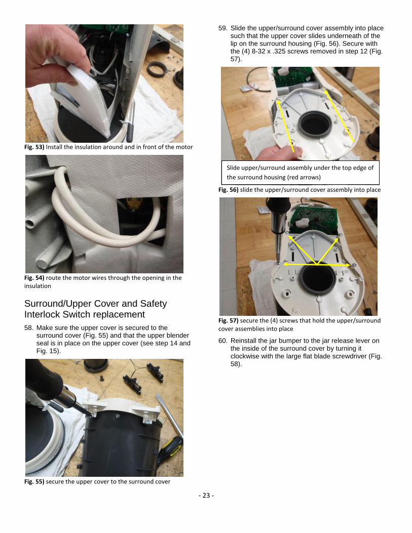
59. Slide the upper/surround cover assembly into place such that the upper cover slides underneath of the lip on the surround housing (Fig. 56). Secure with the (4) 8-32 x .325 screws removed in step 12 (Fig. 57).
Fig. 56) slide the upper/surround cover assembly into place
Fig. 57) secure the (4) screws that hold the upper/surround cover assemblies into place
60. Reinstall the jar bumper to the jar release lever on the inside of the surround cover by turning it clockwise with the large flat blade screwdriver (Fig. 58).
Slide upper/surround assembly under the top edge of
the surround housing (red arrows)

- 24 -
Fig. 58) Reinstall the jar bumper from the inside of the front plastic housing by turning out counter-clockwise
61. Mount the safety interlock switches on the upper cover and secure with the (4) 6-32 x .250 screws (Fig. 59).
Fig. 59) secure the (4) screws that hold safety interlock switches into place
62. Plug the speaker wire harness into the electronic control circuit board. Plug the safety interlock switch harness in next to the speaker wire harness (Fig. 60).
Fig. 60) plug the speaker and safety interlock switch wire harnesses into the electronic control circuit board
Upper Housing Reassembly
63. Snap the UI control into place in the front of the upper housing. This is most easily accomplished by inserting the UI straight in and pressing until it snaps in over the (plastic) retaining tabs (Fig. 61).
Fig. 61) Snap the UI into place in the upper housing
64. Place the collar back into the top of the upper housing making sure to line it up the keyed slot in the cover. Secure it to the upper housing with the (3) 8-16 x .562 screws removed in step 7 (Fig. 62).
Safety Interlock Switch plug
Speaker wire harness plug

- 25 -
Fig. 62) secure the collar to the upper housing with 3 screws
65. While holding the upper housing assembly with one hand, plug the UI wire harness into the electronic control circuit board opposite the speaker and safety interlock switch (Fig. 63).
Fig. 63) Plug the UI wire harness into the electronic control circuit board
66. Place the upper housing onto the blender assembly being careful not to pinch the UI ribbon cable between the collar and gasket. Secure the housing with the back housing screw first, and then invert the entire blender assembly and replace the remaining (2) upper housing screws through the bottom of the upper cover (Figs. 64 & 65).
Fig. 64) Secure the upper housing to the blender assembly by tightening the rear housing screw
Fig. 65) Replace the final (2) screws into the upper housing with the blender inverted
67. Upright the blender and replace the sleeve, the ingredient cap and the jar.
68. Perform ground continuity and dielectric withstand tests (HiPot) on the unit to make sure there are no open or shorted circuits within the repaired unit.
69. Plug the blender in and with approximately ½ jar of water test the operation of the unit. Make sure you have the lid installed properly on the jar for testing.
70. Wipe down the exterior of the blender after testing so that it will look its best when returning it to the customer.

- 26 -
Appendix A
Tools Required for Torrent Blender Service
Fig. 66) Hand Tools required for repair of the KitchenAid Magnetic Drive Torrent Blender.
Tool List: 1. #R2 Square Bit Screwdriver 2. #2 Phillips Screwdriver 3. Large Flat Blade Screwdriver 4. 5/32” Hex Wrench 5. Small (narrow blade) screwdriver 6. Soft work surface (soft towel or foam matting)
1 2
3
4 5
5
6

- 27 -
Appendix B
Troubleshooting Quick Reference Guide
Problem Cause Solution
Blender does not run at all
(no lights).
Unit not plugged in Plug into a grounded 3 prong outlet.
Faulty Power Receptacle
(outlet)
Check the power supply receptacle to make sure it’s
“hot.” Check receptacle breaker and/or receptacle
wiring.
Damaged power cord Replace power cord.
Faulty UI switch. Replace UI switch.
Blender runs
intermittently.
Worn or broken wires Check wire connections. Repair if necessary.
Faulty motor. Check motor. If faulty, remove and replace lower
housing assembly.
Faulty Power Cord or UI
Switch Assembly.
Check Power Cord and/or Switch Assembly. If faulty,
remove and replace.
Blender does not run at
some selections.
Faulty UI Dial/Switch
Assembly
Remove and replace the UI Dial/Switch Assembly.
Faulty electrical control
board
Remove and replace the electrical control board
Blender blades do not spin
properly.
Faulty blender jar assembly With the jar removed from the blender, carefully check
blade movement. If the blade does not turn freely,
replace the jar.
Jar not properly inserted
into the blender base
Make sure the jar is inserted properly against the stop
and engaged with the jar release handle.
Broken or loose belt If the blade has free movement and the jar is properly
inserted into the blender but the blades do not spin
while the blender is running, replace the drive belt.
UI Control Light flashing
slowly.
Blender is ready and
waiting for input from the
user.
After selecting the desired setting on the UI dial, the
light will flash slowly until “START” is pressed.
Blender powers on and UI
light is flashing quickly
Blender UI needs to be
reset
Reset the blender UI control by turning the dial to the
“OFF” position and then selecting the desired operating
setting. Once reset to desired setting, press “START”.

- 28 -
Troubleshooting Quick Reference Guide
(continued)
Blender vibrates on work
surface.
Worn, dirty or damaged
Feet.
Replace worn or damaged Base Foot/Feet. Remove any
dirt with a mild soap and water solution.
Jar not fully inserted into
blender housing.
Check the jar to make sure it is fully seated to the tab
and engages with the jar release handle.
Poor belt alignment. Remove the base and inspect the belt for proper
alignment to the pulleys.
Blender jar leaks Jar too full (ingredients
pushed out)
Reduce the amount of the ingredients in the jar
Faulty or broken jar Replace Jar assembly
Faulty jar lid Replace lid
Appendix C
Torrent Blender Screw Torques
The screw torque values used in the assembly of the Torrent (P2) Blender are as follows:
( in-lb)
(1) Lever Pivot, Shoulder Screw 30 - 35
(4) Screws for Lower Housing to Surround Housing 18 - 24
(1) Screw for Upper Housing to Surround Housing 18 - 24
(2) Screws for Upper Housing to Upper Housing Cover 18 - 24
(2) Screws for Power Board to Surround Housing 18 - 24
(1) Screw for Power Board Ground to Surround Housing 18 - 24
(1) Screw for Ground Cable to Surround Housing 18 - 24
(2) Screws for Speaker to Surround Housing 18 - 24
(4) Screws for Upper Housing Cover to Surround Housing 10 - 15
(5) Screws for Base to Lower Housing 20 - 25
(4) Screws for Interlock Switches to Upper Housing Cover 10 - 14
(1) Screw for Trim Band to Lower Housing 10 - 14
(3) Screws for Collar to Upper Housing 10 - 14
(4) Screws for Lower Housing Cover to Lower Housing 10 - 14
(2) Screws for Upper Housing Cover to Front Housing 18 - 24