kolmetz handbook of process … · 2020-04-17 · cobalt, some alloys of rare earth metals, and...
TRANSCRIPT

KLM Technology
Group
Practical Engineering Guidelines for
Processing Plant Solutions
Engineering Solutions
www.klmtechgroup.com
Page : 1 of 75
Rev: 01
Rev 01 May 2015
KLM Technology Group P. O. Box 281 Bandar Johor Bahru, 80000 Johor Bahru, Johor, West Malaysia
Kolmetz Handbook
Of Process Equipment Design
PHYSICS AND ELECTROMAGNETISM
FUNDAMENTALS
(ENGINEERING DESIGN GUIDELINES)
Co Author Riska Ristiyanti
Editor / Author Karl Kolmetz
TABLE OF CONTENT
INTRODUCTION 8
Scope 8
General Considerations 9
A. Magnet and Magnetism 9
B. Magnetic Field 12
C. Magnetic Materials and Magnetic Properties 17
DEFINITIONS 23
NOMENCLATURE 25
Greek Letter 25
THEORY 26
A. Electromagnetism 26 1. Magnetic Flux 28 2. Magnetic Flux Density 28 3. Magnetomotive Force and Magnetic Flux Intensity 31 4. Permeability 32 5. Reluctance 33 6. B-H Curve and Hysteresis Loop 35 7. Polarity 39
KLM Technology Group
Practical Engineering
Guidelines for Processing Plant Solutions
www.klmtechgroup.com
Kolmetz Handbook Of Process Equipment Design
PHYSICS AND ELECTROMAGNETISM
FUNDAMENTALS
(ENGINEERING DESIGN GUIDELINES)
Page 2 of 75
Rev: 01
May 2015
8. Electromagnetism Induction 41
B. Maxwell Equations 49
C. Magnetostatics 53 1. Current and Current Density 53 2. Ohm’s Law 54 3. Resistance 55 4. Power and Joule’s Law 56 5. Postulates of Magnetostatic 58
D. Electromagnet Radiation 60
1. Wave Properties 64 2. Doppler Effect 67 3. Planck’s Curve 68
E. Electromagnet Application 70
1. Electric Bell 71 2. Relay 72 3. Lifting Magnet 73 4. Telephone Receiver 74
REFERENCE 75
LIST OF TABLE
Table 1: Properties of Permanent Magnets 21
Table 2: Relative Permeability μ of Selected Materials at Zero Frequency
and at Room Temperature 32
Table 3: Electrical Conductivity σ and Temperature Coefficient α
(Near 20oC) for selected material at DC 55
KLM Technology Group
Practical Engineering
Guidelines for Processing Plant Solutions
www.klmtechgroup.com
Kolmetz Handbook Of Process Equipment Design
PHYSICS AND ELECTROMAGNETISM
FUNDAMENTALS
(ENGINEERING DESIGN GUIDELINES)
Page 3 of 75
Rev: 01
May 2015
LIST OF FIGURE
Figure 1: Electron spinning around nucleus produces magnetic field 9
Figure 2: Electrostatic and Magnetostatic force 10
Figure 3: Magnetic Domains 11
Figure 4: The law of Magnetic Attraction and Repulsion 12
Figure 5: Bar Magnet 12
Figure 6: Magnetic Field 13
Figure 7: Magnetic Field of a bar magnet 14
Figure 8: Magnetic Field Lines on Bar Magnet 15
Figure 9: Magornetic Field Lines for Fields Involving Two Magnet 16
Figure 10: Magnetic Field Lines in a Uniform Field 17
Figure 11: Magnetic Field Produced by Current, I 26
Figure 12: Magnetic Field Produced by Coil 27
Figure 13: Hysteresis Loop 29
Figure 14: The Magnetic Circuit 30
Figure 15: Different Physical Forms of Electromagnets 34
Figure 16: Typical B-H Curve for Two Types of Soft Iron 35
Figure 17: Hysteresis Loss 37
Figure 18: Magnetic Field Produced by Current in a Conductor 39
Figure 19: The Left-hand rule for current Carrying conductors 39
Figure 20: Left-hand rule for Coils 40
Figure 21: Left-hand rule to find North Pole of an Electromagnet 41
KLM Technology Group
Practical Engineering
Guidelines for Processing Plant Solutions
www.klmtechgroup.com
Kolmetz Handbook Of Process Equipment Design
PHYSICS AND ELECTROMAGNETISM
FUNDAMENTALS
(ENGINEERING DESIGN GUIDELINES)
Page 4 of 75
Rev: 01
May 2015
Figure 22: Induced EMF 42
Figure 23: Electromagnet Induction 43
Figure 24: Magnetic Field Rotating Around Wire 44
Figure 25: Wire in the Coil 44
Figure 26: A Short Selenoid 46
Figure 27: A Toroid Inductor 46
Figure 28: A Closely Wound Toroidal Coil 47
Figure 29: A Circuit illustrating Self-Inductance 48
Figure 30: Self-Propagating Electromagnetic Curve 50
Figure 31: The Left-Hand Rule 51
Figure 32: Conductor 55
Figure 33: Electro magnetic radiation 61
Figure 34: Visible Spectrum 62
Figure 35: Visual and radio Window of Electromagnetic Radiation 63
Figure 36: Reflection and Refraction 64
Figure 37: Raindrop 65
Figure 38: Phenomenon of Diffraction 66
Figure 39: Doppler Effect 67
Figure 40: Types of Spectrum Emitted 68
Figure 41: Plack’s Curve 70
Figure 42: Electric Bell 71
Figure 43: Relay 72
KLM Technology Group
Practical Engineering
Guidelines for Processing Plant Solutions
www.klmtechgroup.com
Kolmetz Handbook Of Process Equipment Design
PHYSICS AND ELECTROMAGNETISM
FUNDAMENTALS
(ENGINEERING DESIGN GUIDELINES)
Page 5 of 75
Rev: 01
May 2015
Figure 44: Lifting Magnet 73
Figure 45: Telephone Receiver 74
KLM Technology Group
Practical Engineering
Guidelines for Processing Plant Solutions
www.klmtechgroup.com
Kolmetz Handbook Of Process Equipment Design
PHYSICS AND ELECTROMAGNETISM
FUNDAMENTALS
(ENGINEERING DESIGN GUIDELINES)
Page 6 of 75
Rev: 01
May 2015
INTRODUCTION Scope Electromagnetism is a branch of physics which involves the study of the electromagnetic force, a type of physical interaction that occurs between electrically charged particles. The electromagnetic force (emf) is one of the four known fundamental force of nature. The other threee fundamental interactions are the strong interaction, the weak interaction and gravitation. The electromagnetic force plays a major role in determining the internal properties of most objects encountered in daily life. The emf is responsible for the functioning of a large number of devices that are important to modern civilization including radio, televsion, cellular telephones, computer and electric machinery. This paper provides an overview of the basic fundamentals of electromagnetism. The knowledge of physics and electromagnetic will help you in the design and application of electrical and electronic circuits, transmission lines, and optics.
KLM Technology Group
Practical Engineering
Guidelines for Processing Plant Solutions
www.klmtechgroup.com
Kolmetz Handbook Of Process Equipment Design
PHYSICS AND ELECTROMAGNETISM
FUNDAMENTALS
(ENGINEERING DESIGN GUIDELINES)
Page 7 of 75
Rev: 01
May 2015
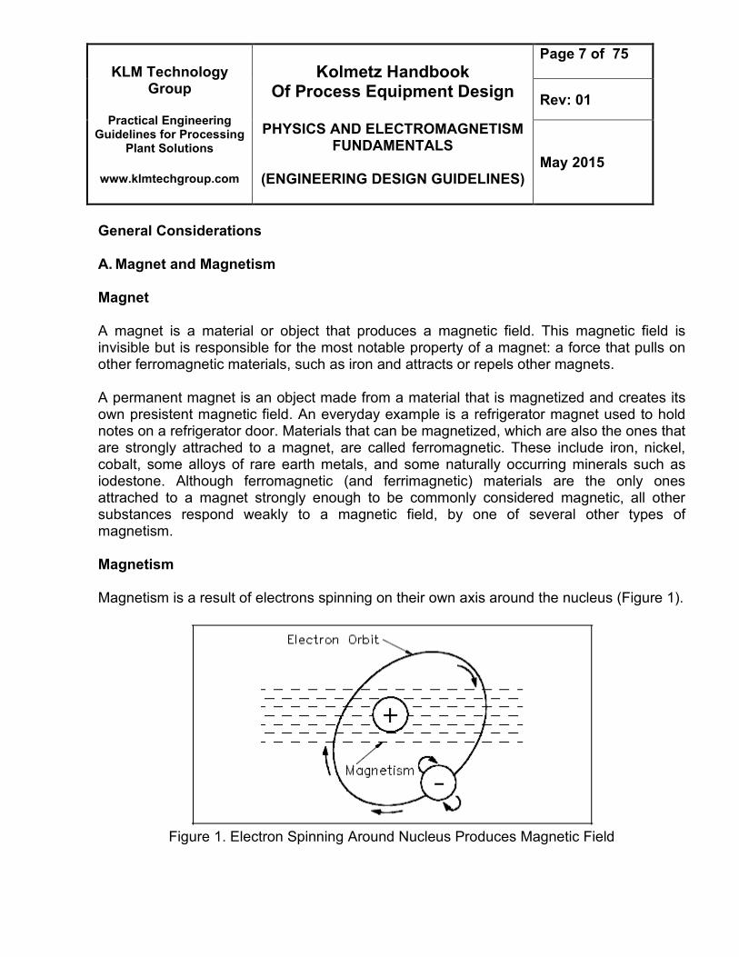
General Considerations A. Magnet and Magnetism Magnet A magnet is a material or object that produces a magnetic field. This magnetic field is invisible but is responsible for the most notable property of a magnet: a force that pulls on other ferromagnetic materials, such as iron and attracts or repels other magnets. A permanent magnet is an object made from a material that is magnetized and creates its own presistent magnetic field. An everyday example is a refrigerator magnet used to hold notes on a refrigerator door. Materials that can be magnetized, which are also the ones that are strongly attrached to a magnet, are called ferromagnetic. These include iron, nickel, cobalt, some alloys of rare earth metals, and some naturally occurring minerals such as iodestone. Although ferromagnetic (and ferrimagnetic) materials are the only ones attrached to a magnet strongly enough to be commonly considered magnetic, all other substances respond weakly to a magnetic field, by one of several other types of magnetism. Magnetism Magnetism is a result of electrons spinning on their own axis around the nucleus (Figure 1).
Figure 1. Electron Spinning Around Nucleus Produces Magnetic Field
KLM Technology Group
Practical Engineering
Guidelines for Processing Plant Solutions
www.klmtechgroup.com
Kolmetz Handbook Of Process Equipment Design
PHYSICS AND ELECTROMAGNETISM
FUNDAMENTALS
(ENGINEERING DESIGN GUIDELINES)
Page 8 of 75
Rev: 01
May 2015
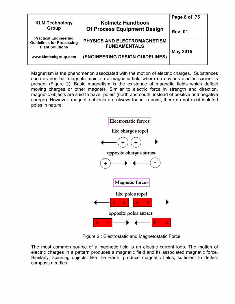
Magnetism is the phenomenon associated with the motion of electric charges. Substances such as iron bar magnets maintain a magnetic field where no obvious electric current is present (Figure 2). Basic magnetism is the existence of magnetic fields which deflect moving charges or other magnets. Similar to electric force in strength and direction, magnetic objects are said to have `poles' (north and south, instead of positive and negative charge). However, magnetic objects are always found in pairs, there do not exist isolated poles in nature.
Figure 2 : Electrostatic and Magnetostatic Force
The most common source of a magnetic field is an electric current loop. The motion of electric charges in a pattern produces a magnetic field and its associated magnetic force. Similarly, spinning objects, like the Earth, produce magnetic fields, sufficient to deflect compass needles.
KLM Technology Group
Practical Engineering
Guidelines for Processing Plant Solutions
www.klmtechgroup.com
Kolmetz Handbook Of Process Equipment Design
PHYSICS AND ELECTROMAGNETISM
FUNDAMENTALS
(ENGINEERING DESIGN GUIDELINES)
Page 9 of 75
Rev: 01
May 2015
Today we know that permanent magnets are due to dipole charges inside the magnet at the atomic level. A dipole charge occurs from the spin of the electron around the nucleus of the atom. Materials (such as metals) which have incomplete electron shells will have a net magnetic moment. If the material has a highly ordered crystalline pattern (such as iron or nickel), then the local magnetic fields of the atoms become coupled and the material displays a large scale bar magnet behavior.
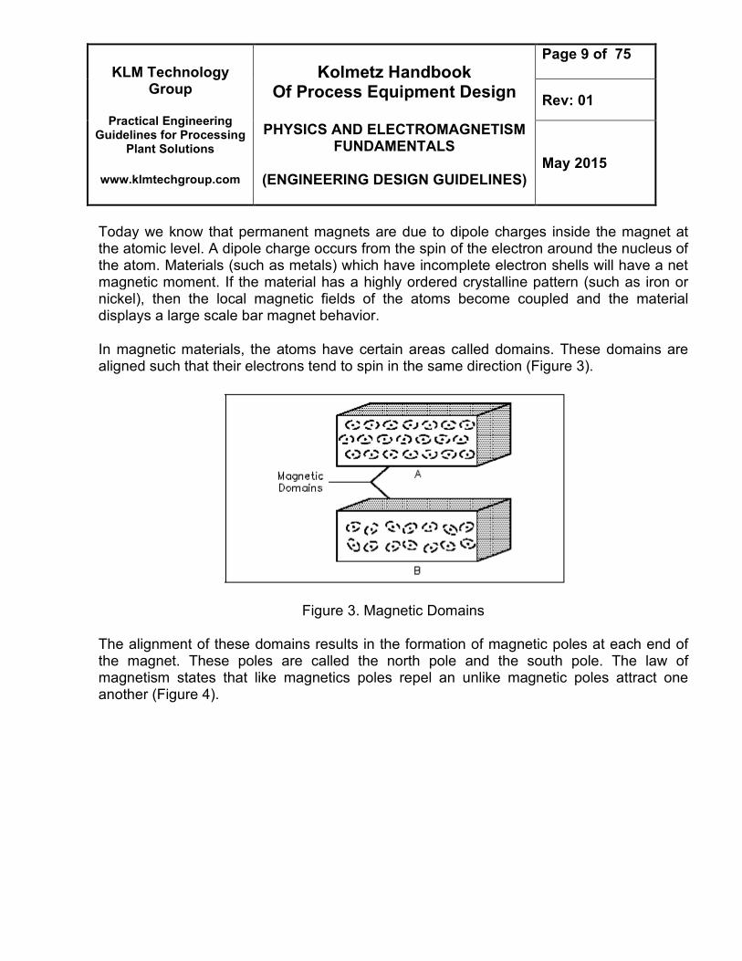
In magnetic materials, the atoms have certain areas called domains. These domains are aligned such that their electrons tend to spin in the same direction (Figure 3).
Figure 3. Magnetic Domains
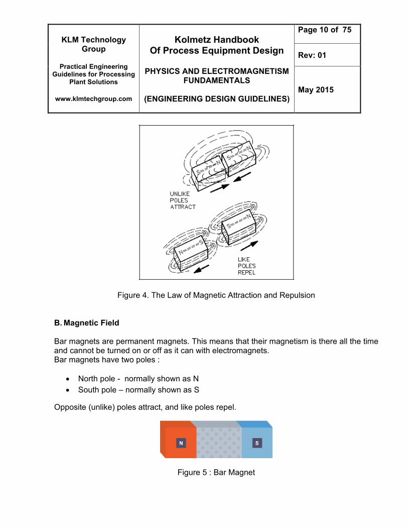
The alignment of these domains results in the formation of magnetic poles at each end of the magnet. These poles are called the north pole and the south pole. The law of magnetism states that like magnetics poles repel an unlike magnetic poles attract one another (Figure 4).
KLM Technology Group
Practical Engineering
Guidelines for Processing Plant Solutions
www.klmtechgroup.com
Kolmetz Handbook Of Process Equipment Design
PHYSICS AND ELECTROMAGNETISM
FUNDAMENTALS
(ENGINEERING DESIGN GUIDELINES)
Page 10 of 75
Rev: 01
May 2015
Figure 4. The Law of Magnetic Attraction and Repulsion
B. Magnetic Field Bar magnets are permanent magnets. This means that their magnetism is there all the time and cannot be turned on or off as it can with electromagnets. Bar magnets have two poles :
North pole - normally shown as N
South pole – normally shown as S
Opposite (unlike) poles attract, and like poles repel.
Figure 5 : Bar Magnet
KLM Technology Group
Practical Engineering
Guidelines for Processing Plant Solutions
www.klmtechgroup.com
Kolmetz Handbook Of Process Equipment Design
PHYSICS AND ELECTROMAGNETISM
FUNDAMENTALS
(ENGINEERING DESIGN GUIDELINES)
Page 11 of 75
Rev: 01
May 2015
If permanent magnets are repeatedly knocked, the strength of their magnetic field is reduced. Converting a magnet to a non-magnet is called demagnetisation. Magnets are made from magnetic metals - iron, nickel and cobalt. These are the only pure metals that can be turned into a permanentmagnet. Steel is an alloy of iron and so can also be made into a magnet. If these metals have not been turned into a permanent magnet they will still be attracted to a magnet if placed within a magnetic field. In this situation they act as a magnet but only whilst in the magnetic field. This is called induced magnetism.
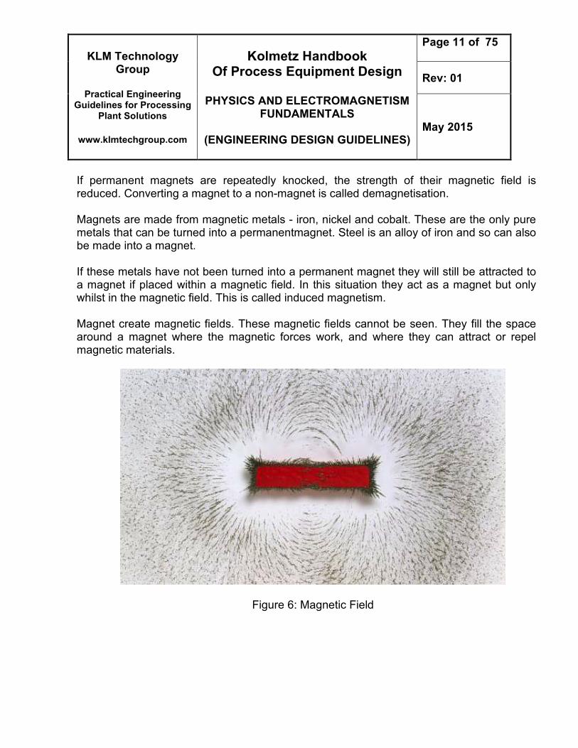
Magnet create magnetic fields. These magnetic fields cannot be seen. They fill the space around a magnet where the magnetic forces work, and where they can attract or repel magnetic materials.
Figure 6: Magnetic Field
KLM Technology Group
Practical Engineering
Guidelines for Processing Plant Solutions
www.klmtechgroup.com
Kolmetz Handbook Of Process Equipment Design
PHYSICS AND ELECTROMAGNETISM
FUNDAMENTALS
(ENGINEERING DESIGN GUIDELINES)
Page 12 of 75
Rev: 01
May 2015
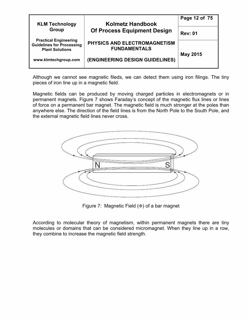
Although we cannot see magnetic fileds, we can detect them using iron filings. The tiny pieces of iron line up in a magnetic field. Magnetic fields can be produced by moving charged particles in electromagnets or in permanent magnets. Figure 7 shows Faraday’s concept of the magnetic flux lines or lines of force on a permanent bar magnet. The magnetic field is much stronger at the poles than anywhere else. The direction of the field lines is from the North Pole to the South Pole, and the external magnetic field lines never cross.
Figure 7: Magnetic Field (Φ) of a bar magnet
According to molecular theory of magnetism, within permanent magnets there are tiny molecules or domains that can be considered micromagnet. When they line up in a row, they combine to increase the magnetic field strength.
KLM Technology Group
Practical Engineering
Guidelines for Processing Plant Solutions
www.klmtechgroup.com
Kolmetz Handbook Of Process Equipment Design
PHYSICS AND ELECTROMAGNETISM
FUNDAMENTALS
(ENGINEERING DESIGN GUIDELINES)
Page 13 of 75
Rev: 01
May 2015
Drawing Magnetic Field Diagram
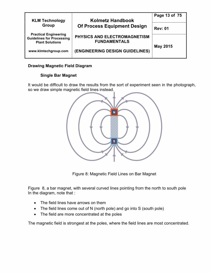
Single Bar Magnet It would be difficult to draw the results from the sort of experiment seen in the photograph, so we draw simple magnetic field lines instead.
Figure 8: Magnetic Field Lines on Bar Magnet
Figure 8, a bar magnet, with several curved lines pointing from the north to south pole In the diagram, note that :
The field lines have arrows on them
The field lines come out of N (north pole) and go into S (south pole)
The field are more concentrated at the poles
The magnetic field is strongest at the poles, where the field lines are most concentrated.
KLM Technology Group
Practical Engineering
Guidelines for Processing Plant Solutions
www.klmtechgroup.com
Kolmetz Handbook Of Process Equipment Design
PHYSICS AND ELECTROMAGNETISM
FUNDAMENTALS
(ENGINEERING DESIGN GUIDELINES)
Page 14 of 75
Rev: 01
May 2015
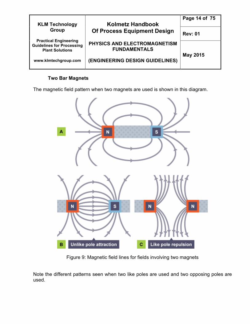
Two Bar Magnets
The magnetic field pattern when two magnets are used is shown in this diagram.
Figure 9: Magnetic field lines for fields involving two magnets
Note the different patterns seen when two like poles are used and two opposing poles are used.
KLM Technology Group
Practical Engineering
Guidelines for Processing Plant Solutions
www.klmtechgroup.com
Kolmetz Handbook Of Process Equipment Design
PHYSICS AND ELECTROMAGNETISM
FUNDAMENTALS
(ENGINEERING DESIGN GUIDELINES)
Page 15 of 75
Rev: 01
May 2015
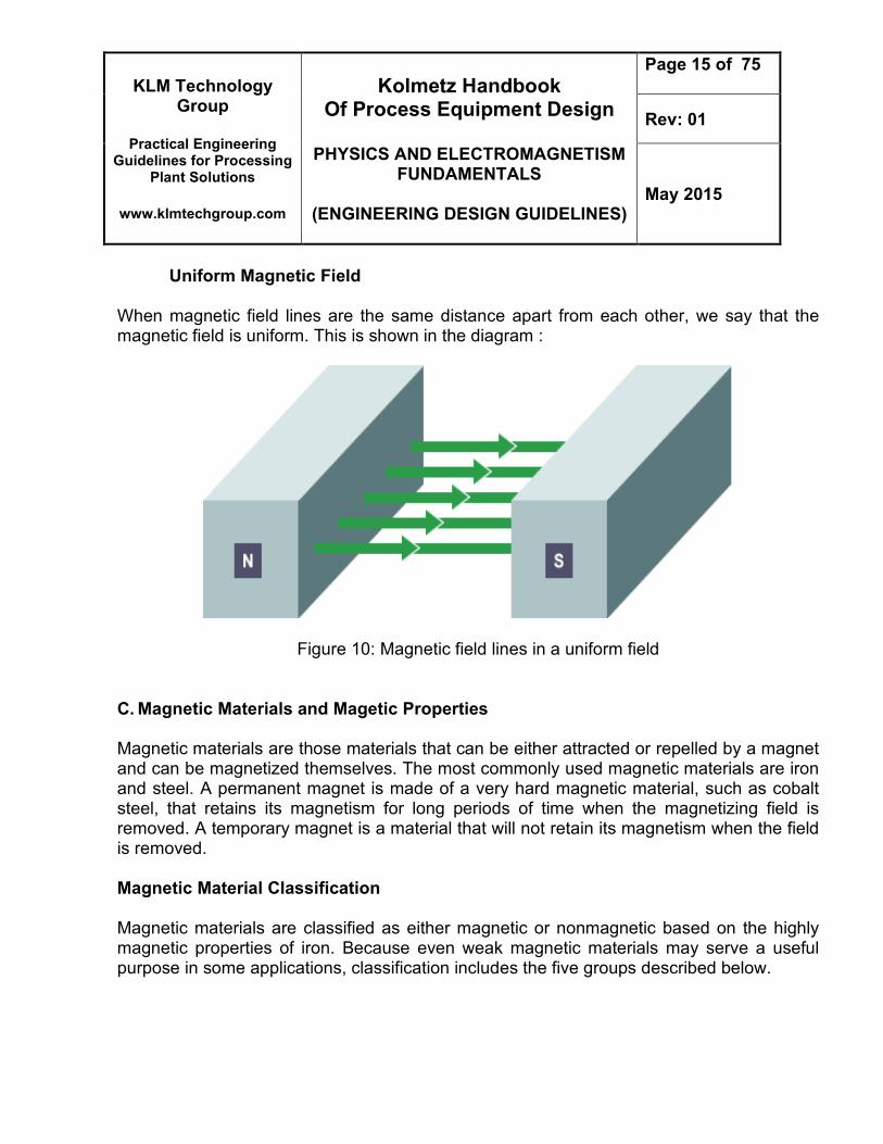
Uniform Magnetic Field
When magnetic field lines are the same distance apart from each other, we say that the magnetic field is uniform. This is shown in the diagram :
Figure 10: Magnetic field lines in a uniform field
C. Magnetic Materials and Magetic Properties
Magnetic materials are those materials that can be either attracted or repelled by a magnet and can be magnetized themselves. The most commonly used magnetic materials are iron and steel. A permanent magnet is made of a very hard magnetic material, such as cobalt steel, that retains its magnetism for long periods of time when the magnetizing field is removed. A temporary magnet is a material that will not retain its magnetism when the field is removed. Magnetic Material Classification Magnetic materials are classified as either magnetic or nonmagnetic based on the highly magnetic properties of iron. Because even weak magnetic materials may serve a useful purpose in some applications, classification includes the five groups described below.
KLM Technology Group
Practical Engineering
Guidelines for Processing Plant Solutions
www.klmtechgroup.com
Kolmetz Handbook Of Process Equipment Design
PHYSICS AND ELECTROMAGNETISM
FUNDAMENTALS
(ENGINEERING DESIGN GUIDELINES)
Page 16 of 75
Rev: 01
May 2015
Diamagnetic Materials
All materials are diamagnetic to some extent although this behaviour may be
superceded by a more dominant effect, such as ferromagnetism. Diamagnetism is a
classical effect produced by moving charges. The induced magnetization M is
opposed to the applied B, thus reducing the total B in such a material sample. This
effect is directly analogous to the polarization effects in ordinary dielectrics. These
are materials such as bismuth, antimony, copper, zinc, mercury, gold, and silver.
These materials have a relative permeability of less than one.
Paramagnetic Materials
Paramagnetism is a quantum mechanical effect largely due to the spin magnetic moment of the electron. These are materials such as alumunium, platinum, maganese, and chromium. These materials have a relative permeability of slihtly more than one.
Ferromagnetic Materials
There is a much stronger quantum mechanical interaction between neighboring spin
moments than with paramagnetic materials. Some of the feromagnetic or
nonmagnetic materials used are iron, steel, nickel, cobalt and the commercial alloys,
alnico and peralloy. Ferrites are nonmagnetic, but have the ferromagnetic properties
of iron. Ferrities are made of ceramic material and have relative permeabilities that
range from 50 to 200. They are commonly used in the coils for RF (Ratio Frequency)
transformers.
KLM Technology Group
Practical Engineering
Guidelines for Processing Plant Solutions
www.klmtechgroup.com
Kolmetz Handbook Of Process Equipment Design
PHYSICS AND ELECTROMAGNETISM
FUNDAMENTALS
(ENGINEERING DESIGN GUIDELINES)
Page 17 of 75
Rev: 01
May 2015
Magnetic Properties
Low Carbon Steels
Low carbon steel provides the path for the magnetic flux in most electrical machines :
generators, transformers and motors. Low carbon steel is used because of its high
permeability, this is, a large amount of flux can be produced with the expenditure of minimal
magnetizing “effort”, and it has low hystersis thus minimizing losses associated with the
magnetic field. High levels of flux mean more powerful machines can be produced for a
given size and weight.
Hot – rolled steel
Electrical sheet steels from which the laminations are cut are produced by a process of
rolling in the steel mill. The steels have a crystalline structure and the magnetic properties
of the sheet are derived from the magnetic properties of the individual crystals or grains.
The grains themselves are anisotropic. That is, their properties differ according to the
direction along the crystall that these are measured.
Grain – oriented steel
As early as the 1920s it had been recognized that if the individual steel crystals could be
aligned, a steel could be produced which, in one direction, would exhibit properties related
to the optimum magnetic properties of the crystals. This material is known as cold-rolled
grain-oriented steel. It is reduced in the steel mill by a hot rolling process until it is about 2
mm thick. Thereafter it is further reduced by a series of cold reductions interspersed with
annealing at around 900oC to around 0.3 mm final thickness. In order to reduce surface
oxidation and prevent the material sticking to the rolls, the steel is given a phosphate
coating in the mill. Gain-oriented steel has magnetic properties in the rolling direction which
are very much superior to those perpendicular to the rolling direction.
KLM Technology Group
Practical Engineering
Guidelines for Processing Plant Solutions
www.klmtechgroup.com
Kolmetz Handbook Of Process Equipment Design
PHYSICS AND ELECTROMAGNETISM
FUNDAMENTALS
(ENGINEERING DESIGN GUIDELINES)
Page 18 of 75
Rev: 01
May 2015
High – Permeability Steel
Cold-rolled steel as described above continued to be steadily improved until the end of
1960s when a further step-change was introduced by the Nippon Steel Corporation of
Japan. By introducing significant changes into the cold rolling process they achieved a
considerable improvement in the degree of grain orientation compared with the previous
grain-oriented material. This coating imparts a tensile stress into the steel which has the
effect of reducing hystersis loss. The reduces hystersis loss allows some reduction in the
amount of silicon which improves the workability of the material, reducing cutting burrs and
avoiding the need for these to be ground off. This coupled with the better insulation
properties of the coating means that additional; insulation is not required. The core
manufacturing process is simplified and the core itself has a better stacking factor.
Domain-refined steel
Crystals of grain-oriented steel become aligned during the grain-orientation process in large
groups. These are known as domains. There is a protion of the core loss which is related to
the size of the domains so that this can be reduced by reducing the domain size. Domain
size can be reduced after cold rolling by introducing a small amount of stress into the
material. This is generally carried out by a process of laser etching so that this type of steel
is frequently referred to as laser-etched. Improvements to the rolling process have also
enabled this material to be produced in thinner sheets, down to 0.23 mm, with resulting
further reduction in eddy-current loss.
Amorphous Steel
Amorphous steels have developed in a totally different direction to the silicon steels
described above. Amorphous steels have a non-crystalline structure. The atoms are
randomly distributed within the material. They are produced by very rapid cooling of the
molten alloy which contains about 20% of a glass forming element such as boron. The
material is generally produced by spraying a stream of molten alloy onto a rapidly rotating
copper drum. The molten material is cooled at the rate of about 106 degrees C per second
and solidifies to form a continuous thin ribbon. This requires annealing between 200 and
KLM Technology Group
Practical Engineering
Guidelines for Processing Plant Solutions
www.klmtechgroup.com
Kolmetz Handbook Of Process Equipment Design
PHYSICS AND ELECTROMAGNETISM
FUNDAMENTALS
(ENGINEERING DESIGN GUIDELINES)
Page 19 of 75
Rev: 01
May 2015
280C to develop the required magnetic properties. The earlies quantities of the material
were only 2 mm wide and about 0.025 – 0.05 mm thick.
Designation of core steels
Specification of magnetic materials including core steels is covered internationally by
standards. There is a multi-part document covering all aspect and types of magentic
materials used in the electrical industry.
Permanet Magnets (Cast) Great advances have been made in the development of materials suitable for the production of permanent magnets. The earliest materials were tungsten and chromium steel, followed by the series of cobalt steels. Alni was the first of the alumunium-nickel-iron alloys to be discovered and with the addition of cobalt, titanium and niobium, the Alnico series of magnets was developed, the properties of which varied according to composition. These are hard and brittle and can only be shaped by grinding, although a certain amount of drilling is possible on certain composition after special heat treatment. The Permanent Magnet Association (disbanded March 1975) discovered that certain alloys when heat-treated in a strong magnetic field became anistropic. That is they develop high properties high properties in the direction of the field at the expense of properties in other direction.
Permanent Magnets (Sintered) The techniques of powder metallurgy have been applied to both the isotropic and anisotropic Alnico types and it is possible to produce sintered permanet magnets which have approximatelly 10% poorer remanence and energy than cast magnets. More precise shapes are possible when using this method of production and it is economical for the production of large quantites of small magnets. Sintering techniques are also used to manufacture the oxide permanent magnets based on barium or strontium hexaferrite. These magnets which may be isotropic or anisotropic, have higher coercive force but lower remanence than the alloy magnets. They have the physical properties of ceramics, and inferior temperature stability, but their low cost makes them
KLM Technology Group
Practical Engineering
Guidelines for Processing Plant Solutions
www.klmtechgroup.com
Kolmetz Handbook Of Process Equipment Design
PHYSICS AND ELECTROMAGNETISM
FUNDAMENTALS
(ENGINEERING DESIGN GUIDELINES)
Page 20 of 75
Rev: 01
May 2015
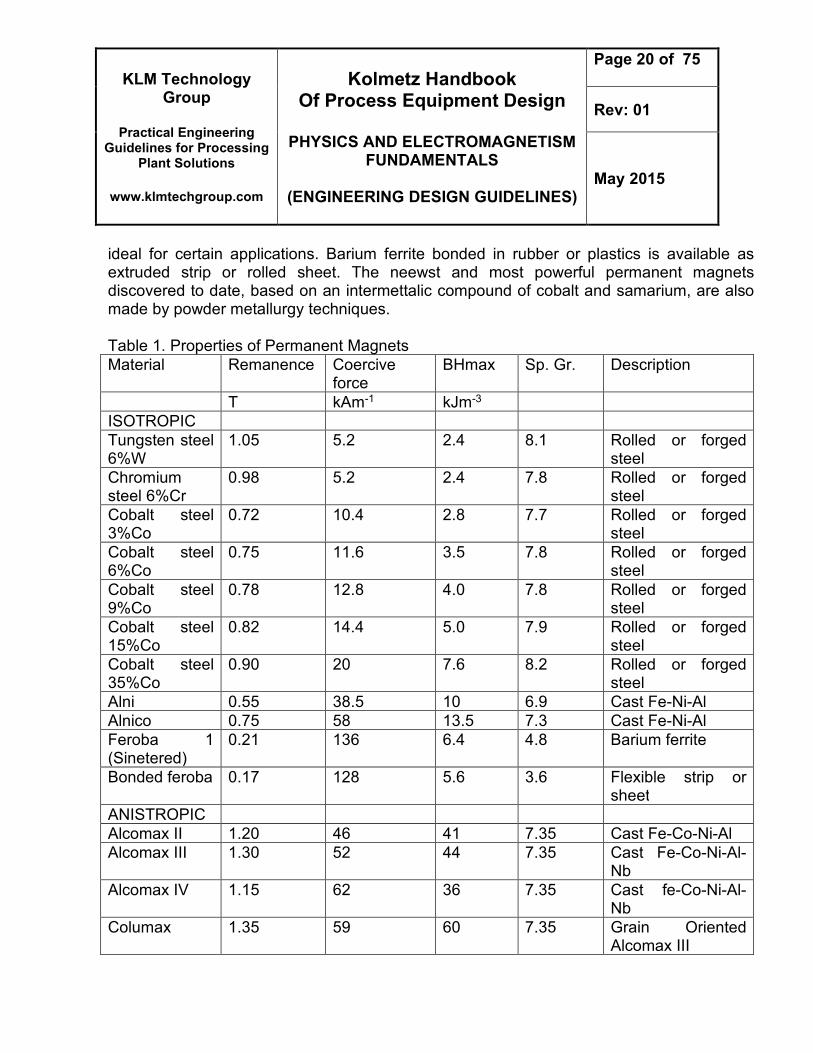
ideal for certain applications. Barium ferrite bonded in rubber or plastics is available as extruded strip or rolled sheet. The neewst and most powerful permanent magnets discovered to date, based on an intermettalic compound of cobalt and samarium, are also made by powder metallurgy techniques. Table 1. Properties of Permanent Magnets
Material Remanence Coercive force
BHmax Sp. Gr. Description
T kAm-1 kJm-3
ISOTROPIC
Tungsten steel 6%W
1.05 5.2 2.4 8.1 Rolled or forged steel
Chromium steel 6%Cr
0.98 5.2 2.4 7.8 Rolled or forged steel
Cobalt steel 3%Co
0.72 10.4 2.8 7.7 Rolled or forged steel
Cobalt steel 6%Co
0.75 11.6 3.5 7.8 Rolled or forged steel
Cobalt steel 9%Co
0.78 12.8 4.0 7.8 Rolled or forged steel
Cobalt steel 15%Co
0.82 14.4 5.0 7.9 Rolled or forged steel
Cobalt steel 35%Co
0.90 20 7.6 8.2 Rolled or forged steel
Alni 0.55 38.5 10 6.9 Cast Fe-Ni-Al
Alnico 0.75 58 13.5 7.3 Cast Fe-Ni-Al
Feroba 1 (Sinetered)
0.21 136 6.4 4.8 Barium ferrite
Bonded feroba 0.17 128 5.6 3.6 Flexible strip or sheet
ANISTROPIC
Alcomax II 1.20 46 41 7.35 Cast Fe-Co-Ni-Al
Alcomax III 1.30 52 44 7.35 Cast Fe-Co-Ni-Al-Nb
Alcomax IV 1.15 62 36 7.35 Cast fe-Co-Ni-Al-Nb
Columax 1.35 59 60 7.35 Grain Oriented Alcomax III
KLM Technology Group
Practical Engineering
Guidelines for Processing Plant Solutions
www.klmtechgroup.com
Kolmetz Handbook Of Process Equipment Design
PHYSICS AND ELECTROMAGNETISM
FUNDAMENTALS
(ENGINEERING DESIGN GUIDELINES)
Page 21 of 75
Rev: 01
May 2015
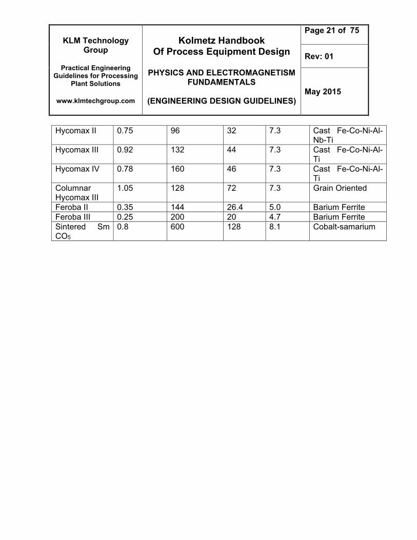
Hycomax II 0.75 96 32 7.3 Cast Fe-Co-Ni-Al-Nb-Ti
Hycomax III 0.92 132 44 7.3 Cast Fe-Co-Ni-Al-Ti
Hycomax IV 0.78 160 46 7.3 Cast Fe-Co-Ni-Al-Ti
Columnar Hycomax III
1.05 128 72 7.3 Grain Oriented
Feroba II 0.35 144 26.4 5.0 Barium Ferrite
Feroba III 0.25 200 20 4.7 Barium Ferrite
Sintered Sm CO5
0.8 600 128 8.1 Cobalt-samarium
KLM Technology Group
Practical Engineering
Guidelines for Processing Plant Solutions
www.klmtechgroup.com
Kolmetz Handbook Of Process Equipment Design
PHYSICS AND ELECTROMAGNETISM
FUNDAMENTALS
(ENGINEERING DESIGN GUIDELINES)
Page 22 of 75
Rev: 01
May 2015
DEFINITIONS
Conductors – Materials with electrons that are loosely bound to their atoms, or materials that permit free motion of a large number of electron. Cosmic rays – Hghly penetrating particle rays from outer space. Current – The density of the atoms in copper wire is such that the valence orbits of the individual atoms overlap. Electromagnetic spectrum – EM radiant energy arranged in order of frequency or wavelength and divided into regions within which the waves have some common specified charachteristics. Gamma rays – Electromagnetic radiation of very high energy (greather than 30 keV) emitted after nuclear reactions or by a radioactive atom when it nucleus is left in an excited state after emission of alpha or beta particles. Inductance – The property which opposes any change in the existing current. Inductance is present only when the current is changing. Inductor – A conductor used to introduce inductance into a circuit. Insulators or nonconductors – Material with electrons that are tightly bound to their atoms and require large amounts of energy to free them from the influence of the nucleus. Light – white light, when split into a spectrum of colors, is composed of a continuous range of merging colors : red, orange, yellow, green, cyan, blue, indigo, and violet. Magnet – a vector that characterizes the magnet’s overall magnetic properties. Magnetic Flux – the group of magnetic field lines emitted outward from the north pole of magnet. Magnetic Flux Density – The amount of magnetic flux per unit area of a section, perpendicular to the direction to the direction of flux.
KLM Technology Group
Practical Engineering
Guidelines for Processing Plant Solutions
www.klmtechgroup.com
Kolmetz Handbook Of Process Equipment Design
PHYSICS AND ELECTROMAGNETISM
FUNDAMENTALS
(ENGINEERING DESIGN GUIDELINES)
Page 23 of 75
Rev: 01
May 2015
Permanent magnet – an object made from a material that is magnetized and creates its own presistent magnetic field. Radio waves – Electromagnetic radiation suitable for radio transmission in the range of frequencies from about 10 kHz to about 300 MHz. Reflection – The abrupt change in the direction of propagation of a wave that strikes the boundary between different mediums. Refraction – The change in direction of a wave passing from one medium to another caused by its change in speed. Resistance – The ratio of the potential difference along a conductor to the current through the conductor Ultraviolet (UV) radiation – Electromagnetis radiations having wavelengths in the range from 0.4 nm to 3 nm. X Rays – Electromagnetic radiation of short wavelengths produced when cathode rays impinge on matter
KLM Technology Group
Practical Engineering
Guidelines for Processing Plant Solutions
www.klmtechgroup.com
Kolmetz Handbook Of Process Equipment Design
PHYSICS AND ELECTROMAGNETISM
FUNDAMENTALS
(ENGINEERING DESIGN GUIDELINES)
Page 24 of 75
Rev: 01
May 2015
NOMENCLATURE A : Area of the cross section, m2
B : Magnetic flux density, tesla E : Electric field f : Frequency, Hz Fm : Magnetomotive force, mmf H : Field Intensity, At/m I : Current, Ampere J : Volume Current Density L : Length between poles of coil, m M : Mutual Inductance, H N : Number of turns q : Charge, C R : Reluctance, At/Wb t : Time, seconds v : Average velocity, m/s V : Voltage, V Greek Letter α :Temperature Coefficient μ : Permeability ε : Permetivity θ : Angle : Magnetic flux, Webers σ : Electrical conductivity
KLM Technology Group
Practical Engineering
Guidelines for Processing Plant Solutions
www.klmtechgroup.com
Kolmetz Handbook Of Process Equipment Design
PHYSICS AND ELECTROMAGNETISM
FUNDAMENTALS
(ENGINEERING DESIGN GUIDELINES)
Page 25 of 75
Rev: 01
May 2015
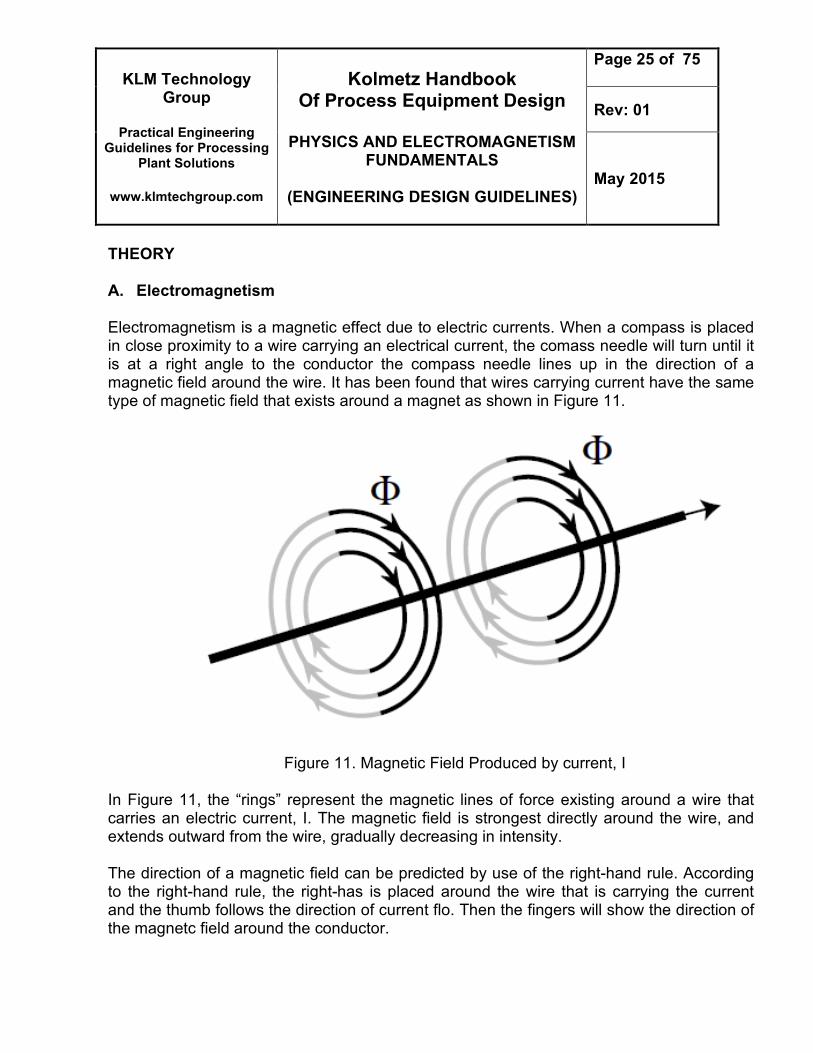
THEORY A. Electromagnetism Electromagnetism is a magnetic effect due to electric currents. When a compass is placed in close proximity to a wire carrying an electrical current, the comass needle will turn until it is at a right angle to the conductor the compass needle lines up in the direction of a magnetic field around the wire. It has been found that wires carrying current have the same type of magnetic field that exists around a magnet as shown in Figure 11.
Figure 11. Magnetic Field Produced by current, I
In Figure 11, the “rings” represent the magnetic lines of force existing around a wire that carries an electric current, I. The magnetic field is strongest directly around the wire, and extends outward from the wire, gradually decreasing in intensity. The direction of a magnetic field can be predicted by use of the right-hand rule. According to the right-hand rule, the right-has is placed around the wire that is carrying the current and the thumb follows the direction of current flo. Then the fingers will show the direction of the magnetc field around the conductor.