kraine ustainable energy lending facility … - small hydro technical... · renewable energy in...
TRANSCRIPT

Prepared for: Prepared by:
UKRAINE SUSTAINABLE ENERGY LENDING FACILITY (USELF)
Renewable Energy in Ukraine Technical Report:
Small Hydro One of five technical reports on Renewable Energy for the USELF Strategic Environmental Review

Renewable Energy in Ukraine Project
Scenarios: Small Hydro
Black & Veatch (i) September 2011
USELF RENEWABLE ENERGY IN UKRAINE PROJECT SCENARIOS: SMALL HYDRO
CONTENTS
1. INTRODUCTION .............................................................................................................. 4
2. RESOURCE AREAS AND POTENTIAL ......................................................................... 4 2.1 Existing Projects .................................................................................................... 4 2.2 Resource Areas ...................................................................................................... 4
3. TECHNOLOGY CHARACTERISTICS ............................................................................ 7 3.1 Configuration and Components ............................................................................. 7 3.2 Performance, Operations, and Maintenance ........................................................ 12 3.3 Project Summaries ............................................................................................... 13 3.4 Site Considerations .............................................................................................. 14 3.5 Construction Activities ........................................................................................ 14
Tables Table 2-1. Existing Hydropower Facilities in the Carpathian Region*. .......................................... 6 Table 3-1. General Turbine Characteristics. ................................................................................... 8 Table 3-2. Component Dimensions and Project Footprint*. ........................................................ 11 Table 3-3. Small Hydroelectric Technology Characteristics. ....................................................... 13 Figures Figure 3-1. Typical Hydroelectric Facility with Impoundment. ..................................................... 8 Figure 3-2. Turbine Size and Type Selection as Function of Head and Flow ................................. 9 Figure 3-3. Hydro Turbine-Generator Cross Section ..................................................................... 9 Figure 2-1. Map of Hydro Resources in the Ukraine. ................................................................... 17 Figure 2-2: Map of Ukraine Hydropower Potential of Small Rivers by Region ........................... 18

Renewable Energy in Ukraine Project
Scenarios: Small Hydro
Black & Veatch (ii) September 2011
Details of document preparation and issue:
Version No Prepared by Reviewed by Authorised for issue Issue date Issue status
v1 Mon Hong Neal Gruber
Mon Hong Jay Abbott May 11 2011
EBRD Bank Draft
v2 Mon Hong Mon Hong Jay Abbott
September 1, 2011
EBRD Bank Draft
v3
B&V project no. 167767 Client’s reference no. TCS ID 29098
Notice:
This report was prepared exclusively for the EBRD. The quality of information, conclusions and estimates contained herein are consistent with the level of effort involved in BV’s services and based on: i) information available at the time of preparation, ii) data supplied by outside sources and iii) the assumptions, conditions and qualifications set forth in this report. This report is intended for use by the EBRD, subject to the terms and conditions of its contract with BV. Any other use of, or reliance on, this report by any third party is at that party’s sole risk.

Renewable Energy in Ukraine Project
Scenarios: Small Hydro
Black & Veatch (iii) September 2011

Renewable Energy in Ukraine Project
Scenarios: Small Hydro
Black & Veatch 4 September 2011
USELF RENEWABLE ENERGY IN UKRAINE PROJECT SCENARIOS: SMALL HYDRO
1. INTRODUCTION
The purpose of this technical report is to provide the USELF Strategic Environmental (SER) team with a representative scenario for small hydro development in Ukraine as the team develops the SER report. The analysis examines potential locations, technologies and operating conditions for the small hydro scenario. It focuses on the technical constraints associated with the availability of the resource and the technologies that employ the resource, but does not address environmental and socioeconomic constraints that will be discussed in the SER separately. This is not intended to preclude or limit the future development of other technologies that have not been identified here for review.
The report is organized into two sections:
Resource and Potential
Technology Characteristics
Section 2 (Resource and Potential) of the report provides the SER process with country-wide background of the availability and quantity of the hydro resource, as well as potential locations or higher concentrations of small hydro in Ukraine.
Section 3 (Technology Characterstics) describes the technologies that employ the resource for electricity production and details the performance characteristics, interconnection and operations and maintenance needs of the technology, as well as the availability of the technology components in Ukraine. The section also examines typical site considerations and construction activities associated with hydro projects as inputs to the SER report.
Small hydropower facilities when discussed in this report refer to installations with less than 10 MW of capacity to meet current Ukraine Green Tariff requirements.
2. RESOURCE AREAS AND POTENTIAL
2.1 This report section identifies and discusses areas of Ukraine with existing and potential future development of small hydropower projects. Existing Projects
Overall, the majority of hydropower plants in Ukraine are large installations with reservoirs located on the mainstream sections of the Dnieper and the Dniester rivers. Some installations share the river reservoir with pumped storage facilities. Figure 2-16 depicts the general location of existing hydropower projects in Ukraine.
Ukraine is also undergoing a major Hydropower Rehabilitation Project, partially funded by the World Bank, which will rehabilitate 46 hydroelectric units and associated plant equipment at nine hydroelectric plants.
2.2 Resource Areas
Beyond these large facilities, there is little detailed information that is publicly available on the hydropower potential for Ukraine for specific river basins. Several studies have been done on facilities ranging from less than 100 kW up to 30 MW in the Carpathian region through SHYCA, a small hydro research organization funded by the European Commission, as well as other river-specific studies. Estimates have been developed for hydro potential by oblast, such as the map shown in Figure 2-27. The map displays the
Renewable Energy in Ukraine Project
Scenarios: Small Hydro
Black & Veatch 5 September 2011
Ultimate and Economic potential of all River systems in the Ukraine.1 The map, however, does not specify which river basins and streams are included in the estimates of hydro potential, nor the number and size of projects being estimated.
(a) Existing Small Hydro
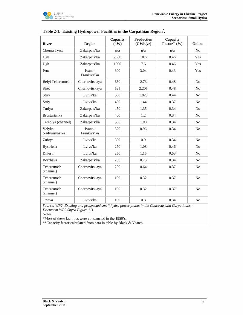
SHYCA did catalogue existing hydropower facilities in the Carpathian Region as shown in Table 2-1. As noted in the table, a significant portion of these facilities are not currently online (in operation) and are therefore candidates for rehabilitation.
(b) New Development Potential
Literature searches and discussions have identified a few key basins as having hydropower development potential for future development or rehabilitation (less then 10 MW to fit Green Tariff criteria). These areas include:
Dniester River Basin Tisa River Basin Tributaries of Dnieper and the Central Ukraine
While all of these river basins are potential candidates, only the Carpathian region has available information that provides some details on facilities and locations for consideration in development or rehabilitation.
1 Shyca WP-2 [shyca.org], 2005
Renewable Energy in Ukraine Project
Scenarios: Small Hydro
Black & Veatch 6 September 2011
Table 2-1. Existing Hydropower Facilities in the Carpathian Region*.
River Region Capacity
(kW) Production (GWh/yr)
Capacity Factor** (%) Online
Chorna Tyssa Zakarpats’ka n/a n/a n/a No
Ugh Zakarpats’ka 2650 10.6 0.46 Yes
Ugh Zakarpats’ka 1900 7.6 0.46 Yes
Prut Ivano-Frankivs’ka
800 3.04 0.43 Yes
Belyi Tcheremosh Chernovitskaya 650 2.73 0.48 No
Siret Chernovitskaya 525 2.205 0.48 No
Striy Lvivs’ka 500 1.925 0.44 No
Striy Lvivs’ka 450 1.44 0.37 No
Turiya Zakarpats’ka 450 1.35 0.34 No
Brusturianka Zakarpats’ka 400 1.2 0.34 No
Tereblya (channel) Zakarpats’ka 360 1.08 0.34 No
Velyka Nadvirnyns’ka
Ivano-Frankivs’ka
320 0.96 0.34 No
Zubrya Lvivs’ka 300 0.9 0.34 No
Bystritsia Lvivs’ka 270 1.08 0.46 No
Dniestr Lvivs’ka 250 1.15 0.53 No
Borzhava Zakarpats’ka 250 0.75 0.34 No
Tcheremosh (channel)
Chernovitskaya 200 0.64 0.37 No
Tcheremosh (channel)
Chernovitskaya 100 0.32 0.37 No
Tcheremosh (channel)
Chernovitskaya 100 0.32 0.37 No
Oriava Lvivs’ka 100 0.3 0.34 No
Source: WP2. Existing and prospected small hydro power plants in the Caucasus and Carpathians - Document WP2 Shyca Figure 1.3. Notes: *Most of these facilities were constructed in the 1950’s. **Capacity factor calculated from data in table by Black & Veatch.

Renewable Energy in Ukraine Project
Scenarios: Small Hydro
Black & Veatch 7 September 2011
3. TECHNOLOGY CHARACTERISTICS
This section discusses two types of small hydropower project--small hydro2 with an impoundment and the retrofitting or rehabilitation of existing small hydropower facilities in Ukraine. The major components required for each of the hydropower alternatives, the configuration of those components, the availability of major components in Ukraine, typical component dimensions and project costs, and interconnection requirements are included in this section.
3.1 Configuration and Components
Traditional hydroelectric power is generated by converting the potential energy of water as it moves from a higher elevation to a lower elevation and passes through a turbine to drive an electric generator. The amount of kinetic energy captured by a turbine is a function of the head3 and the water flow rate through the turbine. The building blocks for the projects identified in the SER are generally the same. They include turbines, generator sets, powerhouse, penstock, intake, control systems, and tailrace. The hydropower facilities considered in this report use the same general components but may require somewhat different configurations. For purposes of SER review, it is assumed that the hydro project scenario consists of new hydro projects with impoundments and rehabilitation of existing facilities with impoundments. In select cases, there are micro hydropower projects (<0.1 MW) that do not utilize an impoundment structure. However, these projects are rare and are more economically feasible for on-site load and not for interconnection to the grid. Since the Ukranian Green Tariff requires that projects be interconnected to the grid, these micro projects are excluded for purposes of SER review.
Dam, Diversion, or Impoundment: An impoundment is the general classification for a structure that is built across a river used to support a variety of water related purposes. A dam is a type of impoundment that can be large or small that is used to provide head or store river volume. A diversion is another type of impoundment. It typically is a dam at a lower elevation that channels or directs all or a portion of river flowtowards an intake or other water control structure. Often, the potential head and flow rate for a hydroelectric facility is improved with the construction of a dam and reservoir to increase the amount of installed hydroelectric turbine and generator capacity. This is accomplished by increasing gross head, storing inflow, providing increased discharge to the turbine-generator set, and retaining excess river flow as stored volume at a higher head for use at a later date. A typical conventional hydroelectric facility is displayed in Figure 3-1. Even though the figure is for larger installation, all components are the same as small hydro projects of interest for USELF.
2 Small hydro in this document refers to micro, mini, and small hydropower plants collectively unless noted. 3 Vertical height of the water measured from upstream of the turbine, for example a reservoir or river intake elevation, to the elevation of water downstream or below the turbine, such as the tailrace or receiving water body

Renewable Energy in Ukraine Project
Scenarios: Small Hydro
Black & Veatch 8 September 2011
Figure 3-1. Typical Hydroelectric Facility with Impoundment.
Turbines: All hydropower facilities include turbines for power generation. There are two primary types of turbine classes that are used for hydroelectric power generation, impulse turbines and reaction turbines, with design variations available for each class. Table 3-1 displays turbine designs by class, typical installed capacity range and hydropower facility type where they are installed. It is important to note where overlaps in turbine type selection occur. They are due to other factors (cost, flow variability, for example) that are important in the selection of turbines for a given installation. From Figure 3-2, note that for a 10 MW or less installation (micro, mini, and small classes), all of the turbine designs listed in Table 3-1 may be suitable, depending on site conditions. Environmental impact considerations are generally the same for any turbine type. Water Quality characteristics are generally the same comparing upstream and downstream flows. Turbines do allow for some alteration of dissolved oxygen by injection and a small hydro project can increase Dissolved Oxygen by allowing spillway discharge of river flow. Some differences that exist for these turbines include fish passage--possible for reaction turbines and not possible for impulse turbines.
Table 3-1. General Turbine Characteristics.
Turbine Design Turbine Class Capacity Range (MW) Facility Types*
Pelton Impulse 0.5 - 150 M, Mi, S, Med, L
Crossflow Impulse 0.1 – 1.0 M, Mi
Turgo Impulse (variant of Pelton) 0.75 – 5.0 M, Mi, S
Francis Reaction (fixed runners) 0.5 – 800.0 Mi, S, Med, L
Kaplan Reaction (variable pitch runners)
0.1 - 100 M, Mi, S, Med

Renewable Energy in Ukraine Project
Scenarios: Small Hydro
Black & Veatch 9 September 2011
Notes: * M=Micro (<0.1 MW)
Mi=Mini (0.1 MW – 1.5 MW) S=Small (1.5 MW – 30 MW) Med=Medium (30 MW – 100 MW) L=Large (100 MW+)
Figure 3-2 provides a more detailed summary of the potential overlap turbine type and size ranges, depending on head and flow of the site.
Figure 3-2. Turbine Size and Type Selection as Function of Head and Flow
Generator: The generator is connected and rotated by the turbine, see Figure 3-1. The turbine turns a shaft which rotates a series of magnets past copper coils and a generator to produce electricity. Electricity is produced as the rotors spin past the stationary wiring. Hydropower generators (as with other power generation) are matched and sized to the hydro turbines that rotate them. In Figure 3-2 the black lines labeled MW (megawatts) are the capacity rating of the generator that will produce that level of generation given the turbine type, flow and head selected.
Powerhouse: The powerhouse is a structure, typically reinforced concrete of one or two levels (stories), of which its primary function is to house the turbine(s), generator(s), control systems, and related equipment. Depending on where the powerhouse is sited it can be made as a watertight facility (if located in a floodplain) to prevent flood waters from damaging the generator and other electrical equipment housed inside. Often electricity is routed from the powerhouse to a step-up transformer for interconnection to a transmission line, but it is also possible for the transformer to be housed within or on top of the powerhouse.
Other facilities typically housed within the powerhouse structure may include the bypass or in-stream flow release valve and shutoff valves for use when the turbine is to be taken out of service or in cases when the flows exceed the capacity of the turbine. If these components are not able to be housed within the powerhouse then a
Figure 3-3. Hydro Turbine-Generator Cross Section

Renewable Energy in Ukraine Project
Scenarios: Small Hydro
Black & Veatch 10 September 2011
separate valve house structure will be needed. Also contiguous to the powerhouse is the draft tube and tailrace that return turbine discharge to the receiving river. Some micro and small mini hydro projects may not require a powerhouse at all and are designed to be exposed to all weather operations. Pipeline installations, where the turbines are installed directly in the pipes, are an example where a powerhouse is not always required.
Penstock: The penstock is a pipeline which directs water from the inlet at the intake structure or dam and conveys it to the powerhouse. These are often above ground for small hydropower facilities but may be tunneled as well. Penstocks may be elevated above ground if needed, and penstock components may include thrust blocks, expansion joints, supports (roller or fixed), flow meters, and valves and appurtenances. Access to the penstock is needed for inspection and maintenance activities.
Intake: An intake directs water flow into the penstock(s). As part of an impoundment structure or an intake facility, intakes require some similar design components. For example, an intake will need to be screened with a steel grate to prevent elements such as large logs from entering the penstock. Intakes will also need to have a valve installed so that flow to the penstock can be stopped for inspection and maintenance of the penstock, or in the case of emergency shutdown of the penstock.
Draft Tube and Tailrace: The draft tube conveys water from the turbine discharge to the tailrace and dissipates its energy such that impacts to the receiving body of water are minimized. It is hydraulically important and if poorly designed can increase hydraulic friction losses significantly, thereby decreasing available gross head and overall generation potential. The tailrace is the connector channel (typically an open channel that returns turbine discharge from the draft tubes to the water source at reasonable open channel flow velocities. Designs vary depending on turbine type. Poorly designed tailraces can also decrease net head and increase hydraulic losses. Cutoff gates or stop logs are usually included in tailrace design to isolate the tailrace from the draft tube for turbine and draft tube maintenance.
Control Systems: These are the systems that are used to adjust settings on the turbine and generator, and control the transfer of electricity from the hydropower project to the substation. The important environmental feature of control systems is the use of telemetered environmental data as input to decisions related to how the hydropower project is operated. The data can include, for example, river flow and hydropower discharge, quality parameters for supporting low flow, fisheries, water quality (pollutant levels), reservoir elevation, environmental releases, and or other required discharges.
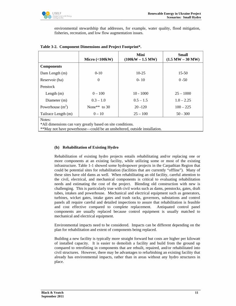
The hydro facilities considered in this report contain most or all of these components. Since the hydro projects are 10 MW or below, they fall into three typical size classes-- mini, micro, and small. Table 3-2 identifies these size ranges for the hydropower project components. In reality, the dimensions can vary widely based on a number of site specific conditions.
(a) Small Hydro With an Impoundment (Dam, Weir, or Diversion Structure)
Small hydro project with a dam, weir, or diversion structure is the expected or typical hydro facility to be installed or rehabilitated in Ukraine. The structure may or may not have a reservoir to store water. The upper limits of reservoirs and impoundments are very dependent on river, topography, and watershed characteristics. Hydropower projects with impoundments, as well as the impoundment reservoir itself, can have environmental impacts in the stream or river. Careful operations management supports good
Renewable Energy in Ukraine Project
Scenarios: Small Hydro
Black & Veatch 11 September 2011
environmental stewardship that addresses, for example, water quality, flood mitigation, fisheries, recreation, and low flow augmentation issues.
(b) Rehabilitation of Existing Hydro
Rehabilitation of existing hydro projects entails rehabilitating and/or replacing one or more components at an existing facility, while utilizing some or most of the existing infrastructure. Table 1-1 showed some hydropower projects in the Carpathian Region that could be potential sites for rehabilitation (facilities that are currently “offline”). Many of these sites have old dams as well. When rehabilitating an old facility, careful attention to the civil, electrical, and mechanical components is critical to evaluating rehabilitation needs and estimating the cost of the project. Blending old construction with new is challenging. This is particularly true with civil works such as dams, penstocks, gates, draft tubes, intakes and powerhouse. Mechanical and electrical equipment such as generators, turbines, wicket gates, intake gates and trash racks, governors, substations and control panels all require careful and detailed inspections to assure that rehabilitation is feasible and cost effective compared to complete replacement. Antiquated control panel components are usually replaced because control equipment is usually matched to mechanical and electrical equipment.
Environmental impacts need to be considered. Impacts can be different depending on the plan for rehabilitation and extent of components being replaced.
Building a new facility is typically more straight forward but costs are higher per kilowatt of installed capacity. It is easier to demolish a facility and build from the ground up compared to retrofitting in components that are rebuilt, repaired, and/or rehabilitated into civil structures. However, there may be advantages to refurbishing an existing facility that already has environmental impacts, rather than in areas without any hydro structures in place.
Table 3-2. Component Dimensions and Project Footprint*.
Micro (<100kW) Mini
(100kW – 1.5 MW) Small
(1.5 MW – 30 MW)
Components
Dam Length (m) 0-10 10-25 15-50
Reservoir (ha) 0 0- 10 0 -50
Penstock
Length (m) 0 – 100 10 - 1000 25 – 1000
Diameter (m) 0.3 – 1.0 0.5 – 1.5 1.0 – 2.25
Powerhouse (m2) None** to 30 20 -120 100 – 225
Tailrace Length (m) 0 – 10 25 – 100 50 - 300
Notes: *All dimensions can vary greatly based on site conditions. **May not have powerhouse—could be an unsheltered, outside installation.

Renewable Energy in Ukraine Project
Scenarios: Small Hydro
Black & Veatch 12 September 2011
3.2 Performance, Operations, and Maintenance
There are several factors that contribute to the performance of a hydropower project. The combination of site conditions (water flow, head, etc.), project design, and environmental/operational constraints will determine the annual capacity factor. Appropriate sizing of the facility when constructed or when rehabilitated can improve the annual capacity factor and annual generation significantly. Most of the smaller hydro projects operate primarily to sell energy and are not relied on for capacity. Therefore, revenue is maximized through increased hours of operation, resulting in higher levels of generation and higher capacity factors.4
In addition, projects with impoundments or other mechanisms to control all or part of the flow through the facility, allow for a certain degree of operational flexibility. This control can be used to maximize the value of the generation during peak demand periods, optimize the use of reservoir storage, if available, and still satisfy all environmental requirements for operations. If hydropower facilities have a reservoir, then managing reservoir storage can have several operational goals that have to be balanced for successful operations. This can include power generation, drought and flood control, water quality standards, low flow discharge requirements, in-stream and reservoir fishery and habitat requirements, recreation, irrigation and water supply.
In contrast, run-of-river (ROR) operation is a practice dictated by either regulations, by river flow and site conditions, or both. ROR means that river inflow to the hydro facility and outflow from the hydro facility, will be the same. There is no storage or modification of river discharge by ROR operations. ROR hydro projects can be designed with multiple units sized to match a wide range of river discharge. In this way, run of river projects, correctly designed for site and flow conditions, can achieve higher capacity factor values, in the range of 50-80.
Hydropower projects with dams can have some hour to hour or day to day storage changes (measured in elevation from the dam crest) depending on the size of the dam and reservoir. In this case, stream flow measurements for inflow are important to plan operations. Small reservoirs will change down stream flow if some storage volume is used to augment generation.
It is difficult to determine the actual seasonal or monthly performance of hydro projects in Ukraine, as historical operational data of existing hydro projects has not been found through literature search. When river discharge information is not available, variations in precipitation, snow accumulation and snow melt can be indicators used to estimate monthly generation for these types of facilities. Other hydrologic methods (computer modeling, stochastic hydrology, etc) are used to create stream flow records that incorporate watershed runoff characteristics. Precipitation and other meteorological data are included in these hydrologic methods. In the Carpathian region, mountainous terrain and steep slopes combine to vary runoff and stream flow significantly over a year. Snow accumulates in the mountains in winter, which delays stream flow significantly. Spring brings warmer weather, snowmelt and potentially high stream discharge levels, and possible flooding, etc. Summer is a dryer season and stream flow diminishes. Fall is generally wetter due to rain and stream flow increases again.
Often where topography and river discharge provide significant hydropower potential, multiple hydropower project have been or can be built. In these circumstances operations at each facility has to be sure that the timing of discharges from an upstream facility does not flood or excessively reduce discharge to the downstream facility or facilities.
4 Some facilities, however, are designed for specific purposes and accept lower capacity factors, such as peaking facilities. These can be as low as 25-35% if the value of power (hourly, daily, long term contract) is large enough.

Renewable Energy in Ukraine Project
Scenarios: Small Hydro
Black & Veatch 13 September 2011
Coordinated operations can maximize generation potential while meeting or exceeding environmental requirements in the river, stream and reservoir. When one company, utility, or political entity owns all facilities in a river section, the coordination and unified operations are under control of that entity and generation maximization can be more easily accomplished. When multiple owners are present, generation and river operations are more difficult because coordinating operations is much more challenging. Owners of facilities may have contract or operational goals that do not mesh well with upstream and downstream facility operations, and meeting environmental constraints and goals is also more challenging. This may be a issue as most small hydro projects in Ukraine are being developed by independent power producers, and operations need to be coordinated along river reaches and with any affected large-scale hydro projects.
3.3 Project Summaries
Hydroelectric generation is regarded as a mature technology. It is not expected to experience any significant technical advancement due to its already high reliability and efficiency. Turbine efficiencies and costs have remained somewhat stable, but construction techniques and their associated costs continue to change. The facility capacity factor (CF = the actual annual generation in kWh divided by the ideal annual generation in kWh) is highly resource dependent. CFs can range from 25 percent to more than 80 percent, although they typically range from 40 to 80 percent for run of river application to 50 to 80 percent for a facility with an impoundment structure. Historical CF for Romanian facilities in the Carpathian region has generally been in the lower portion of the CF range (see Table 3-2). Capital costs also vary widely with site conditions.
Table 3-3 displays estimated costs for both new and incremental facility capital plans. It includes cost estimates for O&M, fixed project costs, etc. that provide the necessary data for evaluating the cost of both new construction and incremental improvements to a hydropower facility.
Table 3-3. Small Hydroelectric Technology Characteristics.
Type New Project w/ Impoundment
Retrofit of Existing Facility
Performance
Typical Duty Cycle Varies Varies
Net Plant Capacity (MW) 0.1 – 10 .1 -10
Capacity Factor (percent) 50-80 50-80
Economics ($2010)
Total Project Cost ($/kW) 2600 – 4100 1500 - 4500
Fixed O&M ($/kW-yr) 5 – 26 5 -25
Variable O&M ($/MWh) 5 – 6 5 -8
(a) Interconnection and Transmission
Hydro plants use water flow to spin a turbine that drives an induction generator. Induction generators require reactive power, depending on the output power and power factor correction, which can cause self-excitation, thus increasing harmonic content. Increasing harmonic content can create stability concerns for an interconnection, especially within weaker power systems (e.g. radial distribution lines). Induction generators also have subtransient reactance inherent to the machine, which contributes to high fault current at lower voltages. Different padmount transformer configurations can also increase or

Renewable Energy in Ukraine Project
Scenarios: Small Hydro
Black & Veatch 14 September 2011
decrease the amount of fault current onto the system, so it is important to design the system to keep the zero sequence impedance to a minimum, but still have a ground reference (so no overvoltage scenarios occur). Series neutral reactors or resistors can be added to the neutral connections of the collection system to increase the zero sequence impedance, thus decreasing the fault current. For additional background on interconnection issues, see Appendix B.
Hydro projects up to 10 MW in size should typically be interconnected at distribution voltages. It is usually too costly to facilitate an interconnection at a higher voltage; however, there are no technical constraints to doing so. At distribution voltages, it is more reliable to interconnect directly to a substation, not tap a line, due to the fault contribution to the system. This type of interconnection would require a generation tie line from the project site to the substation, so siting of the tie line may pose an issue.
(b) Availability of Components in Ukraine
Hydropower is a mature, well understood industry in Ukraine. Hydropower development history in Ukraine suggests that there are industry stakeholders-- engineering firms, equipment suppliers, developers (owners), hydropower operators, and contractors with the necessary experience to support the industry. The Ukranian Hydropower Association (i.e. Association UKRHYDROENERGO) is available to support the hydropower industry and bring all stakeholders together in common cause.
3.4 Site Considerations
There are many factors which establish the feasibility of a potential site for the development of new hydropower projects and contribute to the determination of which facilities are most appropriate for a particular site. Chief amongst such considerations are the head and flow characteristics of a particular site, which dictate the power capacity and energy production capability of a facility at that site. The availability of such data also plays a role in the selection of an appropriate site. Geotechnical conditions in the vicinity of the site are also a concern. A new impoundment structure will need to have a foundation on sound material, as will the penstock and powerhouse. Areas above a proposed site will also need to have favorable geotechnical conditions so that rock falls and erosion will not endanger the facilities and that access roads may be constructed for regular inspection and maintenance activities. Environmental and socioeconomic factors will play a large role in the decision to impound a section of a river, as a new reservoir will cause the decomposition of plant matter that is inundated (releasing CO2 into the atmosphere as the plant matter decomposes over one or two decades), native habitats will change or be modified, and historical or archeological resources will need to be recovered if flooded. Proximity to existing transmission will significantly affect the economic viability of a project, as will construction duration which will be impacted by ease of access to a site as well as proximity of resources for cement production and steel.
3.5 Construction Activities
Construction activities will vary significantly for a new project with an impoundment as compared to a retrofit project. Major construction activities are identified in the following sections for each of these project types.
(a) Small Hydro with Impoundment (<10MW)
Major on-site construction activities associated with a new impoundment hydropower project will vary from project to project, but significant activities will likely include:
Topographical Survey works

Renewable Energy in Ukraine Project
Scenarios: Small Hydro
Black & Veatch 15 September 2011
Hydrological analysis of long term stream flow Geotechnical investigations and drilling Construction of access roads Installation of river diversion Mobilization of cranes and other major equipment Excavation works for temporary and permanent civil structures (dam, waterway,
powerhouse) Construction of concrete or earthen dam, including vibration and compaction of
material Installation of hydraulic steel structures Placement and installation of major equipment, valves, turbines, generator Installation of electrical work (conduits, station power, transformer, transmission
lines) (b) Retrofit / Rehab at Existing/Retired sites
Constraints to the site, limited work space, potential for damage to existing but usable facility components and structures is significant, and safety on the worksite is more challenging. Environmental control of construction materials, liquids, waste disposal, and flood protection are all more challenging in an old site being rehabilitated versus a new construction site. Construction work and site plans are important planning and operational tools. Pollution Prevention Plans need to be developed and included in site work plans. All site workers should be trained in their requirements and rules. Major on-site construction activities associated with a retrofitting an existing hydropower project will vary from project to project, but significant activities will likely include:
Installation of hydraulic steel structures Placement and installation of major equipment, valves, turbines, generator Installation of electrical work (conduits, station power, transformer, transmission
lines) In cases, where the civil works need refurbishment as well certain existing
structures are rehabilitated

Renewable Energy in Ukraine Project
Scenarios: Small Hydro
Black & Veatch 16 September 2011
FIGURES
Figure 2-4. Map of Hydro Resources in the Ukraine
Figure 2-5: Map of Ukraine Hydropower Potential of Small Rivers by Region

Renewable Energy in Ukraine Project
Scenarios: Small Hydro
Black & Veatch 17 September 2011
Figure 2-16. Map of Hydro Resources in the Ukraine.

Renewable Energy in Ukraine Project
Scenarios: Small Hydro
Black & Veatch 18 September 2011
Figure 2-27: Map of Ukraine Hydropower Potential of Small Rivers by Region