l 12/44 en official journal of the european union
TRANSCRIPT

COMMISSION DELEGATED REGULATION (EU) 201779
of 12 September 2016
establishing detailed technical requirements and test procedures for the EC type-approval of motor vehicles with respect to their 112-based eCall in-vehicles systems of 112-based eCall in-vehicle separate technical units and components and supplementing and amending Regulation (EU) 2015758 of the European Parliament and of the Council with regard to the exemptions and
applicable standards
(Text with EEA relevance)
THE EUROPEAN COMMISSION
Having regard to the Treaty on the Functioning of the European Union
Having regard to Regulation (EU) 2015758 of the European Parliament and of the Council of 29 April 2015 concerning type-approval requirements for the deployment of the eCall in-vehicle system based on the 112 service and amending Directive 200746EC (1) and in particular Article 2(2) Article 5(8) and (9) and Article 6(12) thereof
Whereas
(1) Regulation (EU) 2015758 lays down a general obligation for new types of vehicles of categories M1 and N1 to be equipped with 112-based eCall in-vehicle systems as of 31 March 2018
(2) It is necessary to set out the detailed technical requirements and test procedures for the approval of motor vehicles with respect to their 112-based eCall in-vehicle systems The test procedures also allow for testing and approval of 112-based eCall in-vehicle separate technical units (lsquoSTUsrsquo) and components intended for fitment in motor vehicles or for integration in 112-based eCall in-vehicle systems
(3) Tests should be carried out by technical services in their capacity as foreseen in Directive 200746EC of the European Parliament and of the Council (2) that establishes the general framework for the EC type-approval of motor vehicles and defines the roles and responsibilities of all the actors involved at different stages of the approval process
(4) Tests and requirements should be designed in such a way that duplicated testing is avoided In addition some flexibility is required regarding special purpose vehicles that are built in multiple stages in accordance with Directive 200746EC as they are exempted from the frontal and lateral collision requirements under UNECE Regulations 94 and 95 For that reason the approval granted at a previous stage of the process to the base vehicle with respect to the 112-based eCall in-vehicle system should remain valid unless the system or its sensors were modified after the approval
(5) There are cases where certain classes of vehicles cannot for technical reasons be fitted with an appropriate eCall triggering mechanism and should be exempted from the requirements of Regulation (EU) 2015758 Following an assessment of the costs and benefits carried out by the Commission and taking into account the relevant safety and technical aspects those classes of vehicles are identified and included in a list established in Annex IX
(6) The 112-based eCall in-vehicle system needs to remain functional after a severe accident An automatic eCall is most beneficial in a high-severity collision where the risk of occupants of the vehicle being incapacitated and not able to call for assistance without an eCall system is highest The 112-based eCall in-vehicle systems components and STUs should therefore be tested to verify their sustained functionality after being subjected to inertial loads similar to those that may occur during a severe vehicle crash
1712017 L 1244 Official Journal of the European Union EN
(1) OJ L 123 1952015 p 77 (2) Directive 200746EC of the European Parliament and of the Council of 5 September 2007 establishing a framework for the approval of
motor vehicles and their trailers and of systems components and separate technical units intended for such vehicles (Framework Directive) (OJ L 263 9102007 p 1)
(7) The post-crash functioning and automatic triggering of the 112-based eCall in-vehicle system should also be ensured at vehicle level A full-scale impact test procedure should therefore be set out to verify that the vehicle is constructed in such a way that its 112-based eCall in-vehicle system survives a frontal and side collision in its original mounting situation and configuration
(8) The core functionality of a 112-based eCall in-vehicle system is not only to notify the Public Safety Answering Point (lsquoPSAPrsquo) of an accident but also to establish a voice connection between occupants of the vehicle and a PSAP operator The audio equipment of the 112-based eCall in-vehicle system should therefore be tested after the full-scale crash tests to guarantee that it does not suffer loudness reduction or distortions that make voice communication impossible
(9) Where a 112-based eCall in-vehicle system is approved for use in conjunction with a system providing third party services (lsquoTPS systemrsquo) it should be ensured that only one of those systems is active at a time and that the 112-based eCall in-vehicle system is triggered automatically when the TPS system does not function The manufacturer of vehicles fitted with 112-based eCall in-vehicle system and TPS system should explain the fall- back procedure built-in the TPS system and describe the principles of the changeover mechanism between the TPS system and the 112-based eCall in-vehicle system
(10) To ensure the provision of accurate and reliable position information the 112-based eCall in-vehicle system should be able to use the positioning services provided by the Galileo and the EGNOS systems
(11) The 112-based eCall in-vehicle system should warn the occupants of a vehicle in the event the system is unable to execute an emergency call A procedure should therefore be set out for the verification of the self-testing of the system and of its compliance with the malfunction indication requirements
(12) Manufacturers should ensure that the 112-based eCall in-vehicle systems are not traceable and not subject to any constant tracking For that purpose a test procedure should be set out to verify that the 112-based eCall in- vehicle system is not available for communication with the PSAP before the eCall is triggered
(13) Any data processed through the 112-based eCall in-vehicle system must be adequate relevant and proportionate to the purposes for which those data are collected and processed To that end appropriate procedures should be laid down to verify that the data in the internal memory of the system are automatically and continuously removed and are not retained longer than necessary for the purpose of handling the emergency call
(14) The versions of the applicable standards on which the requirements for eCall are based should be updated
(15) Vehicle manufacturers should be given sufficient time to adapt to the technical requirements for the approval of 112-based eCall in-vehicle systems The Member States should also be given sufficient time to deploy on their territory the PSAP infrastructure required for the proper receipt and handling of emergency calls For that reason the date of application of this Regulation should be the same as the date of compulsory application of the 112-based eCall in-vehicle systems in accordance with Regulation (EU) 2015758
HAS ADOPTED THIS REGULATION
Article 1
Subject matter
This Regulation establishes detailed technical requirements and test procedures for the EC type-approval of the vehicles referred to in Article 2 of Regulation (EU) 2015758 in respect of their 112-based eCall in-vehicle systems and of 112-based eCall in-vehicle separate technical units (lsquoSTUsrsquo) and components
Article 2
Classes of vehicles exempted from the requirement to be equipped with a 112-based eCall in-vehicle system
The classes of vehicles which for technical reasons cannot be fitted with an appropriate eCall triggering mechanism and for that reason are exempted from the requirement to be equipped with a 112-based eCall in-vehicle system are listed in Annex IX
1712017 L 1245 Official Journal of the European Union EN
Article 3
Multi-stage approval of special purpose vehicles
In case of multi-stage type-approval of the special purpose vehicles defined in points 51 and 55 of part A of Annex II to Directive 200746EC the type-approval granted at a previous stage in respect of the installation of a 112-based eCall in-vehicle system in the (base) vehicle shall remain valid provided that the 112-based eCall in-vehicle system and the relevant sensors are not modified
Article 4
Definitions
For the purposes of this Regulation the following definitions shall apply
(1) lsquovehicle type with regard to the installation of a 112-based eCall in-vehicle systemrsquo means motor vehicles that do not differ in such essential respects as the characteristics of the integration within the vehicle as well as the functionality and capability of essential hardware deploying an in-vehicle emergency call
(2) lsquotype of 112-based eCall in-vehicle STUrsquo means a combination of specific hardware which does not differ in such essential respects as the characteristics functionality and capability of deploying an in-vehicle emergency call when installed in a motor vehicle
(3) lsquotype of 112-based eCall in-vehicle system componentrsquo means specific hardware which does not differ in such essential respects as the characteristics functionality and capability of facilitating the deployment of an in-vehicle emergency call when integrated in a 112-based eCall in-vehicle STU or 112-based eCall in-vehicle system
(4) lsquorepresentative arrangement of partsrsquo means all parts required by the 112-based eCall in-vehicle system to successfully populate and transmit in an in-vehicle emergency call the minimum set of data referred to in the standard EN 157222015 lsquoIntelligent transport systems mdash eSafety mdash eCall minimum set of datarsquo (lsquoMSDrsquo) including the control module the power source the mobile network communication module the Global Navigation Satellite System receiver and the external Global Navigation Satellite System antenna and their connectors and wiring
(5) lsquocontrol modulersquo means a component of the e-Call in-vehicle system designed to ensure the combined functioning of all modules components and features of the system
(6) lsquopower sourcersquo means the component that supplies power to the 112-based e-Call in-vehicle system including a back-up source if fitted which feeds the system after the test referred to in point 23 of Annex I
(7) lsquoeCall log filersquo means any record generated at the moment of an automatic or manual eCall activation which is stored within the internal memory of the 112-based eCall in-vehicle system and consists only of the MSD
(8) lsquoGlobal Navigation Satellite Systemrsquo (lsquoGNSSrsquo) means an infrastructure composed of a constellation of satellites and a network of ground stations which provides accurate timing and geolocation information to users having an appropriate receiver
(9) lsquoSatellite-Based Augmentation Systemrsquo (lsquoSBASrsquo) means a regional navigation satellite system for monitoring and correcting signals emitted by existing global satellite navigation systems giving the users better performance in terms of accuracy and integrity
(10) lsquocold start modersquo means the condition of a GNSS receiver when position velocity time almanac and ephemeris data are not stored in the receiver and therefore the navigation solution is to be calculated by means of a full sky search
(11) lsquoup-to-date locationrsquo means the last known vehicle position determined at the latest moment possible before generation of the MSD
1712017 L 1246 Official Journal of the European Union EN
Article 5
Requirements and test procedures for EC type-approval of motor vehicles with regard to the installation of 112-based eCall in-vehicle systems
1 EC type-approval of a vehicle with regard to the installation of a 112-based eCall in-vehicle system shall be subject to the vehicle and its system passing the tests laid down in Annexes I to VIII and complying with the relevant requirements laid down in those Annexes
2 Where the motor vehicle is fitted with a type of 112-based eCall in-vehicle STU that has been type-approved in accordance with Article 7 the vehicle and its system shall have to pass the tests laid down in Annexes II III and V and to comply with all relevant requirements laid down in those Annexes
3 Where the 112-based eCall in-vehicle system of the motor vehicle comprises one or more components that have been type-approved in accordance with Article 6 the motor vehicle and its system shall have to pass the tests laid down in Annexes I to VIII and to comply with all relevant requirements laid down in those Annexes The assessment of whether the system complies with those requirements may however partly be based on the results of the tests referred to in Article 6(3)
Article 6
Requirements and test procedures for EC type-approval of 112-based eCall in-vehicle system components
1 EC type-approval of a 112-based eCall in-vehicle system component shall be subject to the component passing the tests laid down in Annex I and complying with the relevant requirements in that Annex
2 For the purposes of paragraph 1 only the verification procedure for components laid down in point 28 of Annex I shall apply after the individual parts are subjected to the test referred to in point 23 of this Annex
3 Upon request of the manufacturer a component may additionally be tested by the technical service for compliance with the requirements set out in Annexes IV VI and VII that are relevant to the functionalities of the component Compliance with those requirements shall be indicated on the type-approval certificate issued in accordance with Article 3(3) of Commission Implementing Regulation (EU) 201778 (1)
Article 7
Requirements and test procedures for EC type-approval of 112-based eCall in-vehicle STUs
1 EC type-approval of a 112-based eCall in-vehicle STU shall be subject to the STU passing the tests laid down in Annexes I IV VI VII and VIII and complying with the relevant requirements laid down in those Annexes
2 Where the 112-based eCall in-vehicle STU comprises one or more components that have been type-approved in accordance with Article 6 the STU shall have to pass the tests laid down in Annexes I IV VI VII and VIII and to comply with all relevant requirements laid down in those Annexes The assessment of whether the STU complies with those requirements may however partly be based on the results of the test referred to in Article 6(3)
Article 8
Obligations of the Member States
Member States shall refuse to grant EC type-approval for new types of motor vehicles that do not comply with the requirements set out in this Regulation
1712017 L 1247 Official Journal of the European Union EN
(1) Commission Implementing Regulation (EU) 201778 of 15 July 2016 establishing administrative provisions for the EC type-approval of motor vehicles with respect to their 112-based eCall in-vehicle systems and uniform conditions for the implementation of Regulation (EU) 2015758 of the European Parliament and of the Council with regard to the privacy and data protection of users of such systems (see page 26 of this Official Journal)
Article 9
Amendments to Regulation (EU) 2015758
The second subparagraph of Article 5(8) of Regulation (EU) 2015758 is replaced by the following
lsquoThe technical requirements and tests referred to in the first subparagraph shall be based on the requirements set out in paragraphs 2 to 7 and on the available standards relating to eCall where applicable including
(a) EN 160722015 ldquoIntelligent transport systems mdash eSafety mdash Pan-European eCall operating requirementsrdquo
(b) EN 160622015 ldquoIntelligent transport systems mdash eSafety mdash eCall high level application requirements (HLAR)rdquo
(c) EN 164542015 ldquoIntelligent transport systems mdash ESafety mdash Ecall end to end conformance testingrdquo
(d) EN 157222015 ldquoIntelligent transport systems mdash eSafety mdash eCall minimum set of data (MSD)rdquo
(e) EN 161022011 ldquoIntelligent transport systems mdash eCall mdash Operating requirements for third party supportrdquo
(f) any additional European standards relating to the eCall system adopted in conformity with the procedures laid down in Regulation (EU) No 10252012 of the European Parliament and of the Council () or Regulations of the United Nations Economic Commission for Europe (UNECE Regulations) relating to eCall systems to which the Union has acceded
() Regulation (EU) No 10252012 of the European Parliament and of the Council of 25 October 2012 on European standardisation amending Council Directives 89686EEC and 9315EEC and Directives 949EC 9425EC 9516EC 9723EC 9834EC 200422EC 200723EC 200923EC and 2009105EC of the European Parliament and of the Council and repealing Council Decision 8795EEC and Decision No 16732006EC of the European Parliament and of the Council (OJ L 316 14112012 p 12)rsquo
Article 10
Entry into force and application
This Regulation shall enter into force on the twentieth day following that of its publication in the Official Journal of the European Union
It shall apply from 31 March 2018
This Regulation shall be binding in its entirety and directly applicable in all Member States
Done at Brussels 12 September 2016
For the Commission
The President Jean-Claude JUNCKER
1712017 L 1248 Official Journal of the European Union EN
TABLE OF CONTENTS
Page
ANNEX I mdash Technical requirements and procedures for testing the resistance of eCall in-vehicle systems to severe crashes (high-severity deceleration test)
51
ANNEX II mdash Full-scale impact test assessment 58
ANNEX III mdash Crash resistance of audio equipment 60
ANNEX IV mdash Co-existence of third party services (TPS) with the 112-based eCall in-vehicle systems 65
ANNEX V mdash Automatic triggering mechanism 67
ANNEX VI mdash Technical requirements for compatibility of eCall in-vehicle systems with the positioning services provided by the Galileo and the EGNOS systems
68
ANNEX VII mdash In-vehicle system self-test 80
ANNEX VIII mdash Technical requirements and test procedures related to privacy and data protection 82
ANNEX IX mdash Classes of vehicles referred to in Article 2 86
1712017 L 1249 Official Journal of the European Union EN
ANNEX I
Technical requirements and procedures for testing the resistance of eCall in-vehicle systems to severe crashes (high-severity deceleration test)
1 Requirements
11 Performance requirements
111 The high-severity deceleration test of eCall in-vehicle systems STUs and components carried out in accordance with point 2 shall be considered satisfactory if the following requirements are demonstrated post-deceleration acceleration event
112 MSD emission and encoding The eCall system or representative arrangement shall be able to successfully transmit an MSD to a PSAP test point
113 Incident time determination The eCall system or representative arrangement shall be able to determine an up-to-date timestamp for an eCall incident
114 Position determination The eCall system or representative arrangement shall be able to determine accurately the up-to-date vehicle location
115 Mobile network connectivity The eCall system or representative arrangement shall be able to connect to and transmit data via the mobile network
2 Test procedure
21 Purpose of the high-severity deceleration test procedure
The purpose of this test is to verify the sustained functionality of the 112-based eCall system after being subjected to inertial loads which may occur during a severe vehicle crash
22 The following tests shall be performed on a representative arrangement of parts (without a vehicle body)
221 A representative arrangement shall include all parts required by the eCall system to successfully populate and transmit the MSD in an eCall
222 This shall include the control module and the power source and any other parts required to perform the test eCall
223 This shall include the external antenna for mobile communication
224 The wiring harness may be represented only by the relevant connectors (connected to the tested components) and a length of wire The length of the wiring harness and its eventual fixation can be decided by the manufacturer in agreement with the technical service referred to in Article 3(31) of Directive 200746EC so that it is representative for the different installation configurations of the eCall system
23 Decelerationacceleration procedure
231 The following conditions shall apply
(a) The test shall be conducted at an ambient temperature of 20 plusmn 10 degC
(b) At the beginning of the test the power supply shall be charged sufficiently to allow performing the subsequent verification tests
232 The tested parts shall be connected to the test fixture by the intended mountings provided for the purpose of attaching them to a vehicle If the intended mountings of the power source are specifically designed to break in order to release the power source in an impact event they shall not be included in the test The technical service shall verify that such release in a real-life high-severity crash event shall not impair the functionality of the system (eg no disconnection from the power source)
1712017 L 1250 Official Journal of the European Union EN
233 If additional brackets or fixtures are used as part of the decelerationacceleration facility these shall provide a sufficiently rigid connection to the decelerationacceleration facility to not affect the outcome of the test
234 The eCall system shall be decelerated or accelerated in compliance with the pulse corridor that is specified in the Table and Figure The accelerationdeceleration shall be measured at a rigid part of the deceleration acceleration facility and filtered at CFC-60
235 The test pulse shall be within the minimum and maximum values as specified in the Table The maximum velocity change ΔV shall be 70 kmh [+ 0ndash 2 kmh] However if with the agreement of the manufacturer the test was performed at a higher acceleration or deceleration level a higher ΔV andor longer duration the test shall be considered satisfactory
236 The parts referred to in point 22 shall be tested in a worst case configuration Their position and orientation on the sled shall correspond to the installation recommendations of the manufacturer and shall be indicated in the type-approval certificate issued under Implementing Regulation (EU) 201778
237 Description of the test pulse
Figure
Minimum and maximum curve of the test pulse (pulse corridor)
Table
Accelerationdeceleration values of the minimum and maximum curve of the test pulse
Point Time (ms) AccelerationDeceleration (g)
A 10 0
B 34 65
C 38 65
D 46 0
E 0 16
F 25 77
G 47 77
H 60 0
1712017 L 1251 Official Journal of the European Union EN
24 Verification procedure
241 Verify that no cable connectors were unplugged during the event
242 The performance requirements shall be verified by performing a test call using the power source subjected to the high-severity deceleration
243 Before performing the test call ensure that
(a) the eCall system receives (real or simulated) GNSS signals to an extent representative of open sky conditions
(b) the eCall system has had sufficient time in a powered state to achieve a GNSS position fix
(c) one of the connection procedures defined in point 27 as agreed between the technical service and the manufacturer will be applied for any test call
(d) the dedicated PSAP test point is available to receive an eCall emitted by the 112-based system
(e) a false eCall to a genuine PSAP cannot be made over the live network and
(f) if applicable the TPS system is deactivated or will automatically switch to the 112-based system
244 Perform a test call (push mode) by applying a trigger according to the instructions of the manufacturer
245 Verify each of the following items
(a) Verify that an MSD was received by the PSAP test point This shall be verified by a record of the PSAP test point showing that an MSD emitted from the eCall system following the trigger was received and successfully decoded If the MSD decoding failed at redundancy version MSD rv0 but was successful at a higher redundancy version or in robust modulator mode as defined in ETSITS 126 267 this is acceptable
(b) Verify that the MSD contained an up-to-date timestamp This shall be verified by a test record showing that the timestamp contained in the MSD received by the PSAP test point does not deviate from the exact recorded time of the trigger activation by more than 60 seconds The transmission may be repeated if the eCall system failed to achieve a GNSS position fix before the test
(c) Verify that the MSD contained an accurate up-to-date location This shall be verified in accordance with the Vehicle Location Test Procedure as defined in point 25 by a test record showing that the deviation between IVS location and true location d_IVS is less than 150 metres and the confidence bit transmitted to the PSAP test point indicates position can be trusted
246 Clear down the test call using the appropriate PSAP test point command (eg hang up)
25 Positioning test procedure
251 The sustained functionality of the GNSS components shall be verified by comparing the location input and the location output of the system
252 The lsquoIVS locationrsquo (φIVS λIVS) shall be The location contained in an MSD transmitted to a PSAP test point while the GNSS antenna is in open sky conditions (real or simulated)
253 The lsquotrue locationrsquo (φtrue λtrue) shall be
(a) the actual location of the GNSS antenna (known location or determined with another means than the eCall system) when using real GNSS signals or
(b) the simulated location when using simulated GNSS signals
1712017 L 1252 Official Journal of the European Union EN
254 The deviation between IVS location and true location dIVS shall be calculated using the following equations
Δφ = φIVS ndash φtrue
Δλ = λIVS ndash λtrue
φm frac14φIVS thorn φtrue
2
dIVS frac14 R ffiffiffiffiffiffiffiffiffiffiffiffiffiffiffiffiffiffiffiffiffiffiffiffiffiffiffiffiffiffiffiffiffiffiffiffiffiffiffiffiffiffi
ethΔφTHORN2
thorn ethcosethφmTHORNΔλTHORN2
q
where
Δφ Difference in latitude (in radian)
Δλ Difference in longitude (in radian)
Note 1deg frac14π
180rad 1 mas = 48481368 10ndash 9 rad
φm Mean latitude (in unit suitable for the cosine calculation)
R Radius of the earth (mean) = 6 371 009 metres
255 The positioning test procedure may be repeated if the eCall system failed to achieve a GNSS position fix before the test
26 Antenna test procedure
261 If the connection procedure applied for the test call did not make use of over-the-air data transmission the sustained functionality of the mobile network antenna shall be verified by checking the antenna tuning status after the deceleration event according to the following procedure
262 Measure the voltage standing wave ratio of the external mobile network antenna after the deceleration event at a frequency within the antennas specified frequency band
2621 The measurement shall be performed with a power meter antenna analyser or SWR meter as close as possible to the antenna feed point
2622 If a power meter is used shall be calculated using the following equation
VSWR frac14
ffiffiffiffiPf
pthorn
ffiffiffiffiPr
p
ffiffiffiffiPf
p minus
ffiffiffiffiPr
p
where
Pf Forward measured power
Pr Reversereflected measured power
263 Verify that satisfies the specifications prescribed by the manufacturer for new antennas
27 Connection procedures
271 Simulated Mobile Network Procedure
2711 It shall be ensured that a TS12 call emitted by the 112-based system will be performed over-the-air via a non-public (ie simulated) mobile network and routed to the dedicated PSAP test point
2712 The dedicated PSAP test point during the test procedures shall be a PSAP simulator under the control of the technical service compliant with the applicable EN standards and certified in accordance with EN 16454 It shall be equipped with an audio interface to allow voice communication tests
1712017 L 1253 Official Journal of the European Union EN
2713 If applicable it shall be ensured that a TS11 call emitted by the TPS system will be performed over-the-air via a non-public (ie simulated) mobile network and routed to the TPSP test point
2714 The TPSP test point shall be a dedicated TPSP answering point simulator under the control of the technical service or a genuine TPSP answering point (permission by TPSP required)
2715 Mobile network coverage of at least ndash 99 dBm or equivalent is recommended for this procedure
272 Public Mobile Network Procedure
2721 It shall be ensured that a TS11 call to a long number will be emitted by the 112-based system (instead of a TS12 call) and will be performed over-the-air via a public mobile network and routed to the dedicated PSAP test point
2722 The dedicated PSAP test point during the test procedures shall be a PSAP simulator under the control of the technical service compliant with the applicable EN standards and certified in accordance with EN 16454 It shall be equipped with an audio interface to allow voice communication tests
2723 If applicable it shall be ensured that a TS11 call emitted by the TPS system will be performed over-the-air via a public mobile network and routed to the TPSP test point
2724 The TPSP test point shall be a dedicated TPSP answering point simulator under the control of the technical service or a genuine TPSP answering point (permission by TPSP required)
2725 Mobile network coverage of at least ndash 99 dBm or equivalent is recommended for this procedure
273 Wired Transmission Procedure
2731 It shall be ensured that a TS12 call emitted by the 112-based system will only be performed via a wired connection with a dedicated network simulator (bypassing any mobile network antenna) and routed to the dedicated PSAP test point
2732 The dedicated PSAP test point during the test procedures shall be a PSAP simulator under the control of the technical service compliant with the applicable EN standards and certified in accordance with EN 16454 It shall be equipped with an audio interface to allow voice communication tests
2733 If applicable it shall be ensured that a TS11 call emitted by the TPS system will be performed via a wired connection with a dedicated network simulator (bypassing any mobile network antenna) and routed to the dedicated TPSP test point
2734 The TPSP test point shall be a dedicated TPSP answering point simulator under the control of the technical service or a genuine TPSP answering point (permission by TPSP required)
28 Verification procedures for components
281 These procedures shall apply for the purposes of type-approval of a 112-based eCall in-vehicle system component in accordance with Article 5 of this Regulation
2811 These procedures shall apply after the individual parts are subjected to the deceleration test under point 23 of this Annex
282 Control module including its connectors and wire harness as described in point 224 of this Annex
2821 Verify that no cable connectors are unplugged during the event
2822 The performance requirements shall be verified by performing a test call
1712017 L 1254 Official Journal of the European Union EN
2823 Before performing the test call ensure that
(a) the eCall system receives (real or simulated) GNSS signals to an extent representative of open sky conditions
(b) the eCall system has had sufficient time in a powered state to achieve a GNSS position fix
(c) one of the connection procedures defined in point 27 as agreed between the technical service and the manufacturer will be applied for any test call
(d) the dedicated PSAP test point is available to receive an eCall emitted by the 112-based system
(e) a false eCall to a genuine PSAP cannot be made over the live network and
(f) if applicable the TPS system is deactivated or will automatically switch to the 112-based system
2824 Perform a test call (push mode) by applying a trigger according to the instructions of the manufacturer
2825 Verify each of the following items
(a) Verify that an MSD was received by the PSAP test point This shall be verified by a record of the PSAP test point showing that an MSD emitted from the eCall system following the trigger was received and successfully decoded If the MSD decoding failed at redundancy version MSD rv0 but was successful at a higher redundancy version or in robust modulator mode as defined in ETSITS 126 267 this is acceptable
(b) Verify that the MSD contained an up-to-date timestamp This shall be verified by a test record showing that the timestamp contained in the MSD received by the PSAP test point does not deviate from the exact recorded time of the trigger activation by more than 60 seconds The transmission may be repeated if the eCall system failed to achieve a GNSS position fix before the test
(c) Verify that the MSD contained an accurate up-to-date location This shall be verified in accordance with the Vehicle Location Test Procedure as defined in point 25 by a test record showing that the deviation between IVS location and true location dIVS is less than 150 metres and the confidence bit transmitted to the PSAP test point indicates lsquoposition can be trustedrsquo
2826 Clear down the test call using the appropriate PSAP test point command (eg hang up)
283 Mobile network antenna including its connectors and wire harness as described in point 224 of this Annex
2831 Verify that no cable connectors were unplugged during the event
2832 Measure the voltage standing wave ratio VSWR of the external mobile network antenna after the deceleration event at a frequency within the antennas specified frequency band
2833 The measurement shall be performed with a power meter antenna analyser or SWR meter as close as possible to the antenna feed point
2834 If a power meter is used VSWR shall be calculated using the following equation
VSWR frac14
ffiffiffiffiPf
pthorn
ffiffiffiffiPr
p
ffiffiffiffiPf
p minus
ffiffiffiffiPr
p
where
Pf Forward measured power
Pr Reversereflected measured power
2835 Verify that VSWR satisfies the specifications prescribed by the manufacturer for new antennas
1712017 L 1255 Official Journal of the European Union EN
284 Power supply (if not part of the control module) including its connectors and wire harness as described in point 224 of this Annex
2841 Verify that no cable connectors are unplugged during the event
2842 Measure if the voltage corresponds to the manufacturers specification
1712017 L 1256 Official Journal of the European Union EN
ANNEX II
Full-scale impact test assessment
1 Requirements
11 Performance requirements
111 The full-scale impact assessment of vehicles with eCall in-vehicle systems installed carried out in accordance with point 2 shall be considered satisfactory if the following requirements are demonstrated post-impact
112 Automatic triggering The eCall system shall automatically initiate an eCall after an impact in accordance with UN Regulation No 94 (Annex 3) as well as UN Regulation No 95 (Annex 4) as applicable
113 Call status indication The eCall system shall inform the occupants about the current status of the eCall (status indicator) using a visual andor audible signal
114 MSD emission and encoding The eCall system shall be able to successfully transmit an MSD to a PSAP test point via the mobile network
115 Vehicle-specific data determination The eCall system shall be able to populate accurately the mandatory vehicle- specific data fields of the MSD
116 Position determination The eCall system shall be able to determine accurately the up-to-date vehicle location
2 Test procedure
21 Purpose of the full-scale impact test procedure
The purpose of this test is to verify the automatic triggering function and the sustained functionality of the 112-based eCall in-vehicle system in vehicles that are subjected to a frontal impact or a side impact
22 The following tests shall be performed on a vehicle with an eCall in-vehicle system installed
23 Impact test procedure
231 Impact tests shall be carried out in accordance with the tests defined in UN Regulation No 94 Annex 3 for frontal impact as well as UN Regulation No 95 Annex 4 for side impact as applicable
232 The test conditions defined in UN Regulation No 94 or UN Regulation No 95 shall apply
233 Before performing the impact tests ensure that
(a) the in-vehicle power source if installed for the test is charged according to the specifications of the manufacturer at the beginning of the test to allow performing the subsequent verification tests
(b) the automatic eCall is enabled and armed and that the vehicle ignition or master control switch is activated
(c) one of the connection procedures defined in point 27 as agreed between the technical service and the manufacturer will be applied for any test call
(d) the dedicated PSAP test point is available to receive an eCall emitted by the 112-based system
(e) a false eCall to a genuine PSAP cannot be made over the live network and
(f) if applicable the TPS system is deactivated or will automatically switch to the 112-based system
24 Verification procedure
241 The performance requirements shall be verified by performing a test call from the vehicle after the impact using the 112-based eCall in-vehicle system An automatically triggered eCall following the impact test
242 Perform a test call (push mode) by applying an automatic trigger
1712017 L 1257 Official Journal of the European Union EN
243 Verify each of the following items in at least one of the test calls
(a) Verify that an eCall was triggered automatically by the full-scale impact event This shall be verified by a record of the PSAP test point showing that it received an eCall initiation signal following the impact event and that the MSD control indicator was set to lsquoautomatically initiated eCallrsquo
(b) Verify that the eCall status indicator indicated an eCall sequence following the automatic or manual trigger This shall be verified by a record showing that an indication sequence was performed on all sensory channels specified in the manufacturers documentation (visual andor audible)
(c) Verify that an MSD was received by the PSAP test point This shall be verified by a record of the PSAP test point showing that an MSD emitted from the vehicle following the automatic or manual trigger was received and successfully decoded If the MSD decoding failed at redundancy version MSD rv0 but was successful at a higher redundancy version or in robust modulator mode as defined in ETSITS 126 267 this is acceptable
(d) Verify that the MSD contained accurate vehicle-specific data This shall be verified by a record of the PSAP test point showing that the information transmitted in the fields regarding vehicle type vehicle identification number (VIN) and vehicle propulsion storage type does not deviate from the information specified in the type-approval application
(e) Verify that the MSD contained an accurate up-to-date location This shall be verified in accordance with the Vehicle Location Test Procedure as defined in point 25 of Annex I to this Regulation by a test record showing that the deviation between IVS location and true location d_IVS is less than 150 metres and the confidence bit transmitted to the PSAP test point indicates lsquoposition can be trustedrsquo If no GNSS signals are available at the impact test location the vehicle can be moved to an appropriate location before performing the test call
244 Clear down the test call using the appropriate PSAP test point command (eg hang up)
245 If the automatic test call could not be performed successfully due to vehicle-external factors it shall be permissible to verify the automatic trigger following the impact via the internal record transaction function of the in-vehicle system This register shall be capable to store received trigger signals in non-volatile memory The test engineer shall have access to the data stored in the in-vehicle system and shall verify that no record of automatic trigger signal is stored before the impact event and that a record of an automatic trigger signal is stored after the impact event
246 If the test call was performed with the vehicle connected to an off-vehicle power supply (in cases where the impact test was carried out with the standard vehicle power supply not installed) verify that the on-board electrical system feeding the eCall in-vehicle system remained intact This shall be verified by a record of a test engineer confirming a successful check of the integrity of the on-board electrical system including the dummy in-vehicle power source (visual inspection for mechanical damage to either the power sources mounting bracket or its structure) and the connections via its terminals
25 Positioning test procedure
The positioning test procedure defined in point 25 of Annex I to this Regulation shall apply
26 Antenna test procedure
261 If the connection procedure applied for the test call did not make use of over-the-air data transmission (point 273 of Annex I to this Regulation) the sustained functionality of the mobile network antenna shall be verified by checking the antenna tuning status after the full-scale impact test according to the procedure defined in point 26 of Annex I to this Regulation In addition it shall be verified that no wire breakage or short-circuit of the antenna feed line occurred by checking the electrical resistance between the end points of the wire and between the wire and vehicle ground
27 Connection procedures
The connection procedures defined in point 27 of Annex I to this Regulation shall apply
1712017 L 1258 Official Journal of the European Union EN
ANNEX III
Crash resistance of audio equipment
1 Requirements
11 Performance requirements
111 The assessment of the crash resistance of the eCall audio equipment of vehicles with eCall in-vehicle systems installed carried out in accordance with point 2 shall be considered satisfactory if the following requirements are demonstrated post-impact as regards the frontal impact test as well as the side impact test as applicable
112 Reconnection of audio equipment The eCall system shall reconnect the loudspeaker(s) and microphone(s) after being disconnected during an eCall for MSD transmission
113 Voice communication The eCall system shall allow hands-free voice communication (send and receive direction) of sufficient intelligibility between vehicle occupants and an operator
2 Test procedure
21 Purpose of the audio equipment crash resistance test procedure
The purpose of this test is to verify that loudspeaker(s) and microphone(s) are successfully reconnected after being disconnected for MSD transmission and that the audio equipment remained functional after the vehicle has been subjected to the frontal impact or the side impact test
22 The following verification test shall be performed on a vehicle with the eCall in-vehicle system installed that has been subjected to a full-scale impact according to Regulation No 94 Annex 3 for frontal impact or UN Regulation No 95 Annex 4 for side impact as set out in point 111 above
23 Overview of test procedure
231 The sustained functionality of the audio equipment shall be verified by performing a test call after the impact test and using the voice communication channel between the vehicle and the PSAP test point
232 Two test engineers positioned in the vehicle (near-end tester) and at the PSAP test point (far-end tester) respectively successively transmit (read and listen) pre-defined phonetically balanced sentences in single talk mode
233 The testers are required to assess whether they were able to understand the meaning of the transmission in the send and receive directions
24 Arrangement of testers
241 The test shall be performed in a quiet environment with a background noise level of not more than 50 dB(A) and that is free from any noise sources that might otherwise disrupt the tests
242 The near-end tester shall be positioned so that his head is close to a normal seating position on the drivers seat of the impacted vehicle The tester shall use the in-vehicle audio equipment in the original arrangement
243 The far-end tester shall be positioned away from the vehicle with sufficient separation so that speech in normal loudness from one tester cannot be understood without any aids by the other tester
25 Test setup
251 Before performing the test call ensure that
(a) one of the connection procedures defined in point 27 of Annex I to this Regulation as agreed between technical service and manufacturer will be applied for any test call
(b) the dedicated PSAP test point is available to receive an eCall emitted by the 112-based system
1712017 L 1259 Official Journal of the European Union EN
(c) a false eCall to a genuine PSAP cannot be made over the live network
(d) if applicable the TPS system is deactivated or will automatically switch to the 112-based system and
(e) the vehicle ignition or master control switch is activated
252 Where it is possible to adapt the volume setting the maximum volume control setting in send and receive direction at the near-end and at the far-end shall be chosen The volume control settings at the far-end may be decreased during the test if required for better intelligibility
253 If possible no mobile networks that have an influence on the hands-free performance (eg echo AGC noise reduction etc) should be chosen for the connection For simulated networks if possible DTX shall be switched off the full rate codec shall be used (for GSM standard) and the highest bit rate of 122 kbits shall be used (for AMR codecs)
26 Test call
261 Perform a test call (push mode) by applying a manual trigger via the in-vehicle HMI and wait until the loudspeaker(s) and microphone(s) are reconnected for voice communication after completed MSD transmission
262 Exchange of test messages
2621 Receive direction
26211 The far-end tester shall select and read one sentence pair of the list provided in the Appendix The tester shall read the sentences in a normal volume as used in phone calls
26212 The near-end tester shall assess whether the voice transmission in the receive direction was intelligible The test in receive direction is passed if the near-end tester resting in his original seating position was able with any feasible effort to understand the full meaning of the transmission
26213 If required for the assessment the near-end tester can request from the far-end tester to transmit additional sentence pairs
2622 Send direction
26221 The near-end tester shall select and resting in his original seating position read one sentence pair of the list provided in the Appendix The tester shall read the sentences in a normal volume as used in phone calls
26222 The far-end tester shall assess whether the voice transmission in the send direction was intelligible The test in send direction is passed if the far-end tester was able with any feasible effort to understand the full meaning of the transmission
26223 If required for the assessment the far-end tester can request from the near-end tester to transmit additional sentence pairs
263 Clear down the test call using the appropriate PSAP test point command (eg hang up)
264 If the requirements cannot be fulfilled due to impairments introduced by the PSAP test point or the transmission medium the test call may be repeated if required in an adapted test setup
27 Connection procedures
271 The connection procedures defined in point 27 of Annex I to this Regulation shall apply
1712017 L 1260 Official Journal of the European Union EN
Appendix
Test sentences
1 The following test sentence pairs as defined in ITU-T P501 Annex B shall be used for the exchange of test messages in the send and receive directions
2 Test sentence pairs in the language most commonly spoken by the testers shall be selected from the list below If the testers are not familiar with any of the languages alternative sentences in a familiar language preferably phonetically balanced shall be used
3 Test sentence pairs
31 Dutch
(a) Dit product kent nauwelijks concurrentie
Hij kende zijn grens niet
(b) Ik zal iets over mijn carriegravere vertellen
Zijn auto was alweer kapot
(c) Zij kunnen de besluiten nehmen
De meeste mensen hadden het wel door
(d) Ik zou liever gaan lopen
Willem gaat telkens naar buiten
32 English
(a) These days a chicken leg is a rare dish
The hogs were fed with chopped corn and garbage
(b) Rice is often served in round bowls
A large size in stockings is hard to sell
(c) The juice of lemons makes fine punch
Four hours of steady work faced us
(d) The birch canoe slid on smooth planks
Glue the sheet to the dark blue background
33 Finnish
(a) Ole aumlaumlneti tai sano sellaista joka on parempaa kuin vaikeneminen
Suuret sydaumlmet ovat kuin valtameret ne eivaumlt koskaan jaumlaumldy
(b) Jos olet vasara lyouml kovaa Jos olet naula pidauml paumlaumlsi pystyssauml
Onni tulee elaumlen ei ostaen
(c) Rakkaus ei omista mitaumlaumln eikauml kukaan voi sitauml omistaa
Naisen mieli on puhtaampi haumln vaihtaa sitauml useammin
(d) Sydaumlmellauml on syynsauml joita jaumlrki ei tunne
On opittava kaumlrsimaumlaumln voidakseen elaumlauml
1712017 L 1261 Official Journal of the European Union EN
34 French
(a) On entend les gazouillis dun oiseau dans le jardin
La barque du pecirccheur a eacuteteacute emporteacutee par une tempecircte
(b) Le client sattend agrave ce que vous fassiez une reacuteduction
Chaque fois que je me legraveve ma plaie me tire
(c) Vous avez du plaisir agrave jouer avec ceux qui ont un bon caractegravere
Le chevrier a corneacute pour rassembler ses moutons
(d) Ma megravere et moi faisons de courtes promenades
La poupeacutee fait la joie de cette tregraves jeune fille
35 German
(a) Zarter Blumenduft erfuumlllt den Saal
Wisch den Tisch doch spaumlter ab
(b) Sekunden entscheiden uumlber Leben
Flieder lockt nicht nur die Bienen
(c) Gegen Dummheit ist kein Kraut gewachsen
Alles wurde wieder abgesagt
(d) Uumlberquere die Strasse vorsichtig
Die drei Maumlnner sind begeistert
36 Italian
(a) Non bisogna credere che sia vero tutto quello che dice la gente Tu non conosci ancora gli uomini non conosci il mondo
Dopo tanto tempo non ricordo piugrave dove ho messo quella bella foto ma se aspetti un po la cerco e te la prendo
(b) Questo tormento dureragrave ancora qualche ora Forse un giorno poi tutto finiragrave e tu potrai tornare a casa nella tua terra
Lucio era certo che sarebbe diventato una persona importante un uomo politico o magari un ministro Aveva a cuore il bene della societagrave
(c) Non bisogna credere che sia vero tutto quello che dice la gente tu non conosci ancora gli uomini non conosci il mondo
Dopo tanto tempo non ricordo piugrave dove ho messo quella bella foto ma se aspetti un po la cerco e te la prendo
(d) Questo tormento dureragrave ancora qualche ora Forse un giorno poi tutto finiragrave e tu potrai tornare a casa nella tua terra
Lucio era certo che sarebbe diventato una persona importante un uomo politico o magari un ministro aveva a cuore il bene della societagrave
37 Polish
(a) Pielęgniarki były cierpliwe
Przebiegał szybko przez ulicę
(b) Ona była jego sekretarką od lat
Dzieci często płaczą kiedy są głodne
1712017 L 1262 Official Journal of the European Union EN
(c) On był czarującą osobą
Lato wreszcie nadeszło
(d) Większość droacuteg było niezmiernie zatłoczonych
Mamy bardzo entuzjastyczny zespoacuteł
38 Spanish
(a) No arroje basura a la calle
Ellos quieren dos manzanas rojas
(b) No cocinaban tan bien
Mi afeitadora afeita al ras
(c) Ve y sieacutentate en la cama
El libro trata sobre trampas
(d) El trapeador se puso amarillo
El fuego consumioacute el papel
1712017 L 1263 Official Journal of the European Union EN
ANNEX IV
Co-existence of third party services (TPS) with the 112-based eCall in-vehicle systems
1 Requirements
11 The following requirements apply to 112-based eCall in-vehicle systems STUs and (optionally for) components that shall be used in conjunction with a TPS eCall in-vehicle system
12 Performance requirements
121 The 112-based system shall be deactivated as long as the TPS system is active and does function
122 The 112-based system shall be automatically triggered in the event that the TPS system is triggered but does not function
13 Documentation requirements
131 The manufacturer shall provide the technical service with an explanation of the design provisions built into the TPS system to ensure automatic triggering of the 112-based system (lsquofall-back procedurersquo) in the event that the TPS system does not function This documentation shall describe the principles of the changeover mechanism
132 The documentation shall be supported by an analysis which shows in overall terms any hardware or software failure conditions that would result in an inability of the TPS system to perform a successful call and how the TPS system will behave on the occurrence of these
This may be based on a Failure Mode and Effect Analysis (FMEA) a Fault Tree Analysis (FTA) or any appropriate similar process as agreed between the technical service and the manufacturer
The chosen analytical approach(es) shall be established and maintained by the manufacturer and shall be made open for inspection by the technical service at the time of the type-approval
2 Test procedure
21 Purpose of the TPS co-existence test procedure
The purpose of this test procedure is to verify for eCall in-vehicle systems that shall be used in conjunction with a TPS eCall in-vehicle system that there is only one system active at a time and that the 112-based system is triggered automatically in the event that the TPS system does not function
22 The following tests shall be performed either on a vehicle with an eCall in-vehicle system installed or on a repshyresentative arrangement of parts
23 The deactivation of the 112-based system while the TPS system is active shall be verified by performing a manually triggered test call
231 Before performing the test call ensure
(a) that one of the connection procedures defined in point 27 of Annex I to this Regulation as agreed between the technical service and the manufacturer will be applied for any test call
(b) that the dedicated PSAP test point is available to receive an eCall emitted by the 112-based system
(c) that the TPSP test point is available to receive a call emitted by the TPS system
(d) that a false eCall to a genuine PSAP cannot be made over the live network and
(e) that the vehicle ignition or master control switch is activated
232 Perform a test call by applying a manual trigger of the TPS system (push mode)
1712017 L 1264 Official Journal of the European Union EN
233 Verify
(a) that a call was established with the TPSP test point by a record of the TPSP test point showing that it did receive a call initiation signal or by a successful voice connection to the TPSP test point and
(b) that no eCall was attempted or established with the PSAP test point by a record of the PSAP test point showing that it did not receive an eCall initiation signal
234 Clear down the test call using the appropriate PSAP test point command (eg hang up)
235 If the call attempt of the TPS system fails during the test the test procedure may be repeated
24 The fall-back procedure shall be verified by performing a manually triggered test call to a dedicated PSAP test point in a condition where the TPS system does not function
241 Modify the TPS system to simulate a failure selected at the discretion of the type-approval authority that shall result in a fall-back procedure based on the documentation provided by the manufacturer
242 Before performing the test call ensure
(a) that one of the connection procedures defined in point 27 of Annex I to this Regulation as agreed between the technical service and the manufacturer will be applied for any test call
(b) that the dedicated PSAP test point is available to receive an eCall emitted by the 112-based system
(c) that a false eCall to a genuine PSAP cannot be made over the live network and
(d) that the vehicle ignition or master control switch is activated
243 Perform a test call by applying a manual trigger of the TPS system (push mode)
244 Verify that an eCall was established by the 112-based system by a record of the PSAP test point showing that it did receive an eCall initiation signal
245 Clear down the test call using the appropriate PSAP test point command (eg hang up)
25 Connection procedures
The connection procedures defined in point 27 of Annex I to this Regulation shall apply
1712017 L 1265 Official Journal of the European Union EN
ANNEX V
Automatic triggering mechanism
1 Requirements
11 The following requirements apply to vehicles with eCall in-vehicle systems installed
12 Documentation requirements
121 The manufacturer shall provide a statement which affirms that the strategy chosen to trigger an automatic eCall ensures triggering also in accident configurations dissimilar from andor of a lower severity than the collisions simulated in the applicable full-scale crash tests in UN Regulation No 94 and UN Regulation No 95
122 The manufacturer shall choose the collision typology and severity and will demonstrate that it is significantly different than the full-scale crash tests
123 The manufacturer shall provide the type-approval authority with an explanation and technical documentation which shows in overall terms how this is achieved
1231 Documentation that shows to the satisfaction of the type-approval authority that the activation of supplemental restraint systems and the severity level chosen at the discretion of the manufacturer also induces an automatic eCall shall be considered satisfactory
1232 Documentation that shows to the satisfaction of the type-approval authority the strategy to prevent unjustified eCalls from being made in case of impacts of a severity level that is not considered a severe accident Moreover failure mode analysis shall be provided which shows that any hardware or software faults shall not result in automatic triggering of an eCall
1233 Airbag control unit specification drawings specification data notes sensitivity drawings relevant circuit diagrams or similar documents considered equivalent by the type-approval authority would be suitable means to demonstrate this connection
1234 The extended documentation package shall remain strictly confidential It may be kept by the approval authority or at the discretion of the approval authority may be retained by the manufacturer In case the manufacturer retains the documentation package that package shall be identified and dated by the approval authority once reviewed and approved It shall be made available for inspection by the approval authority at the time of approval or at any time during the validity of the approval
1712017 L 1266 Official Journal of the European Union EN
ANNEX VI
Technical requirements for compatibility of eCall in-vehicle systems with the positioning services provided by the Galileo and the EGNOS systems
1 Requirements
11 Compatibility requirements
111 The lsquoGalileo system compatibilityrsquo shall be the reception and processing of the signals from the Open Service of Galileo using it in the computation of the final position
112 The lsquoEGNOS system compatibilityrsquo shall be the reception of the corrections from the Open Service of EGNOS and its application to the GNSS signals in particular GPS
113 The compatibility of the eCall in-vehicle systems with the positioning services provided by the Galileo and the EGNOS systems shall be compliant with respect to positioning capabilities in section 12 and demonstrated by performing the test methods in section 2
114 The testing procedures in section 22 can be performed either on the eCall unit including post processing ability or directly on the GNSS receiver being a part of the eCall
12 Performance requirements
121 The GNSS receiver shall be able to output the navigation solution in a NMEA-0183 protocol format (RMC GGA VTG GSA and GSV message) The eCall setup for NMEA-0183 messages output shall be described in the operation manual
122 The GNSS receiver being a part of the eCall shall be capable of receiving and processing individual GNSS signals in L1E1 band from at least two global navigation satellite systems including Galileo and GPS
123 The GNSS receiver being a part of the eCall shall be capable of receiving and processing combined GNSS signals in L1E1 band from at least two global navigation satellite systems including Galileo and GPS and SBAS
124 The GNSS receiver being a part of the eCall shall be able to provide positioning information in WGS-84 coordinate system
125 Horizontal position error shall not exceed
mdash under open sky conditions 15 metres at confidence level 095 probability with Position Dilution of Precision (PDOP) in the range from 20 to 25
mdash in urban canyon conditions 40 metres at confidence level 095 probability with Position Dilution of Precision (PDOP) in the range from 35 to 40
126 The specified requirements for accuracy shall be provided
mdash at speed range from 0 to [140] kmh
mdash linear acceleration range from 0 to [2] G
127 Cold start time to first fix shall not exceed
mdash 60 seconds for signal level down to minus 130 dBm
mdash 300 seconds for signal level down to minus 140 dBm
128 GNSS signal re-acquisition time after block out of 60 seconds at signal level down to minus 130 dBm shall not exceed 20 seconds after recovery of the navigation satellite visibility
1712017 L 1267 Official Journal of the European Union EN
129 Sensitivity at receiver input shall be
mdash GNSS signals detection (cold start) do not exceed 3 600 seconds at signal level on the antenna input of the eCall of minus 144 dBm
mdash GNSS signals tracking and navigation solution calculation is available for at least 600 seconds at signal level on the antenna input of the eCall of minus 155 dBm
mdash Re-acquisition of GNSS signals and calculation of the navigation solution is possible and does not exceed 60 seconds at signal level on the antenna input of the eCall of minus 150 dBm
1210 The GNSS receiver shall be able to obtain a position fix at least every second
2 Test methods
21 Test conditions
211 The test object is the eCall which includes a GNSS receiver and a GNSS antenna specifying navigation characshyteristics and features of the tested system
212 The number of the eCall test samples shall be at least 3 pieces and can be tested in parallel
213 The eCall is provided for the test with the installed SIM-card operation manual and the software (provided on electronic media)
214 The attached documents shall contain the following data
mdash device serial number
mdash hardware version
mdash software version
mdash device provider identification number
mdash relevant technical documentation to perform the tests
215 Tests are carried out in normal climatic conditions in accordance with standard ISO 16750-12006
mdash air temperature 23 (plusmn 5) degC
mdash relative air humidity of 25 to 75
216 Tests of the eCall in respect of its GNSS receiver shall be performed with the test and auxiliary equipment specified in Table 1
Table 1
Recommended list of measurement instruments test and auxiliary equipment
Equipment name Required technical characteristics of test equipment
Scale range Scale accuracy
Global navigation satellite system simulator of Galishyleo and GPS signals
Number of simulated signals at least 12
Mean square deviation of random accushyracy component of pseudo-range to Galileo and GPS satellites not more than
mdash stadiometric code phase 01 metres
mdash communication carrier phase 0001 metres
mdash pseudovelocity 0005 metressecshyond
Digital stopwatch Maximum count volume 9 hours 59 minutes 5999 seconds
Daily variation at 25 (plusmn 5) degС not more than 10 seconds
Time discreteness 001 seconds
1712017 L 1268 Official Journal of the European Union EN
Equipment name Required technical characteristics of test equipment
Scale range Scale accuracy
Vector network analyser Frequency range 300 kHz 4 000 kHz
Dynamic range
(minus 85 40) dB
Accuracy F = plusmn 1middot10ndash 6 kHz
Accuracy D = (01 05) dB
Low-noise amplifier Frequency range 1 200 1 700 MHz
Noise coefficient not more 20 dB
Amplifier gain coefficient 24 dB
Attenuator 1 Dynamic range (0 11) dB Accuracy plusmn 05 dB
Attenuator 2 Dynamic range (0 110) dB Accuracy plusmn 05 dB
Power source Range of direct current voltage setting from 01 to 30 volts
Accuracy V = plusmn 3
Current intensity of output voltage at least 3 amperes
Accuracy A = plusmn 1
Note it is allowed to apply other similar types of equipment providing determination of characteristics with the required accuracy
217 Unless otherwise specified GNSS signal simulation shall follow lsquoOpen skyrsquo pattern as shown in Figure 1
Figure 1
Open sky definition
Zone Elevation range (degrees) Azimuth range (degrees)
A 0 ndash 5 0 ndash 360
Background Area out of Zone A
1712017 L 1269 Official Journal of the European Union EN
218 Open Sky plot mdash Attenuation
0 dB
A ndash 100 dB or signal is switched off
22 Test procedures
221 NMEA-0183 messages output test
2211 Make connections according to Figure 2
Figure 2
Diagram of test stand
2212 Prepare and turn on the eCall By means of operation manual and developer software set up the GNSS receiver for receiving signals from Galileo GPS and SBAS Set up the GNSS receiver to output NMEA-0183 messages (messages RMC GGA VTG GSA and GSV)
2213 Set up the simulator according to the simulator user guide Initialize simulator script with the parameters given in Table 2 for Galileo GPS and SBAS signals
Table 2
Main parameters of simulation script for static scenario
Simulated parameter Value
Test duration hhmmss 010000
Output frequency 1 hertz
eCall location Any specified land point between latitude range 80degN and 80degS in coordishynate system WGS-84
Troposphere Standard predefined model by the GNSS simulator
Ionosphere Standard predefined model by the GNSS simulator
PDOP value in the test interval 20 le PDOP le 25
Simulated signals mdash Galileo (E1 frequency band OS)
mdash GPS (L1 frequency band CA code)
mdash combined GalileoGPSSBAS
1712017 L 1270 Official Journal of the European Union EN
Simulated parameter Value
Signal strength
mdash GNSS Galileo minus 135 dBm
mdash GNSS GPS minus 1385 dBm
Number of simulated satellites mdash at least 6 Galileo satellites
mdash at least 6 GPS satellites
mdash at least 2 SBAS satellites
2214 By means of corresponding serial interface set the connection between the eCall and PC Control the possibility of receiving navigation information via NMEA-0183 protocol The value of field 6 in the GGA messages is set to lsquo2rsquo
2215 Test results are considered successful if navigation information via NMEA-0183 protocol is received in all the eCall samples
2216 The test of NMEA-0183 messages output and the assessment of the positioning accuracy in autonomous static mode can be combined
222 Assessment of positioning accuracy in autonomous static mode
2221 Make connections according to Figure 2
2222 Prepare and turn on the eCall By means of developer software make sure that the GNSS receiver is set up for receiving Galileo GPS and SBAS combined signals Set up the GNSS receiver to output messages according to the NMEA-0183 protocol (GGA RMC VTG GSA and GSV messages)
2223 Set up the simulator in accordance with its operational manual Start simulation of combined Galileo GPS and SBAS signals script with the set parameters given in Table 2
2224 Set up the recording of NMEA-0183 messages after receiving the navigation solution Up to the moment the simulation script is complete the NMEA-0183 messages are output by the GNSS receiver to a file
2225 Upon receiving the navigation solution set up recording of NMEA-0183 messages output by the GNSS receiver to a file up to the moment the simulation script is complete
2226 Extract coordinates latitude (B) and longitude (L) contained in GGA (RMC) messages
2227 Calculate the systematic inaccuracy of coordinates determination on stationary intervals according to formulas (1) (2) for example for latitude coordinate (B)
(1) ΔB(j) = B(j) ndash Btruej
(2) dB frac141N
XN
j frac14 1
ΔBethjTHORN
mdash Btruej is the actual value of B coordinate in j time moment in arc-seconds
mdash B(j) is the determined value of B coordinate in j time moment by the GNSS receiver in arc-seconds
mdash N is the amount of GGA (RMC) messages received during the test of GNSS receiver
2228 Similarly calculate the systematic inaccuracy of L (longitude) coordinate
1712017 L 1271 Official Journal of the European Union EN
2229 Calculate standard deviation (SD) value according to formula (3) for B coordinate
(3) σB frac14
ffiffiffiffiffiffiffiffiffiffiffiffiffiffiffiffiffiffiffiffiffiffiffiffiffiffiffiffiffiffiffiPN
j frac14 1ethΔBethjTHORN minus dBTHORN
2
N minus 1
vuuut
22210 Similarly calculate the SD value for L (longitude) coordinate
22211 Convert calculated coordinates and SD values of latitude and longitude determination from arc-seconds to meters according to formulas (4) ndash (5)
22212 For latitude
(4-1) dBethмTHORN frac14 2 a eth1 minus e2THORN
eth1 minus e2sin2φTHORN3=2 05Prime π
180 3 600Prime dB
(4-2) σBethмTHORN frac14 2 a eth1 minus e2THORN
eth1 minus e2sin2φTHORN3=2 05Prime π
180 3 600Prime σB
22213 For longitude
(5-1) dLethмTHORN frac14 2 a cosφffiffiffiffiffiffiffiffiffiffiffiffiffiffiffiffiffiffiffiffiffi1 minus e2sin2φ
p 05Prime π180 3 600Prime
dL
(5-2) σLethмTHORN frac14 2 a cosφffiffiffiffiffiffiffiffiffiffiffiffiffiffiffiffiffiffiffiffiffi1 minus e2sin2φ
p 05Prime π180 3 600Prime
σL
mdash а mdash Semi-major axis of ellipsoid metres
mdash e mdash first eccentricity [0 ndash 1]
mdash φ mdash determined value of latitude radians
22214 Calculate horizontal position error according to formula (6)
(6) Π frac14ffiffiffiffiffiffiffiffiffiffiffiffiffiffiffiffiffiffiffiffiffiffiffiffiffiffiffiffiffiffiffiffiffiffiffidB2ethmTHORN thorn dL2ethmTHORN
pthorn 2
ffiffiffiffiffiffiffiffiffiffiffiffiffiffiffiffiffiffiffiffiffiffiffiffiffiffiffiffiffi
σ2BethmTHORN thorn σ2
LethmTHORN
q
22215 Repeat test procedures according to 2223 ndash 22214 for GNSS Galileo signals with simulation parameters given in Table 2
22216 Repeat test procedures according to 2223 ndash 22214 only for GPS GNSS signals with simulation parameters given in Table 2
22217 Repeat test procedures according to 2223 ndash 22216 with other eCall samples provided for the test
22218 Determine average values according to (6) obtained for all tested eCall samples
22219 Tests results are considered satisfactory if horizontal position errors as defined by formula (6) obtained with all eCall samples do not exceed 15 metres under open sky conditions at confidence level 095 probability for all simulation scripts
223 Assessment of positioning accuracy in autonomous dynamic mode
2231 Repeat test procedures described in section 222 but 22215 ndash 22216 with simulation script for manoeuvring movement given in Table 3
1712017 L 1272 Official Journal of the European Union EN
Table 3
Main parameters of simulation script for manoeuvring movement
Simulated parameter Value
Test duration hhmmss 010000
Output frequency 1 hertz
eCall location Any specified land point between latitude range 80degN and 80degS in coordishynate system WGS-84
Model of movement Manoeuvring movement
mdash speed kmh 140
mdash turning radius metres 500
mdash turning acceleration metres second2
02
Troposphere Standard predefined model by the GNSS simulator
Ionosphere Standard predefined model by the GNSS simulator
PDOP value in the test time interval
20 le PDOP le 25
Simulated signals Combined GalileoGPSSBAS
Signal strength
mdash GNSS Galileo minus 135 dBm
mdash GNSS GPS minus 1385 dBm
Number of simulated satellites mdash at least 6 Galileo satellites
mdash at least 6 GPS satellites
mdash at least 2 SBAS satellites
2232 Determine average values according to (6) obtained for all tested eCall samples
2233 Tests results are considered satisfactory if horizontal position errors obtained with all eCall samples do not exceed 15 metres under open sky conditions at confidence level 095 probability
1712017 L 1273 Official Journal of the European Union EN
224 Movement in shadow areas areas of intermittent reception of navigation signals and urban canyons
2241 Repeat test procedures described in section 223 for simulation script for movement in shadow areas and areas of intermittent reception of navigation signals (given in Table 4) with an urban canyon signal pattern described in Figure 3
Table 4
Main parameters of movement in shadow areas and areas of intermittent reception of navigation signals
Simulated parameter Value
Test duration hhmmss 010000
Output frequency 1 hertz
eCall location Any specified land point between latitude range 80degN and 80degS in coordishynate system WGS-84
Model of movement Manoeuvring movement
mdash speed kmh 140
mdash turning radius metres 500
mdash turning acceleration metres second2
02
Satellite visibility
mdash signal visibility intervals seconds
300
mdash signal absence intervals secshyonds
600
Troposphere Standard predefined model by the GNSS simulator
Ionosphere Standard predefined model by the GNSS simulator
PDOP value in the test time inshyterval
35 le PDOP le 40
Simulated signals Combined GalileoGPSSBAS
Signal strength
mdash GNSS Galileo minus 135 dBm
mdash GNSS GPS minus 1385 dBm
Number of simulated satellites mdash at least 6 Galileo satellites
mdash at least 6 GPS satellites
mdash at least 2 SBAS satellites
1712017 L 1274 Official Journal of the European Union EN
Figure 3
Urban canyon definition
Zone Elevation range (degrees) Azimuth range (degrees)
A 0 ndash 5 0 ndash 360
B 5 ndash 30 210 ndash 330
C 5 ndash 30 30 ndash 150
Background Area out of Zone A B C
2242 Urban canyon plot- Attenuation
0 dB
B ndash 40 dB
C ndash 40 dB
A ndash 100 dB or signal is switched off
2243 Tests results are considered satisfactory if horizontal position errors obtained with all eCall samples do not exceed 40 metres in urban canyon conditions at confidence level 095 probability
225 Cold start time to first fix test
2251 Prepare and turn on the eCall By means of developer software make sure that GNSS module is set to receive Galileo and GPS signals
2252 Delete all position velocity time almanac and ephemeris data from the GNSS receiver
1712017 L 1275 Official Journal of the European Union EN
2253 Set up the simulator according to the simulator user guide Initialize simulator script with the parameters given in Table 2 for Galileo and GPS signals with signal level minus 130 dBm
2254 By means of a stopwatch measure time interval between signal simulation start and the first navigation solution result
2255 Conduct test procedures according to 2252 ndash 2254 at least 10 times
2256 Calculate average time to first fix in cold start mode based on measurements for all eCall samples provided for the test
2257 The test result is considered to be positive if average values of time to first fix calculated as described in 2256 do not exceed 60 seconds for signal level down to minus 130 dBm for all the simulated signals
2258 Repeat test procedure according to 2251 ndash 2255 with signal level minus 140 dBm
2259 The test result according to 2258 is considered to be positive if average values of time to first fix calculated as described in 2256 do not exceed 300 seconds for signal level down to minus 140 dBm for all the simulated signals
226 Test of re-acquisition time of tracking signals after block out of 60 seconds
2261 Prepare and turn on the eCall according to operational manual By means of the developer software make sure that GNSS receiver is set up to receive Galileo and GPS signals
2262 Set up the simulator according to the simulator user guide Initialize simulator script with the parameters given in Table 2 for Galileo and GPS signals with signal level minus 130 dBm
2263 Wait for 15 minutes and make sure the GNSS receiver has calculated eCall position
2264 Disconnect the GNSS antenna cable from the eCall and connect it again after time interval of 60 seconds By means of stopwatch determine time interval between cable connection moment and restoration of satellites tracking and calculation of the navigation solution
2265 Repeat test procedure according to 2264 at least 10 times
2266 Calculate average value of re-acquisition time of satellite tracking signals by the eCall for all performed measurements and all eCall samples provided for the test
2267 The test result is considered to be positive if average values of re-acquisition time after block out of 60 seconds measured as described in 2266 do not exceed 20 seconds
227 Test of GNSS receiver sensitivity in cold start mode tracking mode and re-acquisition scenario
2271 Turn on the vector network analyser Calibrate the vector network analyser according to its operational manual
1712017 L 1276 Official Journal of the European Union EN
2272 Set up the diagram according to Figure 4
Figure 4
Diagram of path calibration
2273 Set zero signal path attenuation on attenuators Measure the frequency response for a given signal path in the E1L1 band of GalileoGPS respectively Record the average path transmission factor in [dB] in this frequency band
2274 Assemble the circuit shown in Figure 5
Figure 5
Arrangement for evaluation of GNSS module sensitivity
2275 Prepare and turn on eCall according to operational manual By means of developer software make sure that GNSS receiver is set to receive Galileo and GPS signals Clear the GNSS receiver RAM such that the lsquocoldrsquo start mode of the GNSS receiver of the eCall is achieved Check that the position velocity and time information is reset
2276 Prepare GNSS signals simulator according to its operation manual Start Galileo and GPS signals simulation script with parameters given in Table 2 Set output power level of the simulator to minus 144 dBm
2277 By means of a stopwatch measure time interval between signal simulation start and the first navigation solution result
2278 Set the signal path attenuation on attenuators such that the signal on eCall antenna input is equal to minus 155 dBm
2279 By means of a stopwatch verify that the eCall still provides navigation solution for at least 600 seconds
22710 Set the signal path attenuation on attenuators such that the signal on eCall antenna input is equal to minus 150 dBm
22711 Disconnect the GNSS antenna cable from the eCall and connect it again after time interval of 20 seconds
22712 By means of stopwatch determine time interval between cable connection moment and restoration of satellites tracking and calculation of the navigation solution
1712017 L 1277 Official Journal of the European Union EN
22713 The test result is considered to be positive in case
mdash the value of time to first fix in lsquocoldrsquo start mode as measured in 2277 do not exceed 3 600 seconds at signal level on the antenna input of the eCall of minus 144 dBm in all the eCall samples
mdash the GNSS navigation solution is available for at least 600 seconds at signal level on the antenna input of the eCall of minus 155 dBm as measured in 2279 in all the eCall samples
mdash and re-acquisition of GNSS signals and calculation of the navigation solution at signal level on the antenna input of the eCall of minus 150 dBm is possible and time interval measured in 22712 does not exceed 60 seconds in all the eCall samples
1712017 L 1278 Official Journal of the European Union EN
ANNEX VII
In-vehicle system self-test
1 Requirements
11 The following requirements apply to vehicles with eCall in-vehicle system installed STUs and (optionally for) components
12 Performance requirements
121 The eCall system shall carry out a self-test at each system power-up
122 The self-test function shall monitor at least the technical items listed in the Table
123 A warning in form of either a visual tell-tale or a warning message in a common space shall be provided in case a failure is detected by the self-test function
1231 It shall remain activated while the failure is present
1232 It may be cancelled temporarily but shall be repeated whenever the ignition or vehicle master control switch is being activated
13 Documentation requirements
131 The manufacturer shall provide the type-approval authorities with documentation in accordance with the Table which shall contain for each item the technical principle applied to monitor the item
Table
Template of information for self-test function
Item Technical principle applied for monitoring
eCall ECU is in working order (eg no internal hardshyware failure processormemory is ready logic funcshytion in expected default state)
External mobile network antenna is connected
Mobile network communication device is in working order (no internal hardware failure responsive)
External GNSS antenna is connected
GNSS receiver is in working order (no internal hardshyware failure output within expected range)
Crash control unit is connected
No communication failures (bus connection failures) of relevant components in this table
SIM is present (this item only applies if a removable SIM is used)
Power source is connected
Power source has sufficient charge (threshold at the discretion of the manufacturer)
1712017 L 1279 Official Journal of the European Union EN
2 Test procedure
21 Self-test function verification test
211 The following test shall be performed on the vehicle with an eCall in-vehicle system installed in accordance with Article 4 on the STU in accordance with Article 6 or (optionally for) the component that is made part of a complete system for the purpose of the test in accordance with Article 5
212 Simulate a malfunction of the eCall system by introducing a critical failure in one or more of the items monitored by the self-test function according to the technical documentation provided by the manufacturer The item(s) shall be selected at the discretion of the type-approval authority
213 Power the eCall system up (eg by switching the ignition lsquoonrsquo or activating the vehicles master control switch as applicable) and verify that the malfunction indicator illuminates shortly afterwards
214 Power the eCall system down (eg by switching the ignition lsquooffrsquo or deactivating the vehicles master control switch as applicable) and restore it to normal operation
215 Power the eCall system up and verify that the malfunction indicator does not illuminate or extinguishes shortly after illuminating initially
3 Modification of type of 112-based eCall in-vehicle system or STU
31 When the manufacturer submits an application for revision or extension of an existing type-approval for the purpose of including an alternative GNSS antenna electronic control unit mobile network antenna andor power source components no retesting of 112-based eCall in-vehicle system components shall be required for the purpose of fulfilling the requirements of this Annex provided that those type-approved components possess at least the same functional features and that they are indeed covered by this Annex in accordance with Article 5(3)
1712017 L 1280 Official Journal of the European Union EN
ANNEX VIII
Technical requirements and test procedures related to privacy and data protection
PART I
Procedure for verifying the lack of traceability of an eCall in-vehicle system or STU
1 Purpose
11 This test procedure is to ensure that a 112-based eCall in-vehicle system or STU is not traceable and is not subject to any constant tracking in its normal operational status
2 Requirements
21 The 112-based eCall in-vehicle system or STU is not available for communication with the PSAP if the PSAP test point initiates the communication
22 Failure to establish the connection can be attributed to the 112-based eCall in-vehicle system not being registered on the network
3 Test procedure
31 The following tests shall be performed on a representative arrangement of parts (without a vehicle body)
32 This test shall be performed after successful connection of the eCall IVS with the network and registration of the device so as to facilitate transmission of the MSD
321 The initial emergency call must have been lsquocleared downrsquo and deregistered from the network prior to this test (eg hang up) otherwise the PSAP test point will be enabled to connect
322 Before performing the test ensure that
(a) one of the connection procedures defined in point 27 of Annex I to this Regulation as agreed between the technical service and the manufacturer will be applied for any test call
(b) the dedicated PSAP test point is available to receive an eCall emitted by the 112-based system
(c) the vehicle ignition or master control switch is activated
(d) any TPS or added-value service system is disabled
323 Leave the 112-based eCall IVS powered
324 Via the PSAP test point attempt to connect to the 112-based eCall IVS
4 Assessment
41 The requirement is determined to have been passed if the 112-based eCall in-vehicle system is not available for communication with the PSAP when the PSAP test point attempts to connect
42 The establishment of connection with the 112-based eCall IVS when the PSAP test point initiates the communishycation constitutes a failure
PART II
Procedure for verifying the length of time an eCall log file is stored by the eCall in-vehicle system or STU
1 Purpose
11 This test procedure aims to ensure that personal data processed pursuant to Regulation (EU) 2015758 is not retained by the eCall in-vehicle system longer than necessary for the purpose of handling the emergency situation and is fully deleted as soon as no longer necessary for that purpose
1712017 L 1281 Official Journal of the European Union EN
12 This is to demonstrate the automatic deletion by proving that eCall log files are not kept beyond 13 hours from the point of initiating an eCall
2 Requirements
21 When interrogated the eCall in-vehicle system or STU shall not maintain any record of an eCall in its memory beyond 13 hours from the point of initiating an eCall
3 Test conditions
31 The Technical Service shall be facilitated to have access to the part of the system where the eCall log files are stored in the IVS
32 The following test shall be performed on a representative arrangement of parts
4 Test Method
41 The tests as described in point 27 of Annex I shall be carried out They require that a test call is placed in order for functionality checks to be made
42 13 hours after a test call has been placed the Technical Service tester shall be facilitated with access to where the eCall log files are stored in the IVS This will involve the potential to download from the IVS any log files so that they can be viewed by the tester
5 Assessment
51 The requirement is determined to have been passed if no log files are present in the eCall in-vehicle system memory
52 The presence of a log file pertaining to an eCall that has occurred more than 13 hours ago constitutes a failure
PART III
Procedure for verifying the automatic and continuous removal of data in the internal memory of an eCall in-vehicle system or STU
1 Purpose
11 This test procedure aims to ensure that personal data is only used for the purpose of handling the emergency situation and is automatically and continuously removed from the internal memory of the eCall in-vehicle system or STU
12 This is to be proved by demonstrating that in the internal memory of the 112 based eCall in-vehicle system or STU maximum of last three locations of the vehicle are retained
2 Requirements
21 When interrogated the eCall in-vehicle system or STU shall not maintain more than three recent locations of the vehicle
3 Test conditions
31 The Technical Service shall be facilitated to have access to the part of the system where the vehicle location data are stored in the IVS internal memory
1712017 L 1282 Official Journal of the European Union EN
32 The following test shall be performed on a representative arrangement of parts
4 Test Method
41 The Technical Service tester shall be facilitated with access to where the vehicle location data are stored in the IVS internal memory This will involve the potential to download from the IVS any stored locations so that they can be viewed by the tester
5 Assessment
51 The requirement is determined to have been passed if maximum of last three locations are present in the eCall in-vehicle system memory
52 The presence of more than three locations constitutes a failure
PART IV
Procedure for verifying the non- exchange of personal data between an eCall in-vehicle system or STU and third party services systems
1 Purpose
11 This test procedure shall ensure that the 112-based eCall in-vehicle system or STU and any additional system functionality providing TPS eCall or an added-value service are designed in such a way that no exchange of personal data between them is possible at any time
2 Requirements
21 The following requirements apply to eCall in-vehicle systems or STUs that shall be used in conjunction with a TPS eCall in-vehicle system functionality
22 Performance requirements
221 There is no exchange of personal data between the 112-based eCall in-vehicle system or STU and any additional system functionality providing TPS eCall or an added-value service
222 Following an eCall made via the 112-based eCall in-vehicle system or STU no log of this eCall shall be recorded in the memory of the TPS eCall or added-value service system
3 Test procedure
31 The following tests shall be performed either on a vehicle with an eCall in-vehicle system installed or on a repshyresentative arrangement of parts
32 The TPS system shall be disabled for the duration of the test call
321 Before performing the test call ensure that
(a) one of the connection procedures defined in point 27 of Annex I to this Regulation as agreed between the technical service and the manufacturer will be applied for any test call
(b) the dedicated PSAP test point is available to receive an eCall emitted by the 112-based system
(c) a false eCall to a genuine PSAP cannot be made over the live network and
(d) the vehicle ignition or master control switch is activated
322 Perform a test call by applying a manual trigger of the system (push mode) with the TPS disabled
323 Verify that a call was established with the PSAP test point by a record of the PSAP test point showing that it received a call initiation signal or by a successful voice connection to the PSAP test point
1712017 L 1283 Official Journal of the European Union EN
324 Clear down the test call using the appropriate PSAP test point command (eg hang up)
325 If the call attempt of the 112-based system fails during the test the test procedure may be repeated
33 The lack of a log file in the TPS system shall be verified via access to the part of the system where eCall log files are stored
331 The Technical Service tester shall be facilitated with access to where the eCall log files are stored in the IVS This will involve the potential to download from the IVS any log files so that they can be viewed by the tester
332 The requirement is determined to have been passed if no log files are present in the TPS system in-vehicle system memory
333 The presence of a log file in the TPS system pertaining to an eCall that has occurred via the 112-based system constitutes a failure
34 Connection procedures
The connection procedures defined in point 27 of Annex I to this Regulation shall apply
1712017 L 1284 Official Journal of the European Union EN
ANNEX IX
Classes of vehicles referred to in Article 2
Armoured vehicles of categories M1 and N1 as defined in point 52 of Part A of Annex II to Directive 200746EC equipped with armoured security glazing class BR 7 according to the classification under European standard EN 10632000 (Test and Classification for Ballistic Security Glazing) and with body parts complying with European standard EN 15221999 (Bullet Resistance in Windows Doors Shutters and Blinds) where those vehicles due to their special purpose cannot meet the requirements of Regulation (EU) 2015758 and of this Regulation
1712017 L 1285 Official Journal of the European Union EN
- COMMISSION DELEGATED REGULATION (EU) 201779 of 12 September 2016 establishing detailed technical requirements and test procedures for the EC type-approval of motor vehicles with respect to their 112-based eCall in-vehicles systems of 112-based eCall in-vehicle separate technical units and components and supplementing and amending Regulation (EU) 2015758 of the European Parliament and of the Council with regard to the exemptions and applicable standards (Text with EEA relevance)
-
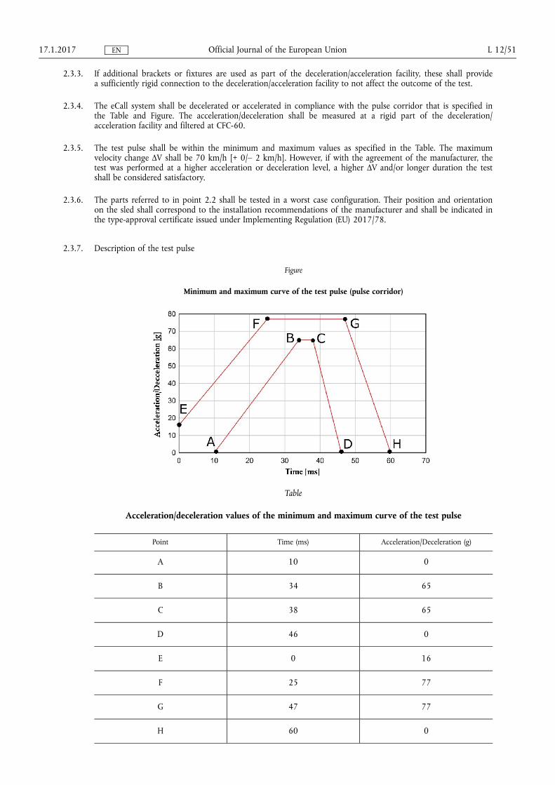
24 Verification procedure
241 Verify that no cable connectors were unplugged during the event
242 The performance requirements shall be verified by performing a test call using the power source subjected to the high-severity deceleration
243 Before performing the test call ensure that
(a) the eCall system receives (real or simulated) GNSS signals to an extent representative of open sky conditions
(b) the eCall system has had sufficient time in a powered state to achieve a GNSS position fix
(c) one of the connection procedures defined in point 27 as agreed between the technical service and the manufacturer will be applied for any test call
(d) the dedicated PSAP test point is available to receive an eCall emitted by the 112-based system
(e) a false eCall to a genuine PSAP cannot be made over the live network and
(f) if applicable the TPS system is deactivated or will automatically switch to the 112-based system
244 Perform a test call (push mode) by applying a trigger according to the instructions of the manufacturer
245 Verify each of the following items
(a) Verify that an MSD was received by the PSAP test point This shall be verified by a record of the PSAP test point showing that an MSD emitted from the eCall system following the trigger was received and successfully decoded If the MSD decoding failed at redundancy version MSD rv0 but was successful at a higher redundancy version or in robust modulator mode as defined in ETSITS 126 267 this is acceptable
(b) Verify that the MSD contained an up-to-date timestamp This shall be verified by a test record showing that the timestamp contained in the MSD received by the PSAP test point does not deviate from the exact recorded time of the trigger activation by more than 60 seconds The transmission may be repeated if the eCall system failed to achieve a GNSS position fix before the test
(c) Verify that the MSD contained an accurate up-to-date location This shall be verified in accordance with the Vehicle Location Test Procedure as defined in point 25 by a test record showing that the deviation between IVS location and true location d_IVS is less than 150 metres and the confidence bit transmitted to the PSAP test point indicates position can be trusted
246 Clear down the test call using the appropriate PSAP test point command (eg hang up)
25 Positioning test procedure
251 The sustained functionality of the GNSS components shall be verified by comparing the location input and the location output of the system
252 The lsquoIVS locationrsquo (φIVS λIVS) shall be The location contained in an MSD transmitted to a PSAP test point while the GNSS antenna is in open sky conditions (real or simulated)
253 The lsquotrue locationrsquo (φtrue λtrue) shall be
(a) the actual location of the GNSS antenna (known location or determined with another means than the eCall system) when using real GNSS signals or
(b) the simulated location when using simulated GNSS signals
1712017 L 1252 Official Journal of the European Union EN
254 The deviation between IVS location and true location dIVS shall be calculated using the following equations
Δφ = φIVS ndash φtrue
Δλ = λIVS ndash λtrue
φm frac14φIVS thorn φtrue
2
dIVS frac14 R ffiffiffiffiffiffiffiffiffiffiffiffiffiffiffiffiffiffiffiffiffiffiffiffiffiffiffiffiffiffiffiffiffiffiffiffiffiffiffiffiffiffi
ethΔφTHORN2
thorn ethcosethφmTHORNΔλTHORN2
q
where
Δφ Difference in latitude (in radian)
Δλ Difference in longitude (in radian)
Note 1deg frac14π
180rad 1 mas = 48481368 10ndash 9 rad
φm Mean latitude (in unit suitable for the cosine calculation)
R Radius of the earth (mean) = 6 371 009 metres
255 The positioning test procedure may be repeated if the eCall system failed to achieve a GNSS position fix before the test
26 Antenna test procedure
261 If the connection procedure applied for the test call did not make use of over-the-air data transmission the sustained functionality of the mobile network antenna shall be verified by checking the antenna tuning status after the deceleration event according to the following procedure
262 Measure the voltage standing wave ratio of the external mobile network antenna after the deceleration event at a frequency within the antennas specified frequency band
2621 The measurement shall be performed with a power meter antenna analyser or SWR meter as close as possible to the antenna feed point
2622 If a power meter is used shall be calculated using the following equation
VSWR frac14
ffiffiffiffiPf
pthorn
ffiffiffiffiPr
p
ffiffiffiffiPf
p minus
ffiffiffiffiPr
p
where
Pf Forward measured power
Pr Reversereflected measured power
263 Verify that satisfies the specifications prescribed by the manufacturer for new antennas
27 Connection procedures
271 Simulated Mobile Network Procedure
2711 It shall be ensured that a TS12 call emitted by the 112-based system will be performed over-the-air via a non-public (ie simulated) mobile network and routed to the dedicated PSAP test point
2712 The dedicated PSAP test point during the test procedures shall be a PSAP simulator under the control of the technical service compliant with the applicable EN standards and certified in accordance with EN 16454 It shall be equipped with an audio interface to allow voice communication tests
1712017 L 1253 Official Journal of the European Union EN
2713 If applicable it shall be ensured that a TS11 call emitted by the TPS system will be performed over-the-air via a non-public (ie simulated) mobile network and routed to the TPSP test point
2714 The TPSP test point shall be a dedicated TPSP answering point simulator under the control of the technical service or a genuine TPSP answering point (permission by TPSP required)
2715 Mobile network coverage of at least ndash 99 dBm or equivalent is recommended for this procedure
272 Public Mobile Network Procedure
2721 It shall be ensured that a TS11 call to a long number will be emitted by the 112-based system (instead of a TS12 call) and will be performed over-the-air via a public mobile network and routed to the dedicated PSAP test point
2722 The dedicated PSAP test point during the test procedures shall be a PSAP simulator under the control of the technical service compliant with the applicable EN standards and certified in accordance with EN 16454 It shall be equipped with an audio interface to allow voice communication tests
2723 If applicable it shall be ensured that a TS11 call emitted by the TPS system will be performed over-the-air via a public mobile network and routed to the TPSP test point
2724 The TPSP test point shall be a dedicated TPSP answering point simulator under the control of the technical service or a genuine TPSP answering point (permission by TPSP required)
2725 Mobile network coverage of at least ndash 99 dBm or equivalent is recommended for this procedure
273 Wired Transmission Procedure
2731 It shall be ensured that a TS12 call emitted by the 112-based system will only be performed via a wired connection with a dedicated network simulator (bypassing any mobile network antenna) and routed to the dedicated PSAP test point
2732 The dedicated PSAP test point during the test procedures shall be a PSAP simulator under the control of the technical service compliant with the applicable EN standards and certified in accordance with EN 16454 It shall be equipped with an audio interface to allow voice communication tests
2733 If applicable it shall be ensured that a TS11 call emitted by the TPS system will be performed via a wired connection with a dedicated network simulator (bypassing any mobile network antenna) and routed to the dedicated TPSP test point
2734 The TPSP test point shall be a dedicated TPSP answering point simulator under the control of the technical service or a genuine TPSP answering point (permission by TPSP required)
28 Verification procedures for components
281 These procedures shall apply for the purposes of type-approval of a 112-based eCall in-vehicle system component in accordance with Article 5 of this Regulation
2811 These procedures shall apply after the individual parts are subjected to the deceleration test under point 23 of this Annex
282 Control module including its connectors and wire harness as described in point 224 of this Annex
2821 Verify that no cable connectors are unplugged during the event
2822 The performance requirements shall be verified by performing a test call
1712017 L 1254 Official Journal of the European Union EN
2823 Before performing the test call ensure that
(a) the eCall system receives (real or simulated) GNSS signals to an extent representative of open sky conditions
(b) the eCall system has had sufficient time in a powered state to achieve a GNSS position fix
(c) one of the connection procedures defined in point 27 as agreed between the technical service and the manufacturer will be applied for any test call
(d) the dedicated PSAP test point is available to receive an eCall emitted by the 112-based system
(e) a false eCall to a genuine PSAP cannot be made over the live network and
(f) if applicable the TPS system is deactivated or will automatically switch to the 112-based system
2824 Perform a test call (push mode) by applying a trigger according to the instructions of the manufacturer
2825 Verify each of the following items
(a) Verify that an MSD was received by the PSAP test point This shall be verified by a record of the PSAP test point showing that an MSD emitted from the eCall system following the trigger was received and successfully decoded If the MSD decoding failed at redundancy version MSD rv0 but was successful at a higher redundancy version or in robust modulator mode as defined in ETSITS 126 267 this is acceptable
(b) Verify that the MSD contained an up-to-date timestamp This shall be verified by a test record showing that the timestamp contained in the MSD received by the PSAP test point does not deviate from the exact recorded time of the trigger activation by more than 60 seconds The transmission may be repeated if the eCall system failed to achieve a GNSS position fix before the test
(c) Verify that the MSD contained an accurate up-to-date location This shall be verified in accordance with the Vehicle Location Test Procedure as defined in point 25 by a test record showing that the deviation between IVS location and true location dIVS is less than 150 metres and the confidence bit transmitted to the PSAP test point indicates lsquoposition can be trustedrsquo
2826 Clear down the test call using the appropriate PSAP test point command (eg hang up)
283 Mobile network antenna including its connectors and wire harness as described in point 224 of this Annex
2831 Verify that no cable connectors were unplugged during the event
2832 Measure the voltage standing wave ratio VSWR of the external mobile network antenna after the deceleration event at a frequency within the antennas specified frequency band
2833 The measurement shall be performed with a power meter antenna analyser or SWR meter as close as possible to the antenna feed point
2834 If a power meter is used VSWR shall be calculated using the following equation
VSWR frac14
ffiffiffiffiPf
pthorn
ffiffiffiffiPr
p
ffiffiffiffiPf
p minus
ffiffiffiffiPr
p
where
Pf Forward measured power
Pr Reversereflected measured power
2835 Verify that VSWR satisfies the specifications prescribed by the manufacturer for new antennas
1712017 L 1255 Official Journal of the European Union EN
284 Power supply (if not part of the control module) including its connectors and wire harness as described in point 224 of this Annex
2841 Verify that no cable connectors are unplugged during the event
2842 Measure if the voltage corresponds to the manufacturers specification
1712017 L 1256 Official Journal of the European Union EN
ANNEX II
Full-scale impact test assessment
1 Requirements
11 Performance requirements
111 The full-scale impact assessment of vehicles with eCall in-vehicle systems installed carried out in accordance with point 2 shall be considered satisfactory if the following requirements are demonstrated post-impact
112 Automatic triggering The eCall system shall automatically initiate an eCall after an impact in accordance with UN Regulation No 94 (Annex 3) as well as UN Regulation No 95 (Annex 4) as applicable
113 Call status indication The eCall system shall inform the occupants about the current status of the eCall (status indicator) using a visual andor audible signal
114 MSD emission and encoding The eCall system shall be able to successfully transmit an MSD to a PSAP test point via the mobile network
115 Vehicle-specific data determination The eCall system shall be able to populate accurately the mandatory vehicle- specific data fields of the MSD
116 Position determination The eCall system shall be able to determine accurately the up-to-date vehicle location
2 Test procedure
21 Purpose of the full-scale impact test procedure
The purpose of this test is to verify the automatic triggering function and the sustained functionality of the 112-based eCall in-vehicle system in vehicles that are subjected to a frontal impact or a side impact
22 The following tests shall be performed on a vehicle with an eCall in-vehicle system installed
23 Impact test procedure
231 Impact tests shall be carried out in accordance with the tests defined in UN Regulation No 94 Annex 3 for frontal impact as well as UN Regulation No 95 Annex 4 for side impact as applicable
232 The test conditions defined in UN Regulation No 94 or UN Regulation No 95 shall apply
233 Before performing the impact tests ensure that
(a) the in-vehicle power source if installed for the test is charged according to the specifications of the manufacturer at the beginning of the test to allow performing the subsequent verification tests
(b) the automatic eCall is enabled and armed and that the vehicle ignition or master control switch is activated
(c) one of the connection procedures defined in point 27 as agreed between the technical service and the manufacturer will be applied for any test call
(d) the dedicated PSAP test point is available to receive an eCall emitted by the 112-based system
(e) a false eCall to a genuine PSAP cannot be made over the live network and
(f) if applicable the TPS system is deactivated or will automatically switch to the 112-based system
24 Verification procedure
241 The performance requirements shall be verified by performing a test call from the vehicle after the impact using the 112-based eCall in-vehicle system An automatically triggered eCall following the impact test
242 Perform a test call (push mode) by applying an automatic trigger
1712017 L 1257 Official Journal of the European Union EN
243 Verify each of the following items in at least one of the test calls
(a) Verify that an eCall was triggered automatically by the full-scale impact event This shall be verified by a record of the PSAP test point showing that it received an eCall initiation signal following the impact event and that the MSD control indicator was set to lsquoautomatically initiated eCallrsquo
(b) Verify that the eCall status indicator indicated an eCall sequence following the automatic or manual trigger This shall be verified by a record showing that an indication sequence was performed on all sensory channels specified in the manufacturers documentation (visual andor audible)
(c) Verify that an MSD was received by the PSAP test point This shall be verified by a record of the PSAP test point showing that an MSD emitted from the vehicle following the automatic or manual trigger was received and successfully decoded If the MSD decoding failed at redundancy version MSD rv0 but was successful at a higher redundancy version or in robust modulator mode as defined in ETSITS 126 267 this is acceptable
(d) Verify that the MSD contained accurate vehicle-specific data This shall be verified by a record of the PSAP test point showing that the information transmitted in the fields regarding vehicle type vehicle identification number (VIN) and vehicle propulsion storage type does not deviate from the information specified in the type-approval application
(e) Verify that the MSD contained an accurate up-to-date location This shall be verified in accordance with the Vehicle Location Test Procedure as defined in point 25 of Annex I to this Regulation by a test record showing that the deviation between IVS location and true location d_IVS is less than 150 metres and the confidence bit transmitted to the PSAP test point indicates lsquoposition can be trustedrsquo If no GNSS signals are available at the impact test location the vehicle can be moved to an appropriate location before performing the test call
244 Clear down the test call using the appropriate PSAP test point command (eg hang up)
245 If the automatic test call could not be performed successfully due to vehicle-external factors it shall be permissible to verify the automatic trigger following the impact via the internal record transaction function of the in-vehicle system This register shall be capable to store received trigger signals in non-volatile memory The test engineer shall have access to the data stored in the in-vehicle system and shall verify that no record of automatic trigger signal is stored before the impact event and that a record of an automatic trigger signal is stored after the impact event
246 If the test call was performed with the vehicle connected to an off-vehicle power supply (in cases where the impact test was carried out with the standard vehicle power supply not installed) verify that the on-board electrical system feeding the eCall in-vehicle system remained intact This shall be verified by a record of a test engineer confirming a successful check of the integrity of the on-board electrical system including the dummy in-vehicle power source (visual inspection for mechanical damage to either the power sources mounting bracket or its structure) and the connections via its terminals
25 Positioning test procedure
The positioning test procedure defined in point 25 of Annex I to this Regulation shall apply
26 Antenna test procedure
261 If the connection procedure applied for the test call did not make use of over-the-air data transmission (point 273 of Annex I to this Regulation) the sustained functionality of the mobile network antenna shall be verified by checking the antenna tuning status after the full-scale impact test according to the procedure defined in point 26 of Annex I to this Regulation In addition it shall be verified that no wire breakage or short-circuit of the antenna feed line occurred by checking the electrical resistance between the end points of the wire and between the wire and vehicle ground
27 Connection procedures
The connection procedures defined in point 27 of Annex I to this Regulation shall apply
1712017 L 1258 Official Journal of the European Union EN
ANNEX III
Crash resistance of audio equipment
1 Requirements
11 Performance requirements
111 The assessment of the crash resistance of the eCall audio equipment of vehicles with eCall in-vehicle systems installed carried out in accordance with point 2 shall be considered satisfactory if the following requirements are demonstrated post-impact as regards the frontal impact test as well as the side impact test as applicable
112 Reconnection of audio equipment The eCall system shall reconnect the loudspeaker(s) and microphone(s) after being disconnected during an eCall for MSD transmission
113 Voice communication The eCall system shall allow hands-free voice communication (send and receive direction) of sufficient intelligibility between vehicle occupants and an operator
2 Test procedure
21 Purpose of the audio equipment crash resistance test procedure
The purpose of this test is to verify that loudspeaker(s) and microphone(s) are successfully reconnected after being disconnected for MSD transmission and that the audio equipment remained functional after the vehicle has been subjected to the frontal impact or the side impact test
22 The following verification test shall be performed on a vehicle with the eCall in-vehicle system installed that has been subjected to a full-scale impact according to Regulation No 94 Annex 3 for frontal impact or UN Regulation No 95 Annex 4 for side impact as set out in point 111 above
23 Overview of test procedure
231 The sustained functionality of the audio equipment shall be verified by performing a test call after the impact test and using the voice communication channel between the vehicle and the PSAP test point
232 Two test engineers positioned in the vehicle (near-end tester) and at the PSAP test point (far-end tester) respectively successively transmit (read and listen) pre-defined phonetically balanced sentences in single talk mode
233 The testers are required to assess whether they were able to understand the meaning of the transmission in the send and receive directions
24 Arrangement of testers
241 The test shall be performed in a quiet environment with a background noise level of not more than 50 dB(A) and that is free from any noise sources that might otherwise disrupt the tests
242 The near-end tester shall be positioned so that his head is close to a normal seating position on the drivers seat of the impacted vehicle The tester shall use the in-vehicle audio equipment in the original arrangement
243 The far-end tester shall be positioned away from the vehicle with sufficient separation so that speech in normal loudness from one tester cannot be understood without any aids by the other tester
25 Test setup
251 Before performing the test call ensure that
(a) one of the connection procedures defined in point 27 of Annex I to this Regulation as agreed between technical service and manufacturer will be applied for any test call
(b) the dedicated PSAP test point is available to receive an eCall emitted by the 112-based system
1712017 L 1259 Official Journal of the European Union EN
(c) a false eCall to a genuine PSAP cannot be made over the live network
(d) if applicable the TPS system is deactivated or will automatically switch to the 112-based system and
(e) the vehicle ignition or master control switch is activated
252 Where it is possible to adapt the volume setting the maximum volume control setting in send and receive direction at the near-end and at the far-end shall be chosen The volume control settings at the far-end may be decreased during the test if required for better intelligibility
253 If possible no mobile networks that have an influence on the hands-free performance (eg echo AGC noise reduction etc) should be chosen for the connection For simulated networks if possible DTX shall be switched off the full rate codec shall be used (for GSM standard) and the highest bit rate of 122 kbits shall be used (for AMR codecs)
26 Test call
261 Perform a test call (push mode) by applying a manual trigger via the in-vehicle HMI and wait until the loudspeaker(s) and microphone(s) are reconnected for voice communication after completed MSD transmission
262 Exchange of test messages
2621 Receive direction
26211 The far-end tester shall select and read one sentence pair of the list provided in the Appendix The tester shall read the sentences in a normal volume as used in phone calls
26212 The near-end tester shall assess whether the voice transmission in the receive direction was intelligible The test in receive direction is passed if the near-end tester resting in his original seating position was able with any feasible effort to understand the full meaning of the transmission
26213 If required for the assessment the near-end tester can request from the far-end tester to transmit additional sentence pairs
2622 Send direction
26221 The near-end tester shall select and resting in his original seating position read one sentence pair of the list provided in the Appendix The tester shall read the sentences in a normal volume as used in phone calls
26222 The far-end tester shall assess whether the voice transmission in the send direction was intelligible The test in send direction is passed if the far-end tester was able with any feasible effort to understand the full meaning of the transmission
26223 If required for the assessment the far-end tester can request from the near-end tester to transmit additional sentence pairs
263 Clear down the test call using the appropriate PSAP test point command (eg hang up)
264 If the requirements cannot be fulfilled due to impairments introduced by the PSAP test point or the transmission medium the test call may be repeated if required in an adapted test setup
27 Connection procedures
271 The connection procedures defined in point 27 of Annex I to this Regulation shall apply
1712017 L 1260 Official Journal of the European Union EN
Appendix
Test sentences
1 The following test sentence pairs as defined in ITU-T P501 Annex B shall be used for the exchange of test messages in the send and receive directions
2 Test sentence pairs in the language most commonly spoken by the testers shall be selected from the list below If the testers are not familiar with any of the languages alternative sentences in a familiar language preferably phonetically balanced shall be used
3 Test sentence pairs
31 Dutch
(a) Dit product kent nauwelijks concurrentie
Hij kende zijn grens niet
(b) Ik zal iets over mijn carriegravere vertellen
Zijn auto was alweer kapot
(c) Zij kunnen de besluiten nehmen
De meeste mensen hadden het wel door
(d) Ik zou liever gaan lopen
Willem gaat telkens naar buiten
32 English
(a) These days a chicken leg is a rare dish
The hogs were fed with chopped corn and garbage
(b) Rice is often served in round bowls
A large size in stockings is hard to sell
(c) The juice of lemons makes fine punch
Four hours of steady work faced us
(d) The birch canoe slid on smooth planks
Glue the sheet to the dark blue background
33 Finnish
(a) Ole aumlaumlneti tai sano sellaista joka on parempaa kuin vaikeneminen
Suuret sydaumlmet ovat kuin valtameret ne eivaumlt koskaan jaumlaumldy
(b) Jos olet vasara lyouml kovaa Jos olet naula pidauml paumlaumlsi pystyssauml
Onni tulee elaumlen ei ostaen
(c) Rakkaus ei omista mitaumlaumln eikauml kukaan voi sitauml omistaa
Naisen mieli on puhtaampi haumln vaihtaa sitauml useammin
(d) Sydaumlmellauml on syynsauml joita jaumlrki ei tunne
On opittava kaumlrsimaumlaumln voidakseen elaumlauml
1712017 L 1261 Official Journal of the European Union EN
34 French
(a) On entend les gazouillis dun oiseau dans le jardin
La barque du pecirccheur a eacuteteacute emporteacutee par une tempecircte
(b) Le client sattend agrave ce que vous fassiez une reacuteduction
Chaque fois que je me legraveve ma plaie me tire
(c) Vous avez du plaisir agrave jouer avec ceux qui ont un bon caractegravere
Le chevrier a corneacute pour rassembler ses moutons
(d) Ma megravere et moi faisons de courtes promenades
La poupeacutee fait la joie de cette tregraves jeune fille
35 German
(a) Zarter Blumenduft erfuumlllt den Saal
Wisch den Tisch doch spaumlter ab
(b) Sekunden entscheiden uumlber Leben
Flieder lockt nicht nur die Bienen
(c) Gegen Dummheit ist kein Kraut gewachsen
Alles wurde wieder abgesagt
(d) Uumlberquere die Strasse vorsichtig
Die drei Maumlnner sind begeistert
36 Italian
(a) Non bisogna credere che sia vero tutto quello che dice la gente Tu non conosci ancora gli uomini non conosci il mondo
Dopo tanto tempo non ricordo piugrave dove ho messo quella bella foto ma se aspetti un po la cerco e te la prendo
(b) Questo tormento dureragrave ancora qualche ora Forse un giorno poi tutto finiragrave e tu potrai tornare a casa nella tua terra
Lucio era certo che sarebbe diventato una persona importante un uomo politico o magari un ministro Aveva a cuore il bene della societagrave
(c) Non bisogna credere che sia vero tutto quello che dice la gente tu non conosci ancora gli uomini non conosci il mondo
Dopo tanto tempo non ricordo piugrave dove ho messo quella bella foto ma se aspetti un po la cerco e te la prendo
(d) Questo tormento dureragrave ancora qualche ora Forse un giorno poi tutto finiragrave e tu potrai tornare a casa nella tua terra
Lucio era certo che sarebbe diventato una persona importante un uomo politico o magari un ministro aveva a cuore il bene della societagrave
37 Polish
(a) Pielęgniarki były cierpliwe
Przebiegał szybko przez ulicę
(b) Ona była jego sekretarką od lat
Dzieci często płaczą kiedy są głodne
1712017 L 1262 Official Journal of the European Union EN
(c) On był czarującą osobą
Lato wreszcie nadeszło
(d) Większość droacuteg było niezmiernie zatłoczonych
Mamy bardzo entuzjastyczny zespoacuteł
38 Spanish
(a) No arroje basura a la calle
Ellos quieren dos manzanas rojas
(b) No cocinaban tan bien
Mi afeitadora afeita al ras
(c) Ve y sieacutentate en la cama
El libro trata sobre trampas
(d) El trapeador se puso amarillo
El fuego consumioacute el papel
1712017 L 1263 Official Journal of the European Union EN
ANNEX IV
Co-existence of third party services (TPS) with the 112-based eCall in-vehicle systems
1 Requirements
11 The following requirements apply to 112-based eCall in-vehicle systems STUs and (optionally for) components that shall be used in conjunction with a TPS eCall in-vehicle system
12 Performance requirements
121 The 112-based system shall be deactivated as long as the TPS system is active and does function
122 The 112-based system shall be automatically triggered in the event that the TPS system is triggered but does not function
13 Documentation requirements
131 The manufacturer shall provide the technical service with an explanation of the design provisions built into the TPS system to ensure automatic triggering of the 112-based system (lsquofall-back procedurersquo) in the event that the TPS system does not function This documentation shall describe the principles of the changeover mechanism
132 The documentation shall be supported by an analysis which shows in overall terms any hardware or software failure conditions that would result in an inability of the TPS system to perform a successful call and how the TPS system will behave on the occurrence of these
This may be based on a Failure Mode and Effect Analysis (FMEA) a Fault Tree Analysis (FTA) or any appropriate similar process as agreed between the technical service and the manufacturer
The chosen analytical approach(es) shall be established and maintained by the manufacturer and shall be made open for inspection by the technical service at the time of the type-approval
2 Test procedure
21 Purpose of the TPS co-existence test procedure
The purpose of this test procedure is to verify for eCall in-vehicle systems that shall be used in conjunction with a TPS eCall in-vehicle system that there is only one system active at a time and that the 112-based system is triggered automatically in the event that the TPS system does not function
22 The following tests shall be performed either on a vehicle with an eCall in-vehicle system installed or on a repshyresentative arrangement of parts
23 The deactivation of the 112-based system while the TPS system is active shall be verified by performing a manually triggered test call
231 Before performing the test call ensure
(a) that one of the connection procedures defined in point 27 of Annex I to this Regulation as agreed between the technical service and the manufacturer will be applied for any test call
(b) that the dedicated PSAP test point is available to receive an eCall emitted by the 112-based system
(c) that the TPSP test point is available to receive a call emitted by the TPS system
(d) that a false eCall to a genuine PSAP cannot be made over the live network and
(e) that the vehicle ignition or master control switch is activated
232 Perform a test call by applying a manual trigger of the TPS system (push mode)
1712017 L 1264 Official Journal of the European Union EN
233 Verify
(a) that a call was established with the TPSP test point by a record of the TPSP test point showing that it did receive a call initiation signal or by a successful voice connection to the TPSP test point and
(b) that no eCall was attempted or established with the PSAP test point by a record of the PSAP test point showing that it did not receive an eCall initiation signal
234 Clear down the test call using the appropriate PSAP test point command (eg hang up)
235 If the call attempt of the TPS system fails during the test the test procedure may be repeated
24 The fall-back procedure shall be verified by performing a manually triggered test call to a dedicated PSAP test point in a condition where the TPS system does not function
241 Modify the TPS system to simulate a failure selected at the discretion of the type-approval authority that shall result in a fall-back procedure based on the documentation provided by the manufacturer
242 Before performing the test call ensure
(a) that one of the connection procedures defined in point 27 of Annex I to this Regulation as agreed between the technical service and the manufacturer will be applied for any test call
(b) that the dedicated PSAP test point is available to receive an eCall emitted by the 112-based system
(c) that a false eCall to a genuine PSAP cannot be made over the live network and
(d) that the vehicle ignition or master control switch is activated
243 Perform a test call by applying a manual trigger of the TPS system (push mode)
244 Verify that an eCall was established by the 112-based system by a record of the PSAP test point showing that it did receive an eCall initiation signal
245 Clear down the test call using the appropriate PSAP test point command (eg hang up)
25 Connection procedures
The connection procedures defined in point 27 of Annex I to this Regulation shall apply
1712017 L 1265 Official Journal of the European Union EN
ANNEX V
Automatic triggering mechanism
1 Requirements
11 The following requirements apply to vehicles with eCall in-vehicle systems installed
12 Documentation requirements
121 The manufacturer shall provide a statement which affirms that the strategy chosen to trigger an automatic eCall ensures triggering also in accident configurations dissimilar from andor of a lower severity than the collisions simulated in the applicable full-scale crash tests in UN Regulation No 94 and UN Regulation No 95
122 The manufacturer shall choose the collision typology and severity and will demonstrate that it is significantly different than the full-scale crash tests
123 The manufacturer shall provide the type-approval authority with an explanation and technical documentation which shows in overall terms how this is achieved
1231 Documentation that shows to the satisfaction of the type-approval authority that the activation of supplemental restraint systems and the severity level chosen at the discretion of the manufacturer also induces an automatic eCall shall be considered satisfactory
1232 Documentation that shows to the satisfaction of the type-approval authority the strategy to prevent unjustified eCalls from being made in case of impacts of a severity level that is not considered a severe accident Moreover failure mode analysis shall be provided which shows that any hardware or software faults shall not result in automatic triggering of an eCall
1233 Airbag control unit specification drawings specification data notes sensitivity drawings relevant circuit diagrams or similar documents considered equivalent by the type-approval authority would be suitable means to demonstrate this connection
1234 The extended documentation package shall remain strictly confidential It may be kept by the approval authority or at the discretion of the approval authority may be retained by the manufacturer In case the manufacturer retains the documentation package that package shall be identified and dated by the approval authority once reviewed and approved It shall be made available for inspection by the approval authority at the time of approval or at any time during the validity of the approval
1712017 L 1266 Official Journal of the European Union EN
ANNEX VI
Technical requirements for compatibility of eCall in-vehicle systems with the positioning services provided by the Galileo and the EGNOS systems
1 Requirements
11 Compatibility requirements
111 The lsquoGalileo system compatibilityrsquo shall be the reception and processing of the signals from the Open Service of Galileo using it in the computation of the final position
112 The lsquoEGNOS system compatibilityrsquo shall be the reception of the corrections from the Open Service of EGNOS and its application to the GNSS signals in particular GPS
113 The compatibility of the eCall in-vehicle systems with the positioning services provided by the Galileo and the EGNOS systems shall be compliant with respect to positioning capabilities in section 12 and demonstrated by performing the test methods in section 2
114 The testing procedures in section 22 can be performed either on the eCall unit including post processing ability or directly on the GNSS receiver being a part of the eCall
12 Performance requirements
121 The GNSS receiver shall be able to output the navigation solution in a NMEA-0183 protocol format (RMC GGA VTG GSA and GSV message) The eCall setup for NMEA-0183 messages output shall be described in the operation manual
122 The GNSS receiver being a part of the eCall shall be capable of receiving and processing individual GNSS signals in L1E1 band from at least two global navigation satellite systems including Galileo and GPS
123 The GNSS receiver being a part of the eCall shall be capable of receiving and processing combined GNSS signals in L1E1 band from at least two global navigation satellite systems including Galileo and GPS and SBAS
124 The GNSS receiver being a part of the eCall shall be able to provide positioning information in WGS-84 coordinate system
125 Horizontal position error shall not exceed
mdash under open sky conditions 15 metres at confidence level 095 probability with Position Dilution of Precision (PDOP) in the range from 20 to 25
mdash in urban canyon conditions 40 metres at confidence level 095 probability with Position Dilution of Precision (PDOP) in the range from 35 to 40
126 The specified requirements for accuracy shall be provided
mdash at speed range from 0 to [140] kmh
mdash linear acceleration range from 0 to [2] G
127 Cold start time to first fix shall not exceed
mdash 60 seconds for signal level down to minus 130 dBm
mdash 300 seconds for signal level down to minus 140 dBm
128 GNSS signal re-acquisition time after block out of 60 seconds at signal level down to minus 130 dBm shall not exceed 20 seconds after recovery of the navigation satellite visibility
1712017 L 1267 Official Journal of the European Union EN
129 Sensitivity at receiver input shall be
mdash GNSS signals detection (cold start) do not exceed 3 600 seconds at signal level on the antenna input of the eCall of minus 144 dBm
mdash GNSS signals tracking and navigation solution calculation is available for at least 600 seconds at signal level on the antenna input of the eCall of minus 155 dBm
mdash Re-acquisition of GNSS signals and calculation of the navigation solution is possible and does not exceed 60 seconds at signal level on the antenna input of the eCall of minus 150 dBm
1210 The GNSS receiver shall be able to obtain a position fix at least every second
2 Test methods
21 Test conditions
211 The test object is the eCall which includes a GNSS receiver and a GNSS antenna specifying navigation characshyteristics and features of the tested system
212 The number of the eCall test samples shall be at least 3 pieces and can be tested in parallel
213 The eCall is provided for the test with the installed SIM-card operation manual and the software (provided on electronic media)
214 The attached documents shall contain the following data
mdash device serial number
mdash hardware version
mdash software version
mdash device provider identification number
mdash relevant technical documentation to perform the tests
215 Tests are carried out in normal climatic conditions in accordance with standard ISO 16750-12006
mdash air temperature 23 (plusmn 5) degC
mdash relative air humidity of 25 to 75
216 Tests of the eCall in respect of its GNSS receiver shall be performed with the test and auxiliary equipment specified in Table 1
Table 1
Recommended list of measurement instruments test and auxiliary equipment
Equipment name Required technical characteristics of test equipment
Scale range Scale accuracy
Global navigation satellite system simulator of Galishyleo and GPS signals
Number of simulated signals at least 12
Mean square deviation of random accushyracy component of pseudo-range to Galileo and GPS satellites not more than
mdash stadiometric code phase 01 metres
mdash communication carrier phase 0001 metres
mdash pseudovelocity 0005 metressecshyond
Digital stopwatch Maximum count volume 9 hours 59 minutes 5999 seconds
Daily variation at 25 (plusmn 5) degС not more than 10 seconds
Time discreteness 001 seconds
1712017 L 1268 Official Journal of the European Union EN
Equipment name Required technical characteristics of test equipment
Scale range Scale accuracy
Vector network analyser Frequency range 300 kHz 4 000 kHz
Dynamic range
(minus 85 40) dB
Accuracy F = plusmn 1middot10ndash 6 kHz
Accuracy D = (01 05) dB
Low-noise amplifier Frequency range 1 200 1 700 MHz
Noise coefficient not more 20 dB
Amplifier gain coefficient 24 dB
Attenuator 1 Dynamic range (0 11) dB Accuracy plusmn 05 dB
Attenuator 2 Dynamic range (0 110) dB Accuracy plusmn 05 dB
Power source Range of direct current voltage setting from 01 to 30 volts
Accuracy V = plusmn 3
Current intensity of output voltage at least 3 amperes
Accuracy A = plusmn 1
Note it is allowed to apply other similar types of equipment providing determination of characteristics with the required accuracy
217 Unless otherwise specified GNSS signal simulation shall follow lsquoOpen skyrsquo pattern as shown in Figure 1
Figure 1
Open sky definition
Zone Elevation range (degrees) Azimuth range (degrees)
A 0 ndash 5 0 ndash 360
Background Area out of Zone A
1712017 L 1269 Official Journal of the European Union EN
218 Open Sky plot mdash Attenuation
0 dB
A ndash 100 dB or signal is switched off
22 Test procedures
221 NMEA-0183 messages output test
2211 Make connections according to Figure 2
Figure 2
Diagram of test stand
2212 Prepare and turn on the eCall By means of operation manual and developer software set up the GNSS receiver for receiving signals from Galileo GPS and SBAS Set up the GNSS receiver to output NMEA-0183 messages (messages RMC GGA VTG GSA and GSV)
2213 Set up the simulator according to the simulator user guide Initialize simulator script with the parameters given in Table 2 for Galileo GPS and SBAS signals
Table 2
Main parameters of simulation script for static scenario
Simulated parameter Value
Test duration hhmmss 010000
Output frequency 1 hertz
eCall location Any specified land point between latitude range 80degN and 80degS in coordishynate system WGS-84
Troposphere Standard predefined model by the GNSS simulator
Ionosphere Standard predefined model by the GNSS simulator
PDOP value in the test interval 20 le PDOP le 25
Simulated signals mdash Galileo (E1 frequency band OS)
mdash GPS (L1 frequency band CA code)
mdash combined GalileoGPSSBAS
1712017 L 1270 Official Journal of the European Union EN
Simulated parameter Value
Signal strength
mdash GNSS Galileo minus 135 dBm
mdash GNSS GPS minus 1385 dBm
Number of simulated satellites mdash at least 6 Galileo satellites
mdash at least 6 GPS satellites
mdash at least 2 SBAS satellites
2214 By means of corresponding serial interface set the connection between the eCall and PC Control the possibility of receiving navigation information via NMEA-0183 protocol The value of field 6 in the GGA messages is set to lsquo2rsquo
2215 Test results are considered successful if navigation information via NMEA-0183 protocol is received in all the eCall samples
2216 The test of NMEA-0183 messages output and the assessment of the positioning accuracy in autonomous static mode can be combined
222 Assessment of positioning accuracy in autonomous static mode
2221 Make connections according to Figure 2
2222 Prepare and turn on the eCall By means of developer software make sure that the GNSS receiver is set up for receiving Galileo GPS and SBAS combined signals Set up the GNSS receiver to output messages according to the NMEA-0183 protocol (GGA RMC VTG GSA and GSV messages)
2223 Set up the simulator in accordance with its operational manual Start simulation of combined Galileo GPS and SBAS signals script with the set parameters given in Table 2
2224 Set up the recording of NMEA-0183 messages after receiving the navigation solution Up to the moment the simulation script is complete the NMEA-0183 messages are output by the GNSS receiver to a file
2225 Upon receiving the navigation solution set up recording of NMEA-0183 messages output by the GNSS receiver to a file up to the moment the simulation script is complete
2226 Extract coordinates latitude (B) and longitude (L) contained in GGA (RMC) messages
2227 Calculate the systematic inaccuracy of coordinates determination on stationary intervals according to formulas (1) (2) for example for latitude coordinate (B)
(1) ΔB(j) = B(j) ndash Btruej
(2) dB frac141N
XN
j frac14 1
ΔBethjTHORN
mdash Btruej is the actual value of B coordinate in j time moment in arc-seconds
mdash B(j) is the determined value of B coordinate in j time moment by the GNSS receiver in arc-seconds
mdash N is the amount of GGA (RMC) messages received during the test of GNSS receiver
2228 Similarly calculate the systematic inaccuracy of L (longitude) coordinate
1712017 L 1271 Official Journal of the European Union EN
2229 Calculate standard deviation (SD) value according to formula (3) for B coordinate
(3) σB frac14
ffiffiffiffiffiffiffiffiffiffiffiffiffiffiffiffiffiffiffiffiffiffiffiffiffiffiffiffiffiffiffiPN
j frac14 1ethΔBethjTHORN minus dBTHORN
2
N minus 1
vuuut
22210 Similarly calculate the SD value for L (longitude) coordinate
22211 Convert calculated coordinates and SD values of latitude and longitude determination from arc-seconds to meters according to formulas (4) ndash (5)
22212 For latitude
(4-1) dBethмTHORN frac14 2 a eth1 minus e2THORN
eth1 minus e2sin2φTHORN3=2 05Prime π
180 3 600Prime dB
(4-2) σBethмTHORN frac14 2 a eth1 minus e2THORN
eth1 minus e2sin2φTHORN3=2 05Prime π
180 3 600Prime σB
22213 For longitude
(5-1) dLethмTHORN frac14 2 a cosφffiffiffiffiffiffiffiffiffiffiffiffiffiffiffiffiffiffiffiffiffi1 minus e2sin2φ
p 05Prime π180 3 600Prime
dL
(5-2) σLethмTHORN frac14 2 a cosφffiffiffiffiffiffiffiffiffiffiffiffiffiffiffiffiffiffiffiffiffi1 minus e2sin2φ
p 05Prime π180 3 600Prime
σL
mdash а mdash Semi-major axis of ellipsoid metres
mdash e mdash first eccentricity [0 ndash 1]
mdash φ mdash determined value of latitude radians
22214 Calculate horizontal position error according to formula (6)
(6) Π frac14ffiffiffiffiffiffiffiffiffiffiffiffiffiffiffiffiffiffiffiffiffiffiffiffiffiffiffiffiffiffiffiffiffiffiffidB2ethmTHORN thorn dL2ethmTHORN
pthorn 2
ffiffiffiffiffiffiffiffiffiffiffiffiffiffiffiffiffiffiffiffiffiffiffiffiffiffiffiffiffi
σ2BethmTHORN thorn σ2
LethmTHORN
q
22215 Repeat test procedures according to 2223 ndash 22214 for GNSS Galileo signals with simulation parameters given in Table 2
22216 Repeat test procedures according to 2223 ndash 22214 only for GPS GNSS signals with simulation parameters given in Table 2
22217 Repeat test procedures according to 2223 ndash 22216 with other eCall samples provided for the test
22218 Determine average values according to (6) obtained for all tested eCall samples
22219 Tests results are considered satisfactory if horizontal position errors as defined by formula (6) obtained with all eCall samples do not exceed 15 metres under open sky conditions at confidence level 095 probability for all simulation scripts
223 Assessment of positioning accuracy in autonomous dynamic mode
2231 Repeat test procedures described in section 222 but 22215 ndash 22216 with simulation script for manoeuvring movement given in Table 3
1712017 L 1272 Official Journal of the European Union EN
Table 3
Main parameters of simulation script for manoeuvring movement
Simulated parameter Value
Test duration hhmmss 010000
Output frequency 1 hertz
eCall location Any specified land point between latitude range 80degN and 80degS in coordishynate system WGS-84
Model of movement Manoeuvring movement
mdash speed kmh 140
mdash turning radius metres 500
mdash turning acceleration metres second2
02
Troposphere Standard predefined model by the GNSS simulator
Ionosphere Standard predefined model by the GNSS simulator
PDOP value in the test time interval
20 le PDOP le 25
Simulated signals Combined GalileoGPSSBAS
Signal strength
mdash GNSS Galileo minus 135 dBm
mdash GNSS GPS minus 1385 dBm
Number of simulated satellites mdash at least 6 Galileo satellites
mdash at least 6 GPS satellites
mdash at least 2 SBAS satellites
2232 Determine average values according to (6) obtained for all tested eCall samples
2233 Tests results are considered satisfactory if horizontal position errors obtained with all eCall samples do not exceed 15 metres under open sky conditions at confidence level 095 probability
1712017 L 1273 Official Journal of the European Union EN
224 Movement in shadow areas areas of intermittent reception of navigation signals and urban canyons
2241 Repeat test procedures described in section 223 for simulation script for movement in shadow areas and areas of intermittent reception of navigation signals (given in Table 4) with an urban canyon signal pattern described in Figure 3
Table 4
Main parameters of movement in shadow areas and areas of intermittent reception of navigation signals
Simulated parameter Value
Test duration hhmmss 010000
Output frequency 1 hertz
eCall location Any specified land point between latitude range 80degN and 80degS in coordishynate system WGS-84
Model of movement Manoeuvring movement
mdash speed kmh 140
mdash turning radius metres 500
mdash turning acceleration metres second2
02
Satellite visibility
mdash signal visibility intervals seconds
300
mdash signal absence intervals secshyonds
600
Troposphere Standard predefined model by the GNSS simulator
Ionosphere Standard predefined model by the GNSS simulator
PDOP value in the test time inshyterval
35 le PDOP le 40
Simulated signals Combined GalileoGPSSBAS
Signal strength
mdash GNSS Galileo minus 135 dBm
mdash GNSS GPS minus 1385 dBm
Number of simulated satellites mdash at least 6 Galileo satellites
mdash at least 6 GPS satellites
mdash at least 2 SBAS satellites
1712017 L 1274 Official Journal of the European Union EN
Figure 3
Urban canyon definition
Zone Elevation range (degrees) Azimuth range (degrees)
A 0 ndash 5 0 ndash 360
B 5 ndash 30 210 ndash 330
C 5 ndash 30 30 ndash 150
Background Area out of Zone A B C
2242 Urban canyon plot- Attenuation
0 dB
B ndash 40 dB
C ndash 40 dB
A ndash 100 dB or signal is switched off
2243 Tests results are considered satisfactory if horizontal position errors obtained with all eCall samples do not exceed 40 metres in urban canyon conditions at confidence level 095 probability
225 Cold start time to first fix test
2251 Prepare and turn on the eCall By means of developer software make sure that GNSS module is set to receive Galileo and GPS signals
2252 Delete all position velocity time almanac and ephemeris data from the GNSS receiver
1712017 L 1275 Official Journal of the European Union EN
2253 Set up the simulator according to the simulator user guide Initialize simulator script with the parameters given in Table 2 for Galileo and GPS signals with signal level minus 130 dBm
2254 By means of a stopwatch measure time interval between signal simulation start and the first navigation solution result
2255 Conduct test procedures according to 2252 ndash 2254 at least 10 times
2256 Calculate average time to first fix in cold start mode based on measurements for all eCall samples provided for the test
2257 The test result is considered to be positive if average values of time to first fix calculated as described in 2256 do not exceed 60 seconds for signal level down to minus 130 dBm for all the simulated signals
2258 Repeat test procedure according to 2251 ndash 2255 with signal level minus 140 dBm
2259 The test result according to 2258 is considered to be positive if average values of time to first fix calculated as described in 2256 do not exceed 300 seconds for signal level down to minus 140 dBm for all the simulated signals
226 Test of re-acquisition time of tracking signals after block out of 60 seconds
2261 Prepare and turn on the eCall according to operational manual By means of the developer software make sure that GNSS receiver is set up to receive Galileo and GPS signals
2262 Set up the simulator according to the simulator user guide Initialize simulator script with the parameters given in Table 2 for Galileo and GPS signals with signal level minus 130 dBm
2263 Wait for 15 minutes and make sure the GNSS receiver has calculated eCall position
2264 Disconnect the GNSS antenna cable from the eCall and connect it again after time interval of 60 seconds By means of stopwatch determine time interval between cable connection moment and restoration of satellites tracking and calculation of the navigation solution
2265 Repeat test procedure according to 2264 at least 10 times
2266 Calculate average value of re-acquisition time of satellite tracking signals by the eCall for all performed measurements and all eCall samples provided for the test
2267 The test result is considered to be positive if average values of re-acquisition time after block out of 60 seconds measured as described in 2266 do not exceed 20 seconds
227 Test of GNSS receiver sensitivity in cold start mode tracking mode and re-acquisition scenario
2271 Turn on the vector network analyser Calibrate the vector network analyser according to its operational manual
1712017 L 1276 Official Journal of the European Union EN
2272 Set up the diagram according to Figure 4
Figure 4
Diagram of path calibration
2273 Set zero signal path attenuation on attenuators Measure the frequency response for a given signal path in the E1L1 band of GalileoGPS respectively Record the average path transmission factor in [dB] in this frequency band
2274 Assemble the circuit shown in Figure 5
Figure 5
Arrangement for evaluation of GNSS module sensitivity
2275 Prepare and turn on eCall according to operational manual By means of developer software make sure that GNSS receiver is set to receive Galileo and GPS signals Clear the GNSS receiver RAM such that the lsquocoldrsquo start mode of the GNSS receiver of the eCall is achieved Check that the position velocity and time information is reset
2276 Prepare GNSS signals simulator according to its operation manual Start Galileo and GPS signals simulation script with parameters given in Table 2 Set output power level of the simulator to minus 144 dBm
2277 By means of a stopwatch measure time interval between signal simulation start and the first navigation solution result
2278 Set the signal path attenuation on attenuators such that the signal on eCall antenna input is equal to minus 155 dBm
2279 By means of a stopwatch verify that the eCall still provides navigation solution for at least 600 seconds
22710 Set the signal path attenuation on attenuators such that the signal on eCall antenna input is equal to minus 150 dBm
22711 Disconnect the GNSS antenna cable from the eCall and connect it again after time interval of 20 seconds
22712 By means of stopwatch determine time interval between cable connection moment and restoration of satellites tracking and calculation of the navigation solution
1712017 L 1277 Official Journal of the European Union EN
22713 The test result is considered to be positive in case
mdash the value of time to first fix in lsquocoldrsquo start mode as measured in 2277 do not exceed 3 600 seconds at signal level on the antenna input of the eCall of minus 144 dBm in all the eCall samples
mdash the GNSS navigation solution is available for at least 600 seconds at signal level on the antenna input of the eCall of minus 155 dBm as measured in 2279 in all the eCall samples
mdash and re-acquisition of GNSS signals and calculation of the navigation solution at signal level on the antenna input of the eCall of minus 150 dBm is possible and time interval measured in 22712 does not exceed 60 seconds in all the eCall samples
1712017 L 1278 Official Journal of the European Union EN
ANNEX VII
In-vehicle system self-test
1 Requirements
11 The following requirements apply to vehicles with eCall in-vehicle system installed STUs and (optionally for) components
12 Performance requirements
121 The eCall system shall carry out a self-test at each system power-up
122 The self-test function shall monitor at least the technical items listed in the Table
123 A warning in form of either a visual tell-tale or a warning message in a common space shall be provided in case a failure is detected by the self-test function
1231 It shall remain activated while the failure is present
1232 It may be cancelled temporarily but shall be repeated whenever the ignition or vehicle master control switch is being activated
13 Documentation requirements
131 The manufacturer shall provide the type-approval authorities with documentation in accordance with the Table which shall contain for each item the technical principle applied to monitor the item
Table
Template of information for self-test function
Item Technical principle applied for monitoring
eCall ECU is in working order (eg no internal hardshyware failure processormemory is ready logic funcshytion in expected default state)
External mobile network antenna is connected
Mobile network communication device is in working order (no internal hardware failure responsive)
External GNSS antenna is connected
GNSS receiver is in working order (no internal hardshyware failure output within expected range)
Crash control unit is connected
No communication failures (bus connection failures) of relevant components in this table
SIM is present (this item only applies if a removable SIM is used)
Power source is connected
Power source has sufficient charge (threshold at the discretion of the manufacturer)
1712017 L 1279 Official Journal of the European Union EN
2 Test procedure
21 Self-test function verification test
211 The following test shall be performed on the vehicle with an eCall in-vehicle system installed in accordance with Article 4 on the STU in accordance with Article 6 or (optionally for) the component that is made part of a complete system for the purpose of the test in accordance with Article 5
212 Simulate a malfunction of the eCall system by introducing a critical failure in one or more of the items monitored by the self-test function according to the technical documentation provided by the manufacturer The item(s) shall be selected at the discretion of the type-approval authority
213 Power the eCall system up (eg by switching the ignition lsquoonrsquo or activating the vehicles master control switch as applicable) and verify that the malfunction indicator illuminates shortly afterwards
214 Power the eCall system down (eg by switching the ignition lsquooffrsquo or deactivating the vehicles master control switch as applicable) and restore it to normal operation
215 Power the eCall system up and verify that the malfunction indicator does not illuminate or extinguishes shortly after illuminating initially
3 Modification of type of 112-based eCall in-vehicle system or STU
31 When the manufacturer submits an application for revision or extension of an existing type-approval for the purpose of including an alternative GNSS antenna electronic control unit mobile network antenna andor power source components no retesting of 112-based eCall in-vehicle system components shall be required for the purpose of fulfilling the requirements of this Annex provided that those type-approved components possess at least the same functional features and that they are indeed covered by this Annex in accordance with Article 5(3)
1712017 L 1280 Official Journal of the European Union EN
ANNEX VIII
Technical requirements and test procedures related to privacy and data protection
PART I
Procedure for verifying the lack of traceability of an eCall in-vehicle system or STU
1 Purpose
11 This test procedure is to ensure that a 112-based eCall in-vehicle system or STU is not traceable and is not subject to any constant tracking in its normal operational status
2 Requirements
21 The 112-based eCall in-vehicle system or STU is not available for communication with the PSAP if the PSAP test point initiates the communication
22 Failure to establish the connection can be attributed to the 112-based eCall in-vehicle system not being registered on the network
3 Test procedure
31 The following tests shall be performed on a representative arrangement of parts (without a vehicle body)
32 This test shall be performed after successful connection of the eCall IVS with the network and registration of the device so as to facilitate transmission of the MSD
321 The initial emergency call must have been lsquocleared downrsquo and deregistered from the network prior to this test (eg hang up) otherwise the PSAP test point will be enabled to connect
322 Before performing the test ensure that
(a) one of the connection procedures defined in point 27 of Annex I to this Regulation as agreed between the technical service and the manufacturer will be applied for any test call
(b) the dedicated PSAP test point is available to receive an eCall emitted by the 112-based system
(c) the vehicle ignition or master control switch is activated
(d) any TPS or added-value service system is disabled
323 Leave the 112-based eCall IVS powered
324 Via the PSAP test point attempt to connect to the 112-based eCall IVS
4 Assessment
41 The requirement is determined to have been passed if the 112-based eCall in-vehicle system is not available for communication with the PSAP when the PSAP test point attempts to connect
42 The establishment of connection with the 112-based eCall IVS when the PSAP test point initiates the communishycation constitutes a failure
PART II
Procedure for verifying the length of time an eCall log file is stored by the eCall in-vehicle system or STU
1 Purpose
11 This test procedure aims to ensure that personal data processed pursuant to Regulation (EU) 2015758 is not retained by the eCall in-vehicle system longer than necessary for the purpose of handling the emergency situation and is fully deleted as soon as no longer necessary for that purpose
1712017 L 1281 Official Journal of the European Union EN
12 This is to demonstrate the automatic deletion by proving that eCall log files are not kept beyond 13 hours from the point of initiating an eCall
2 Requirements
21 When interrogated the eCall in-vehicle system or STU shall not maintain any record of an eCall in its memory beyond 13 hours from the point of initiating an eCall
3 Test conditions
31 The Technical Service shall be facilitated to have access to the part of the system where the eCall log files are stored in the IVS
32 The following test shall be performed on a representative arrangement of parts
4 Test Method
41 The tests as described in point 27 of Annex I shall be carried out They require that a test call is placed in order for functionality checks to be made
42 13 hours after a test call has been placed the Technical Service tester shall be facilitated with access to where the eCall log files are stored in the IVS This will involve the potential to download from the IVS any log files so that they can be viewed by the tester
5 Assessment
51 The requirement is determined to have been passed if no log files are present in the eCall in-vehicle system memory
52 The presence of a log file pertaining to an eCall that has occurred more than 13 hours ago constitutes a failure
PART III
Procedure for verifying the automatic and continuous removal of data in the internal memory of an eCall in-vehicle system or STU
1 Purpose
11 This test procedure aims to ensure that personal data is only used for the purpose of handling the emergency situation and is automatically and continuously removed from the internal memory of the eCall in-vehicle system or STU
12 This is to be proved by demonstrating that in the internal memory of the 112 based eCall in-vehicle system or STU maximum of last three locations of the vehicle are retained
2 Requirements
21 When interrogated the eCall in-vehicle system or STU shall not maintain more than three recent locations of the vehicle
3 Test conditions
31 The Technical Service shall be facilitated to have access to the part of the system where the vehicle location data are stored in the IVS internal memory
1712017 L 1282 Official Journal of the European Union EN
32 The following test shall be performed on a representative arrangement of parts
4 Test Method
41 The Technical Service tester shall be facilitated with access to where the vehicle location data are stored in the IVS internal memory This will involve the potential to download from the IVS any stored locations so that they can be viewed by the tester
5 Assessment
51 The requirement is determined to have been passed if maximum of last three locations are present in the eCall in-vehicle system memory
52 The presence of more than three locations constitutes a failure
PART IV
Procedure for verifying the non- exchange of personal data between an eCall in-vehicle system or STU and third party services systems
1 Purpose
11 This test procedure shall ensure that the 112-based eCall in-vehicle system or STU and any additional system functionality providing TPS eCall or an added-value service are designed in such a way that no exchange of personal data between them is possible at any time
2 Requirements
21 The following requirements apply to eCall in-vehicle systems or STUs that shall be used in conjunction with a TPS eCall in-vehicle system functionality
22 Performance requirements
221 There is no exchange of personal data between the 112-based eCall in-vehicle system or STU and any additional system functionality providing TPS eCall or an added-value service
222 Following an eCall made via the 112-based eCall in-vehicle system or STU no log of this eCall shall be recorded in the memory of the TPS eCall or added-value service system
3 Test procedure
31 The following tests shall be performed either on a vehicle with an eCall in-vehicle system installed or on a repshyresentative arrangement of parts
32 The TPS system shall be disabled for the duration of the test call
321 Before performing the test call ensure that
(a) one of the connection procedures defined in point 27 of Annex I to this Regulation as agreed between the technical service and the manufacturer will be applied for any test call
(b) the dedicated PSAP test point is available to receive an eCall emitted by the 112-based system
(c) a false eCall to a genuine PSAP cannot be made over the live network and
(d) the vehicle ignition or master control switch is activated
322 Perform a test call by applying a manual trigger of the system (push mode) with the TPS disabled
323 Verify that a call was established with the PSAP test point by a record of the PSAP test point showing that it received a call initiation signal or by a successful voice connection to the PSAP test point
1712017 L 1283 Official Journal of the European Union EN
324 Clear down the test call using the appropriate PSAP test point command (eg hang up)
325 If the call attempt of the 112-based system fails during the test the test procedure may be repeated
33 The lack of a log file in the TPS system shall be verified via access to the part of the system where eCall log files are stored
331 The Technical Service tester shall be facilitated with access to where the eCall log files are stored in the IVS This will involve the potential to download from the IVS any log files so that they can be viewed by the tester
332 The requirement is determined to have been passed if no log files are present in the TPS system in-vehicle system memory
333 The presence of a log file in the TPS system pertaining to an eCall that has occurred via the 112-based system constitutes a failure
34 Connection procedures
The connection procedures defined in point 27 of Annex I to this Regulation shall apply
1712017 L 1284 Official Journal of the European Union EN
ANNEX IX
Classes of vehicles referred to in Article 2
Armoured vehicles of categories M1 and N1 as defined in point 52 of Part A of Annex II to Directive 200746EC equipped with armoured security glazing class BR 7 according to the classification under European standard EN 10632000 (Test and Classification for Ballistic Security Glazing) and with body parts complying with European standard EN 15221999 (Bullet Resistance in Windows Doors Shutters and Blinds) where those vehicles due to their special purpose cannot meet the requirements of Regulation (EU) 2015758 and of this Regulation
1712017 L 1285 Official Journal of the European Union EN
- COMMISSION DELEGATED REGULATION (EU) 201779 of 12 September 2016 establishing detailed technical requirements and test procedures for the EC type-approval of motor vehicles with respect to their 112-based eCall in-vehicles systems of 112-based eCall in-vehicle separate technical units and components and supplementing and amending Regulation (EU) 2015758 of the European Parliament and of the Council with regard to the exemptions and applicable standards (Text with EEA relevance)
-
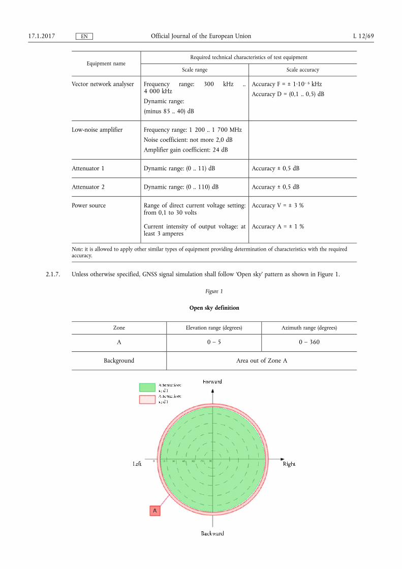
Simulated parameter Value
Signal strength
mdash GNSS Galileo minus 135 dBm
mdash GNSS GPS minus 1385 dBm
Number of simulated satellites mdash at least 6 Galileo satellites
mdash at least 6 GPS satellites
mdash at least 2 SBAS satellites
2214 By means of corresponding serial interface set the connection between the eCall and PC Control the possibility of receiving navigation information via NMEA-0183 protocol The value of field 6 in the GGA messages is set to lsquo2rsquo
2215 Test results are considered successful if navigation information via NMEA-0183 protocol is received in all the eCall samples
2216 The test of NMEA-0183 messages output and the assessment of the positioning accuracy in autonomous static mode can be combined
222 Assessment of positioning accuracy in autonomous static mode
2221 Make connections according to Figure 2
2222 Prepare and turn on the eCall By means of developer software make sure that the GNSS receiver is set up for receiving Galileo GPS and SBAS combined signals Set up the GNSS receiver to output messages according to the NMEA-0183 protocol (GGA RMC VTG GSA and GSV messages)
2223 Set up the simulator in accordance with its operational manual Start simulation of combined Galileo GPS and SBAS signals script with the set parameters given in Table 2
2224 Set up the recording of NMEA-0183 messages after receiving the navigation solution Up to the moment the simulation script is complete the NMEA-0183 messages are output by the GNSS receiver to a file
2225 Upon receiving the navigation solution set up recording of NMEA-0183 messages output by the GNSS receiver to a file up to the moment the simulation script is complete
2226 Extract coordinates latitude (B) and longitude (L) contained in GGA (RMC) messages
2227 Calculate the systematic inaccuracy of coordinates determination on stationary intervals according to formulas (1) (2) for example for latitude coordinate (B)
(1) ΔB(j) = B(j) ndash Btruej
(2) dB frac141N
XN
j frac14 1
ΔBethjTHORN
mdash Btruej is the actual value of B coordinate in j time moment in arc-seconds
mdash B(j) is the determined value of B coordinate in j time moment by the GNSS receiver in arc-seconds
mdash N is the amount of GGA (RMC) messages received during the test of GNSS receiver
2228 Similarly calculate the systematic inaccuracy of L (longitude) coordinate
1712017 L 1271 Official Journal of the European Union EN
2229 Calculate standard deviation (SD) value according to formula (3) for B coordinate
(3) σB frac14
ffiffiffiffiffiffiffiffiffiffiffiffiffiffiffiffiffiffiffiffiffiffiffiffiffiffiffiffiffiffiffiPN
j frac14 1ethΔBethjTHORN minus dBTHORN
2
N minus 1
vuuut
22210 Similarly calculate the SD value for L (longitude) coordinate
22211 Convert calculated coordinates and SD values of latitude and longitude determination from arc-seconds to meters according to formulas (4) ndash (5)
22212 For latitude
(4-1) dBethмTHORN frac14 2 a eth1 minus e2THORN
eth1 minus e2sin2φTHORN3=2 05Prime π
180 3 600Prime dB
(4-2) σBethмTHORN frac14 2 a eth1 minus e2THORN
eth1 minus e2sin2φTHORN3=2 05Prime π
180 3 600Prime σB
22213 For longitude
(5-1) dLethмTHORN frac14 2 a cosφffiffiffiffiffiffiffiffiffiffiffiffiffiffiffiffiffiffiffiffiffi1 minus e2sin2φ
p 05Prime π180 3 600Prime
dL
(5-2) σLethмTHORN frac14 2 a cosφffiffiffiffiffiffiffiffiffiffiffiffiffiffiffiffiffiffiffiffiffi1 minus e2sin2φ
p 05Prime π180 3 600Prime
σL
mdash а mdash Semi-major axis of ellipsoid metres
mdash e mdash first eccentricity [0 ndash 1]
mdash φ mdash determined value of latitude radians
22214 Calculate horizontal position error according to formula (6)
(6) Π frac14ffiffiffiffiffiffiffiffiffiffiffiffiffiffiffiffiffiffiffiffiffiffiffiffiffiffiffiffiffiffiffiffiffiffiffidB2ethmTHORN thorn dL2ethmTHORN
pthorn 2
ffiffiffiffiffiffiffiffiffiffiffiffiffiffiffiffiffiffiffiffiffiffiffiffiffiffiffiffiffi
σ2BethmTHORN thorn σ2
LethmTHORN
q
22215 Repeat test procedures according to 2223 ndash 22214 for GNSS Galileo signals with simulation parameters given in Table 2
22216 Repeat test procedures according to 2223 ndash 22214 only for GPS GNSS signals with simulation parameters given in Table 2
22217 Repeat test procedures according to 2223 ndash 22216 with other eCall samples provided for the test
22218 Determine average values according to (6) obtained for all tested eCall samples
22219 Tests results are considered satisfactory if horizontal position errors as defined by formula (6) obtained with all eCall samples do not exceed 15 metres under open sky conditions at confidence level 095 probability for all simulation scripts
223 Assessment of positioning accuracy in autonomous dynamic mode
2231 Repeat test procedures described in section 222 but 22215 ndash 22216 with simulation script for manoeuvring movement given in Table 3
1712017 L 1272 Official Journal of the European Union EN
Table 3
Main parameters of simulation script for manoeuvring movement
Simulated parameter Value
Test duration hhmmss 010000
Output frequency 1 hertz
eCall location Any specified land point between latitude range 80degN and 80degS in coordishynate system WGS-84
Model of movement Manoeuvring movement
mdash speed kmh 140
mdash turning radius metres 500
mdash turning acceleration metres second2
02
Troposphere Standard predefined model by the GNSS simulator
Ionosphere Standard predefined model by the GNSS simulator
PDOP value in the test time interval
20 le PDOP le 25
Simulated signals Combined GalileoGPSSBAS
Signal strength
mdash GNSS Galileo minus 135 dBm
mdash GNSS GPS minus 1385 dBm
Number of simulated satellites mdash at least 6 Galileo satellites
mdash at least 6 GPS satellites
mdash at least 2 SBAS satellites
2232 Determine average values according to (6) obtained for all tested eCall samples
2233 Tests results are considered satisfactory if horizontal position errors obtained with all eCall samples do not exceed 15 metres under open sky conditions at confidence level 095 probability
1712017 L 1273 Official Journal of the European Union EN
224 Movement in shadow areas areas of intermittent reception of navigation signals and urban canyons
2241 Repeat test procedures described in section 223 for simulation script for movement in shadow areas and areas of intermittent reception of navigation signals (given in Table 4) with an urban canyon signal pattern described in Figure 3
Table 4
Main parameters of movement in shadow areas and areas of intermittent reception of navigation signals
Simulated parameter Value
Test duration hhmmss 010000
Output frequency 1 hertz
eCall location Any specified land point between latitude range 80degN and 80degS in coordishynate system WGS-84
Model of movement Manoeuvring movement
mdash speed kmh 140
mdash turning radius metres 500
mdash turning acceleration metres second2
02
Satellite visibility
mdash signal visibility intervals seconds
300
mdash signal absence intervals secshyonds
600
Troposphere Standard predefined model by the GNSS simulator
Ionosphere Standard predefined model by the GNSS simulator
PDOP value in the test time inshyterval
35 le PDOP le 40
Simulated signals Combined GalileoGPSSBAS
Signal strength
mdash GNSS Galileo minus 135 dBm
mdash GNSS GPS minus 1385 dBm
Number of simulated satellites mdash at least 6 Galileo satellites
mdash at least 6 GPS satellites
mdash at least 2 SBAS satellites
1712017 L 1274 Official Journal of the European Union EN
Figure 3
Urban canyon definition
Zone Elevation range (degrees) Azimuth range (degrees)
A 0 ndash 5 0 ndash 360
B 5 ndash 30 210 ndash 330
C 5 ndash 30 30 ndash 150
Background Area out of Zone A B C
2242 Urban canyon plot- Attenuation
0 dB
B ndash 40 dB
C ndash 40 dB
A ndash 100 dB or signal is switched off
2243 Tests results are considered satisfactory if horizontal position errors obtained with all eCall samples do not exceed 40 metres in urban canyon conditions at confidence level 095 probability
225 Cold start time to first fix test
2251 Prepare and turn on the eCall By means of developer software make sure that GNSS module is set to receive Galileo and GPS signals
2252 Delete all position velocity time almanac and ephemeris data from the GNSS receiver
1712017 L 1275 Official Journal of the European Union EN
2253 Set up the simulator according to the simulator user guide Initialize simulator script with the parameters given in Table 2 for Galileo and GPS signals with signal level minus 130 dBm
2254 By means of a stopwatch measure time interval between signal simulation start and the first navigation solution result
2255 Conduct test procedures according to 2252 ndash 2254 at least 10 times
2256 Calculate average time to first fix in cold start mode based on measurements for all eCall samples provided for the test
2257 The test result is considered to be positive if average values of time to first fix calculated as described in 2256 do not exceed 60 seconds for signal level down to minus 130 dBm for all the simulated signals
2258 Repeat test procedure according to 2251 ndash 2255 with signal level minus 140 dBm
2259 The test result according to 2258 is considered to be positive if average values of time to first fix calculated as described in 2256 do not exceed 300 seconds for signal level down to minus 140 dBm for all the simulated signals
226 Test of re-acquisition time of tracking signals after block out of 60 seconds
2261 Prepare and turn on the eCall according to operational manual By means of the developer software make sure that GNSS receiver is set up to receive Galileo and GPS signals
2262 Set up the simulator according to the simulator user guide Initialize simulator script with the parameters given in Table 2 for Galileo and GPS signals with signal level minus 130 dBm
2263 Wait for 15 minutes and make sure the GNSS receiver has calculated eCall position
2264 Disconnect the GNSS antenna cable from the eCall and connect it again after time interval of 60 seconds By means of stopwatch determine time interval between cable connection moment and restoration of satellites tracking and calculation of the navigation solution
2265 Repeat test procedure according to 2264 at least 10 times
2266 Calculate average value of re-acquisition time of satellite tracking signals by the eCall for all performed measurements and all eCall samples provided for the test
2267 The test result is considered to be positive if average values of re-acquisition time after block out of 60 seconds measured as described in 2266 do not exceed 20 seconds
227 Test of GNSS receiver sensitivity in cold start mode tracking mode and re-acquisition scenario
2271 Turn on the vector network analyser Calibrate the vector network analyser according to its operational manual
1712017 L 1276 Official Journal of the European Union EN
2272 Set up the diagram according to Figure 4
Figure 4
Diagram of path calibration
2273 Set zero signal path attenuation on attenuators Measure the frequency response for a given signal path in the E1L1 band of GalileoGPS respectively Record the average path transmission factor in [dB] in this frequency band
2274 Assemble the circuit shown in Figure 5
Figure 5
Arrangement for evaluation of GNSS module sensitivity
2275 Prepare and turn on eCall according to operational manual By means of developer software make sure that GNSS receiver is set to receive Galileo and GPS signals Clear the GNSS receiver RAM such that the lsquocoldrsquo start mode of the GNSS receiver of the eCall is achieved Check that the position velocity and time information is reset
2276 Prepare GNSS signals simulator according to its operation manual Start Galileo and GPS signals simulation script with parameters given in Table 2 Set output power level of the simulator to minus 144 dBm
2277 By means of a stopwatch measure time interval between signal simulation start and the first navigation solution result
2278 Set the signal path attenuation on attenuators such that the signal on eCall antenna input is equal to minus 155 dBm
2279 By means of a stopwatch verify that the eCall still provides navigation solution for at least 600 seconds
22710 Set the signal path attenuation on attenuators such that the signal on eCall antenna input is equal to minus 150 dBm
22711 Disconnect the GNSS antenna cable from the eCall and connect it again after time interval of 20 seconds
22712 By means of stopwatch determine time interval between cable connection moment and restoration of satellites tracking and calculation of the navigation solution
1712017 L 1277 Official Journal of the European Union EN
22713 The test result is considered to be positive in case
mdash the value of time to first fix in lsquocoldrsquo start mode as measured in 2277 do not exceed 3 600 seconds at signal level on the antenna input of the eCall of minus 144 dBm in all the eCall samples
mdash the GNSS navigation solution is available for at least 600 seconds at signal level on the antenna input of the eCall of minus 155 dBm as measured in 2279 in all the eCall samples
mdash and re-acquisition of GNSS signals and calculation of the navigation solution at signal level on the antenna input of the eCall of minus 150 dBm is possible and time interval measured in 22712 does not exceed 60 seconds in all the eCall samples
1712017 L 1278 Official Journal of the European Union EN
ANNEX VII
In-vehicle system self-test
1 Requirements
11 The following requirements apply to vehicles with eCall in-vehicle system installed STUs and (optionally for) components
12 Performance requirements
121 The eCall system shall carry out a self-test at each system power-up
122 The self-test function shall monitor at least the technical items listed in the Table
123 A warning in form of either a visual tell-tale or a warning message in a common space shall be provided in case a failure is detected by the self-test function
1231 It shall remain activated while the failure is present
1232 It may be cancelled temporarily but shall be repeated whenever the ignition or vehicle master control switch is being activated
13 Documentation requirements
131 The manufacturer shall provide the type-approval authorities with documentation in accordance with the Table which shall contain for each item the technical principle applied to monitor the item
Table
Template of information for self-test function
Item Technical principle applied for monitoring
eCall ECU is in working order (eg no internal hardshyware failure processormemory is ready logic funcshytion in expected default state)
External mobile network antenna is connected
Mobile network communication device is in working order (no internal hardware failure responsive)
External GNSS antenna is connected
GNSS receiver is in working order (no internal hardshyware failure output within expected range)
Crash control unit is connected
No communication failures (bus connection failures) of relevant components in this table
SIM is present (this item only applies if a removable SIM is used)
Power source is connected
Power source has sufficient charge (threshold at the discretion of the manufacturer)
1712017 L 1279 Official Journal of the European Union EN
2 Test procedure
21 Self-test function verification test
211 The following test shall be performed on the vehicle with an eCall in-vehicle system installed in accordance with Article 4 on the STU in accordance with Article 6 or (optionally for) the component that is made part of a complete system for the purpose of the test in accordance with Article 5
212 Simulate a malfunction of the eCall system by introducing a critical failure in one or more of the items monitored by the self-test function according to the technical documentation provided by the manufacturer The item(s) shall be selected at the discretion of the type-approval authority
213 Power the eCall system up (eg by switching the ignition lsquoonrsquo or activating the vehicles master control switch as applicable) and verify that the malfunction indicator illuminates shortly afterwards
214 Power the eCall system down (eg by switching the ignition lsquooffrsquo or deactivating the vehicles master control switch as applicable) and restore it to normal operation
215 Power the eCall system up and verify that the malfunction indicator does not illuminate or extinguishes shortly after illuminating initially
3 Modification of type of 112-based eCall in-vehicle system or STU
31 When the manufacturer submits an application for revision or extension of an existing type-approval for the purpose of including an alternative GNSS antenna electronic control unit mobile network antenna andor power source components no retesting of 112-based eCall in-vehicle system components shall be required for the purpose of fulfilling the requirements of this Annex provided that those type-approved components possess at least the same functional features and that they are indeed covered by this Annex in accordance with Article 5(3)
1712017 L 1280 Official Journal of the European Union EN
ANNEX VIII
Technical requirements and test procedures related to privacy and data protection
PART I
Procedure for verifying the lack of traceability of an eCall in-vehicle system or STU
1 Purpose
11 This test procedure is to ensure that a 112-based eCall in-vehicle system or STU is not traceable and is not subject to any constant tracking in its normal operational status
2 Requirements
21 The 112-based eCall in-vehicle system or STU is not available for communication with the PSAP if the PSAP test point initiates the communication
22 Failure to establish the connection can be attributed to the 112-based eCall in-vehicle system not being registered on the network
3 Test procedure
31 The following tests shall be performed on a representative arrangement of parts (without a vehicle body)
32 This test shall be performed after successful connection of the eCall IVS with the network and registration of the device so as to facilitate transmission of the MSD
321 The initial emergency call must have been lsquocleared downrsquo and deregistered from the network prior to this test (eg hang up) otherwise the PSAP test point will be enabled to connect
322 Before performing the test ensure that
(a) one of the connection procedures defined in point 27 of Annex I to this Regulation as agreed between the technical service and the manufacturer will be applied for any test call
(b) the dedicated PSAP test point is available to receive an eCall emitted by the 112-based system
(c) the vehicle ignition or master control switch is activated
(d) any TPS or added-value service system is disabled
323 Leave the 112-based eCall IVS powered
324 Via the PSAP test point attempt to connect to the 112-based eCall IVS
4 Assessment
41 The requirement is determined to have been passed if the 112-based eCall in-vehicle system is not available for communication with the PSAP when the PSAP test point attempts to connect
42 The establishment of connection with the 112-based eCall IVS when the PSAP test point initiates the communishycation constitutes a failure
PART II
Procedure for verifying the length of time an eCall log file is stored by the eCall in-vehicle system or STU
1 Purpose
11 This test procedure aims to ensure that personal data processed pursuant to Regulation (EU) 2015758 is not retained by the eCall in-vehicle system longer than necessary for the purpose of handling the emergency situation and is fully deleted as soon as no longer necessary for that purpose
1712017 L 1281 Official Journal of the European Union EN
12 This is to demonstrate the automatic deletion by proving that eCall log files are not kept beyond 13 hours from the point of initiating an eCall
2 Requirements
21 When interrogated the eCall in-vehicle system or STU shall not maintain any record of an eCall in its memory beyond 13 hours from the point of initiating an eCall
3 Test conditions
31 The Technical Service shall be facilitated to have access to the part of the system where the eCall log files are stored in the IVS
32 The following test shall be performed on a representative arrangement of parts
4 Test Method
41 The tests as described in point 27 of Annex I shall be carried out They require that a test call is placed in order for functionality checks to be made
42 13 hours after a test call has been placed the Technical Service tester shall be facilitated with access to where the eCall log files are stored in the IVS This will involve the potential to download from the IVS any log files so that they can be viewed by the tester
5 Assessment
51 The requirement is determined to have been passed if no log files are present in the eCall in-vehicle system memory
52 The presence of a log file pertaining to an eCall that has occurred more than 13 hours ago constitutes a failure
PART III
Procedure for verifying the automatic and continuous removal of data in the internal memory of an eCall in-vehicle system or STU
1 Purpose
11 This test procedure aims to ensure that personal data is only used for the purpose of handling the emergency situation and is automatically and continuously removed from the internal memory of the eCall in-vehicle system or STU
12 This is to be proved by demonstrating that in the internal memory of the 112 based eCall in-vehicle system or STU maximum of last three locations of the vehicle are retained
2 Requirements
21 When interrogated the eCall in-vehicle system or STU shall not maintain more than three recent locations of the vehicle
3 Test conditions
31 The Technical Service shall be facilitated to have access to the part of the system where the vehicle location data are stored in the IVS internal memory
1712017 L 1282 Official Journal of the European Union EN
32 The following test shall be performed on a representative arrangement of parts
4 Test Method
41 The Technical Service tester shall be facilitated with access to where the vehicle location data are stored in the IVS internal memory This will involve the potential to download from the IVS any stored locations so that they can be viewed by the tester
5 Assessment
51 The requirement is determined to have been passed if maximum of last three locations are present in the eCall in-vehicle system memory
52 The presence of more than three locations constitutes a failure
PART IV
Procedure for verifying the non- exchange of personal data between an eCall in-vehicle system or STU and third party services systems
1 Purpose
11 This test procedure shall ensure that the 112-based eCall in-vehicle system or STU and any additional system functionality providing TPS eCall or an added-value service are designed in such a way that no exchange of personal data between them is possible at any time
2 Requirements
21 The following requirements apply to eCall in-vehicle systems or STUs that shall be used in conjunction with a TPS eCall in-vehicle system functionality
22 Performance requirements
221 There is no exchange of personal data between the 112-based eCall in-vehicle system or STU and any additional system functionality providing TPS eCall or an added-value service
222 Following an eCall made via the 112-based eCall in-vehicle system or STU no log of this eCall shall be recorded in the memory of the TPS eCall or added-value service system
3 Test procedure
31 The following tests shall be performed either on a vehicle with an eCall in-vehicle system installed or on a repshyresentative arrangement of parts
32 The TPS system shall be disabled for the duration of the test call
321 Before performing the test call ensure that
(a) one of the connection procedures defined in point 27 of Annex I to this Regulation as agreed between the technical service and the manufacturer will be applied for any test call
(b) the dedicated PSAP test point is available to receive an eCall emitted by the 112-based system
(c) a false eCall to a genuine PSAP cannot be made over the live network and
(d) the vehicle ignition or master control switch is activated
322 Perform a test call by applying a manual trigger of the system (push mode) with the TPS disabled
323 Verify that a call was established with the PSAP test point by a record of the PSAP test point showing that it received a call initiation signal or by a successful voice connection to the PSAP test point
1712017 L 1283 Official Journal of the European Union EN
324 Clear down the test call using the appropriate PSAP test point command (eg hang up)
325 If the call attempt of the 112-based system fails during the test the test procedure may be repeated
33 The lack of a log file in the TPS system shall be verified via access to the part of the system where eCall log files are stored
331 The Technical Service tester shall be facilitated with access to where the eCall log files are stored in the IVS This will involve the potential to download from the IVS any log files so that they can be viewed by the tester
332 The requirement is determined to have been passed if no log files are present in the TPS system in-vehicle system memory
333 The presence of a log file in the TPS system pertaining to an eCall that has occurred via the 112-based system constitutes a failure
34 Connection procedures
The connection procedures defined in point 27 of Annex I to this Regulation shall apply
1712017 L 1284 Official Journal of the European Union EN
ANNEX IX
Classes of vehicles referred to in Article 2
Armoured vehicles of categories M1 and N1 as defined in point 52 of Part A of Annex II to Directive 200746EC equipped with armoured security glazing class BR 7 according to the classification under European standard EN 10632000 (Test and Classification for Ballistic Security Glazing) and with body parts complying with European standard EN 15221999 (Bullet Resistance in Windows Doors Shutters and Blinds) where those vehicles due to their special purpose cannot meet the requirements of Regulation (EU) 2015758 and of this Regulation
1712017 L 1285 Official Journal of the European Union EN
- COMMISSION DELEGATED REGULATION (EU) 201779 of 12 September 2016 establishing detailed technical requirements and test procedures for the EC type-approval of motor vehicles with respect to their 112-based eCall in-vehicles systems of 112-based eCall in-vehicle separate technical units and components and supplementing and amending Regulation (EU) 2015758 of the European Parliament and of the Council with regard to the exemptions and applicable standards (Text with EEA relevance)
-
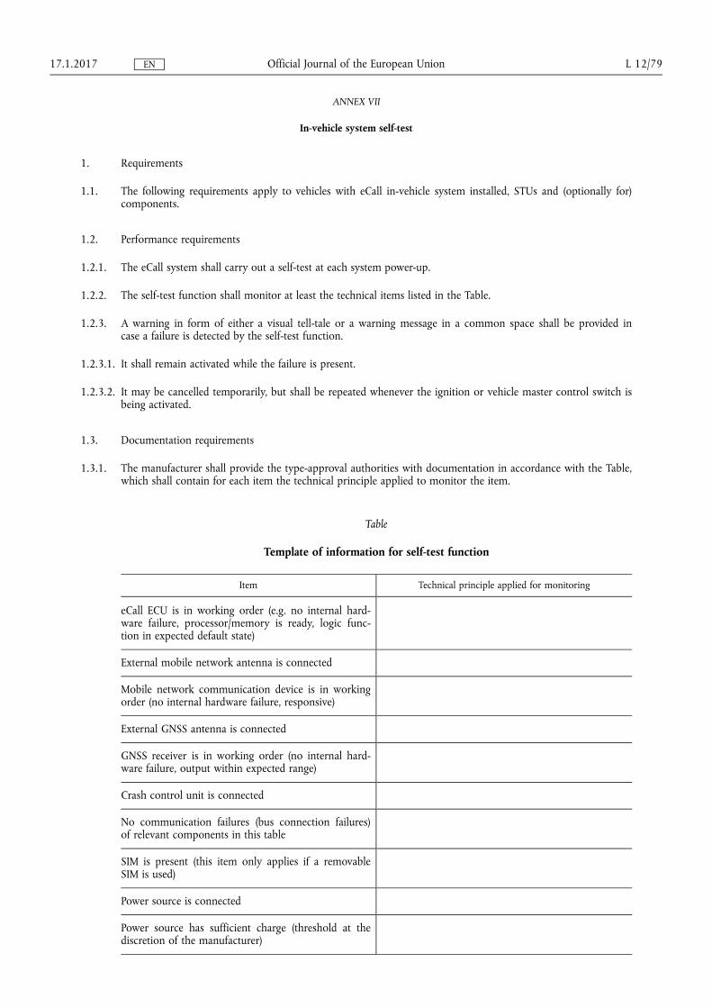