l0709063
TRANSCRIPT

SE/ NRS
CRAFTSMODEL NUMBER 917.258572 OWNER'S MANUAL
®
o AssemblyOperationCustomer ResponsibilitiesService and AdjustmentsRepair Parts
CAUTION: Read and follow all safety rules and instructions before operating this equipment.FOR CONSUMER ASSISTANCE HOT LINE, CALL THIS TOLL FREE NUMBER: 1-800-659-5917
E__
1

SAFETY RULESSafe Operation Practices for Ride=On Mowers
IMPORTANT: THIS CUTTING MACHINE IS CAPABLE OF AMPUTATING HANDS AND FEET AND THROWING OBJECTS.FAILURE TO OBSERVE THE FOLLOWING SAFETY INSTRUCTIONS COULD RESULT IN SERIOUS INJURY OR DEATH.
L GENERAL OPERATION
,, Read, understand, and follow all instructions in the manualand on the machine before starting.
,, Only allow responsible adults, who are familiar with theinstructions, to operate the machine.
,, Clear the area of objects such as rocks, toys, wire, etc.,which could be picked up and thrown by the blade.
• Be surethe area is clear of other people before mowing. Stopmachine if anyone enters the area.
,, Never carry passengers.,, Do not mow in reverse unless absolutely necessary. Always
look down and behind before and while backing.
,, Be aware of the mower discharge direction and do not pointit at anyone. Do not operate the mower without either theentire grass catcher or the guard in place.
,, Slow down before turning.,, Never leave a running machine unattended. Always turn off
b]ades, set parking brake, stop engine, and remove keysbefore dismounting.
• Turn off blades when not mowing.
• Stop engine before removing grass catcher or uncloggingchute.
• Mow on_y in daylight or good artificial light.,, Do not operate the machine while under the influence of
alcohol or drugs.• Watch for traffic when operating near or crossing roadways.• Use extra care when loading or unloading the machine into
a trailer or truck.
II. SLOPE OPERATION
Slopes are a major factor related to less-of-control andtipover accidents, which can result in severe injury ordeath. All slopes require extra caution. If you cannot backup the slope or if you feel uneasy on it, do not mow it.
DO:
• Mow up and down slopes, not across.. Remove obstacles such as rocks, tree limbs, etc.• Watch for ho[es, ruts, or bumps. Uneven terrain could
overturn the machine. Tal! grass can hide obstacles.• Use slow speed. Choose a low gear so that you will not have
to stop or shift while on the slope.• Follow the manufacturer's recommendations for wheel
weights or counterweights to improve stab{lity.• Use extra care with grass catchers or other attachments.
These can change the stability of the machine.. Keep all movement on the slopes slew and gradual Do not
make sudden changes in speed or direction.• Avoid starting or stopping on a slope. If tires lose traction,
disengage the blades and proceed slowly straight down theslope.
DO NOT:
* Donot turn on slopes unless necessary, and then, turn slowlyand gradually downhill, if possible.
* Do not mow near drop-offs, ditches, or embankments. Themower could suddenly turn over if a wheel is over the edgeof a cliff or ditch, or if an edge caves in.
, Do net mow on wet grass. Reduced traction could causesliding.
* Do not try tOstabilize the machine by putting your foot on theground.
, Do net use grass catcher on steep stopes.
Ill. CHILDREN
Tragic accidents can occur if the operator is not alert to thepresence of children. Children are often attracted to themachine and the mowing activity. Never assume thatchildren will remain where you last saw them.
• Keep children out of the mowing area and under the watchfulcare of another responsible adult.
• Be alert and turn machine off if children enter the area.
,, Before and when backing, look behind and down for smallchildren.
, Never carry children. They may fail off and be seriouslyinjured or interfere with safe machine operation.
• Never allow children to operate the machine.• Use extra care when approaching blind corners, shrubs,
trees, or other objects that may obscure vision.
IV. SERVICE
• Useextra care in handling gasoline and other rue s. They areflammable and vapors are explosive.
Use only an approved container.Never remove gas cap or add fuel with the enginerunning. Allow engine to coo! before refueling. Do notsmoke.Never refuel the machine indoors.Never store the machine or fue! container inside wherethere is an open flame, such as a water heater.
• Never run a machine inside a closed area.
, Keep nuts and bolts, especially blade attachment bolts, tightand keep equipment in good condition.
• Never tamper with safety devices. Check their properoperation regularly.
• Keep machine free of grass, Ieaves, or other debris build-up.Clean oil or fuel spillage. Allow machine to cool beforestoring.
• Stop and inspect the equipment if you strike an object.Repair, if necessary, before restarting.
• Never make adjustments or repairs with the engine running.• Grass catcher components are subject to wear, damage, and
deterioration, which could expose moving parts or allowobjects to be thrown. Frequently check components andreplace with manufacturer's recommended parts, when nec-essary.
• Mower blades are sharp and can cut. Wrap the blade(s) orwear gloves, and use extra caution when servicing them.
• Check brake operation frequently. Adjust and service asrequired.
='-"_ Lookfor this symbol to point out importantsafety precautions. . It meansCAUT!ONf!! BECOME ALERT!f! YOUR
ACAUTION: Always disconnect spark plugwire and place wire where it cannot contactspark plug in order to prevent accidentalstarting when setting up, transporting,adjusting or making repairs.
A WARNING AThe engine exhaust from this product containschemicals known to the State of California tocause cancer, birth defects, or other reproduc-tive harm.

CONGRATULATgONS on your purchase of a SearsTractor. It has been designed, engineered and manufac-tured to give you the best possible dependability andperformance.Should you experience any problem you cannot easilyremedy, please contact your nearest Sears AuthorizedService Center!Department Department. We have com-petent, well-trained technicians and the proper tools toservice or repair this tractor.Please read and retain this manual. The instructions willenable you to assemble and maintain your tractor properly.Always observe the "SAFETY RULES".
MODEL
NUMBER 917.258572
SERIALNUMBER
DATEOF PURCHASE
THE MODELAND SERIAL NUMBERS WILL BE FOUND
ON A PLATE UNDER THE SEAT.
YOU SHOULD RECORD BOTH SERIAL NUMBER AND
DATE OF PURCHASE AND KEEP IN A SAFE PLACE
FOR FUTURE REFERENCE.
MABNTENANCE AGREEMENTA Sears Maintenance Agreement is available on this prod-uct. Contact your nearest Sears store for details.
PRODUCT SPECIF|CATIONS
HORSEPOWER: 19.0
GASOLINE CAPACITY 3.5 GALLONSAND TYPE: UNLEADED REGULAR
OIL TYPE (API-SF/SG/SH): SAE 30 (above 32°F)SAE 5W-30 (below 32°F)
-_ CAPACITY: 3.0 PINTS
SPARK PLUG: CHAMPION RJtgLM(GAP: ,030")
VALVE CLEARANCE: INTAKE: .004"- .006"EXHAUST: ,007" - .009"
GROUND SPEED (MPH): FORWARD: 0 - 5.5REVERSE: 0-2.4
TIRE PRESSURE: FRONT: 14 PSIREAR: 10 PSI
CHARGING SYSTEM: 3 AMPS BATTERY5 AMPS HEADLIGHTS
BATTERY: AMPiHR: 30
MIN. CCA: 240CASE SIZE: U1R
BLADE BOLT TORQUE: 30-35 FT. LBS.
CUSTO[VlER RESPONSaBILITmESRead and observe the safety rules.
• Fol!owaregularscheduleinmaihtaining, caringforandusing your tractor.Follow the instructions under"Customer ResponsibilFties" and "Storage" sections of this owner's manual.
WARNING: This tractor is equipped with an internalcombustion engine and should not be used on or near anyunimproved forest-covered, brush-covered or grass-cov-
ered land unless the engine's exhaust system is equippedwith a spark arrester meeting applicable loca! or state laws(if any). If a spark arrester is used, it should be maintainedin effective working order by the operator.In the state of California the above is required by law(Section 4442 of the California Public Resources Code).Other states may have similar laws. Federaf laws apply onfederal iands. A spark arrester for the muffler is availablethrough your nearest Sears Authorized Service Center/Department (See REPAIR PARTS section of this manual).
LI ' TED TWO YEAR WARRANTY ON CRAFTSMAN R#D NG EQUIPMENTFor two (2) years from the date of purchase, if this Craftsman Riding Equipment is maintained, lubricated and tuned up accordingto the instructions in the owner's manual, Sears will repair or replace, free of charge, any parts found to be defective in material orworkmanship.This Warranty does not cover:.• Expendable items which become worn during normal use, such as blades, spark plugs, air cleaners, belts, etc.
Tire replacement or repair caused by punctures from outside objects, such as nails, thorns, stumps, or giass., Repairs necessary because of operator abuse, negligence, improper storage or accident or the failure to maintain the
equipment according to the instructions contained in the owner's manual.Riding equipment used for commercial or rental purposes.
LIMITED 90 DAY WARRANTY ON BATTERYFor ninety (90) days from date of purchase, if any battery included with this riding equipment proves defective in material orworkmanship and our testir_g determines the battery will not hold a charge, Sears will replace the battery at no charge.
IN-HOME WARRANTY SERVICE ON YOUR CRAFTSMAN RIDING EQUIPMENT IS AVAILABLE AT NO-CHARGE FOR 30DAYS FROM THE DATE OF PURCHASE. PLEASE CONTACT YOUR NEAREST SERVICE CENTER. AFTER 30 DAYS FROMTHE DATE OF PURCHASE, WARRANTY SERVICE IS AVAILABLE BY TAKING YOUR CRAFTSMAN RIDING EQUIPMENT TOYOUR NEAREST SEARS SERVICE CENTER. (IN-HOME WARRANTY SERVICE WILL STILL BE AVAILABLE AFTER 30 DAYSFROM THE DATE OF PURCHASE BUT A STANDARD TRIP CHARGE WILL APPLY.) THIS WARRANTY APPLIES ONLYWHILE THIS PRODUCT IS IN THE UNITED STATES.
This Warranty gives you specific legal rights, and you may a[so have other rights which may vary from state to state.
SEARS, ROEBUCK AND CO., D/8!7 WA, HOFFMAN ESTATES, IL 60179

TABLE OF CONTENTS
SAFETY RULES ............................................................ 2PRODUCT SPECIFICATIONS ...................................... 3CUSTOMER RESPONSIBILITIES ..................... 3, 17-19WARRANTY .................................................................. 3TABLE OF CONTENTS .............................. :_........ :........ 4INDEX ............................................................................ 4TRACTOR ACCESSORIES .......................................... 5ASSEMBLY ................................................................ 7-9
OPERATION ........................................................... 11-14MAINTENANCE SCHEDULE ...................................... 16SERVICE AND ADJUSTMENTS ............................ 20-26STORAGE ................................................................... 2?'TROUBLESHOOTING ............................................ 28-29REPAIR PARTS - TRACTOR ................................. 31-48REPAIR PARTS - ENGINE .................................... 49-55PARTS ORDERING/SERVICE .................. BACK PAGE
NDEXA
Accessories ........................ :................... 5
Adjustments:Brake ........................................... 22Carburetor ................................... 25Mower:
Front-To-Back ........................ 21Side-To-Side .......................... 21
Throttle Control Cable ................. 25
Air Filter, Engine ........... _..................... 18Air Screen, Engine ............................. 18Assembly ............................................ 7-9
8
Battery:Charging ..................................... 17Cleaning ...................................... 17Starting with Weak Battery ......... 24Storage ....................................... 27Terminals .................................... 17
Betts:Motion Drive
Removal/Replacement .......... 22Mower Blade Ddve
Removal/Replacement .......... 22Blade:
Sharpening ................................. 17Replacement ............................... 17
Brake Adjustment ............................... 22C
Carburetor Adjustment ....................... 25Controts, Tractor ................................ 12
Customer Responsibilities ......... 3,17-19Engine:
Air Filter ................................... 18
Air Screen, Engine .................. 18Battery ..................................... 17Cooling Fins, Engine ............... 19Engine Oil ............................... 18Fuel Filter ................................ 19
Spark Plugs ............................ 19Tractor:
Blades ..................................... 17Lubrication Chaff .................... 16Maintenance Schedule ........... 16
Tire Care ......................... 8,17,23
Cutting Height, Mower ....................... 12
EElectrical:
interlocks and Relays ................. 24Schematic ................................... 30Wiring Diagram ........................... 31
Engine:Air Filter ....................................... 18Air Screen ................................... 18
Cooling Fins, Engine ................... 19Oil Change .................................. 18Oil Lever ................................. 13,18Oil Type ....................................... 18Preparation ................................. 13
Repair Parts ........................... 49-55Starting ........................................ 13Storage ....................................... 27
FFilters:
Air ................................................ 18Fuel ............ . ................................ 1g
Fuel: _.Type ............................................ 13
' Storage ....................................... 27Fuse ................................................... 24
G
Gauge Wheels ..................................... 8H
Hood Removal!InstaJJation ................. 24L
Leveling Mower Deck ......................... 21Lubrication Chart ................................ 16
M
Maintenance Schedule ...................... 16Mower:
Adjustment, Front-to-Back .......... 21Adjustment, Side-to-Side ............ 21
Blade Sharpening ....................... 17Blade Replacement .................... 17Cutting Height ............................. 12Installation ................................... 20
Operation ............................... 11-14Removal ...................................... 20
Mowing Tips ....................................... 14Muffler ................................................ 19
Spark Arrester .......................... 3,41Mulcher Plate ....................................... 9
OOil:
Cold Weather Conditions ....... t3,18Engine ......................................... 18Storage ....................................... 27
Operation ...................................... 11-14Operating Mower .......................... 12-13Options:
Accessories ................................... 5
Spark Arrester .......................... 3,41P
Parking Brake ............................... 11-12Parts Bag ............................................. 6Parts, Replacement!Repair ........... 31-48
Product Specifications ........................... 3R
Repair Parts .................................. 31-48S
Safety Rules ......................................... 2Seat ...................................................... 8
Service and Adjustments .............. 20-26Brake ........................................... 22Carburetor ................................... 25Fuse ............................................ 24Hood Removaltlnstallation .......... 24Motion Drive Belt
Removal/Replacement .......... 22Mower Blade Drive Belt
Removal!Replacement .......... 22Mower Ad)ustment:
Front-to-Back ......................... 21Side-to-Side ........................... 2_
Mower Installation ....................... 20Mower Removal .......................... 20
Tire Care ............................. 8,17,23Slope Guide Sheet ............................. 56Spark Plugs ........................................ lgSpecifications ....................................... 3
Starting the Engine ....................... 13-14Steering Wheel ............................... 7,23
Stopping the Tractor .......................... 12Storage ............................................... 27
T
Throttle Control Cable Adjustment ..... 25Tires ........................................... 8,17,23
Trouble Shooting Chart .................. 28-29
Transaxle Repair Parts ................. 47-48W
Warranty ............................................... 3
Widng Diagram .................................. 31Wiring Schematic ............................... 30
4

J=
ACCESSORI ATTACHThese accessories and attachments were available through most Sears retail outlets and service centers when the tractor was purchased.Most Sears stores can order these items for you when you provide the model number of your tractor.
ENGINE
SPARK PLUG GAS CAN ENGINE OIL FUEL STABILIZER
MAINTENANCE
AIR FILTER E_LADES BELTS
PERFORMANCE
Sears offers a wide variety of attachments that fit your tractor. Many of these are listed below with brief explanations of how they can helpyou. This list was current atthe time of publication; however, it may change in future years - more attachments may be added, changesmay be made in these attachments, or some may no longer be available or fit your model. Contact your nearest Sears store for theaccessories and attachments that are available for you_" tractor.
Most of these attachments do not require additional hitches or conversion kits (those lhat do are indicated) and are designed for easyattaching and detaching.
AERATOR promotes deep root growth for a healthy lawn. Ta-pered 2.5-inch steel spikes mounted on 10-inch diameter discspuncture holes in soil at close intervals to tel moisture soak in.Steel weight tray for increased penetration.
BAGGER tets you collect grass clippings and leaves for ahealthier, neater looking lawn. Two Permanex containers hold30-gallon plastic bags.
BUMPER protects fiont end of tractor from damage.
CARTS make hauling easy. Variety of sizes available, plusaccessories such as side panel kits, tool caddy, cad cover,protective mat and dolly.
CORING AERATOR takes small plugs out of soil to allow mois-ture and nutrients to reach grass roots. 36-inch swath. 24hardened steel coring tips. !50 lb. capacity weight tray.
EASY OIL DRAIN VALVE makes oil changes easier, faster.FRONT NOSE ROLLER canters in front of mower deck to reducechances of "scalping" on uneven terrain.
GANG HITCH iets you tow 2 or 3 pull-behind attachments at once,such as sweepers, dethatchers, aerators (not for use with rollers,carts or other heavy attachments).GAUGE WHEELS on both sides of the mower deck reducechances of "scalping" on uneven terrain. For mower decks not soequipped.
MULCH RAKF=JDETHATCHER loosens soil and flips thatch andmatted leaves to lawn sudace for easy pickup. Twenty spring tineteeth. Usefulto prepare bare areas for seeding. Availablefor frontor rear mounting. HiGH PERFORIVlANCE REEL-ACTIONSPRING T_NE DETHATCHER covers 36-inch wide path andtosses thatch into large hopper. Mounts behind tractor.
MULCHING CLOSE-OUT PLATE KiT, once installed, lets youmulch, discharge or bag clippings (bagger optional) withoutchanging blades. For models not equipped as 3-in-1 Convertiblemowers. See "MOWER" in the Repair Parts section of thismanual.
RAMP TOPS AND FEET let you load and unload tractor from apickup truck. Use with 2 x 8 or 2 x 10 lumber.ROLLER for smoother lawn surface. 36-inch wide, 18-inchdiameter water-tight drum holds up to 390 Ibs. of weight. Roundededges prevent harm to turf. Adjustable scraper automaticallycleans drum.
SNOW BLADE forsnow removal on!y. 14-inch high, 48-inch wideblade clears 42-inch path when angled left or fight. Raises, lowerswith side lever. Adjustable skids; replaceable, reversible scraperbar. (Use with tire chains and wheel weights and/or rear drawbarweight.)
SNOWTHROWER has 40-inch swath. Drum-type auger handlespowdery and wet/heavy snow. Mounts easily with simple pinarrangement. Discharge chute adjusts from tractor seat. 6-inchdiameter spout discharges snow 10 to 50 feet. Lift controlled attractor seat. (Use with chains and wheel weights and/or reardrawbar weight.)SPRAYERS use 12-volt DC electric motor that connects to thetractor battery or other 12-volt source. Includes booms forautomatic spraying and hand held wand for spot spraying. Wandhas adjustable spray pattern. For applying herbicides, insecti-cides, fungicides and liquid fertilizers.
SPREADERiSEEDERS make seeding, fertilizing, and weed kill-ing easy. Broadcast spreaders are also useful for granular de-icers and sand.
SWEEPERS let you collect grass clippings and leaves.
T_LLER has 5 hp engine and 36-inch swath to prepare seed beds,cultivate and compost garden residue. Tiller has its own built-inlift and depth contro! system and does NOT require a sleeve hitch.Fits any lawn, yard or garden tractor. Simpiy hook up to the tractordrawbar and go! OptionaJ accessories convert unit fordethatching, aerating, hilling...without tools.
TIRE CHAINS are heavy duty; closeiy spaced extra-large crosslinks give smooth ride, outstanding traction.
TRACTOR CAB has heavy duty vinyl fabric over tubular steelframe, ABS plastic top; clear plastic windshield offers 360 degreevisibility. Hinged metal doors with catch. Keeps operator warmand dry. Remove vinyl sides and windshields for use as sunprotector in summer. Optional accessories include: tinted/tempered solid safety glass windshield with hand operated wiper;12-volt amber caution light for mounting on cab top.
VACS for powerful collection of heavy grass clippings and leaves.Optional wand attachment to pick up debris in hard-to-reachpieces. VAC/CHIPPER includes a chipper-shredder.
WEIGHT BRACKET for drawbar for Snow removal applications.Uses (1) 55 lb, weight.WHEEL WEIGHTS for rear wheels provide needed traction forsnow removal or dozing heavy materials.
5

CONTENTS OF
Parts Bag contents shown full size
(1) Hex Bolt
, 3/8-16 x 1
(1) Large Flat Washer (!) Lockwasher 3/8
[1) HexBolt 5/16-18x 1-1/4 (1)kocknut 5/16-18
(1) Shoulder (1) FJex BoltBolt 5/16-18 1/2-13 x 1
(1) Washer
17/32 x1-3/16.x 12
Gauge (!) LockWasher 1/2
(2) Lock (2) Screws _h_#10 x 5/8
#10O '(5216Washersx3/4 (2) Weld
x 16Gauge Nuts #10
(2) Hex Bolts 1/4-20 x 3/4@
(2) Hex Nuts 1/4-20
(2) Washers 9/32 x 5/8 x 16 Gauge_ I2 Lock Washers 1/4
HARDWARE PACKs
=
Parts packed separately in carton
Seat
VideoCassette
SteeringWheel Mulcher
Plate
SteeringBoot
Manual Pa_s Bag
Parts bag contents not shown ful! size
/F_, (2) Washers 3/8k_.._J x 7/8 x 14 Gauge
(2) ShoulderBolts _--'_ (2) Gauge
f Wheels
Steering WheelAdapter
(2) Center-lock Nuts
Assemblys
- (2) Keys
_ Steering
J WheelInsert
Slope Sheet
I teering
ExtensionShaft

ASSEMBLYYour new tractor has been assembled at the factory with exception of those parts left unassembied for shipping purposes.To ensure safe and proper operation of your tractor all parts and hardware you assemble must be tightened securely. Usethe correct tools as necessary to insure proper tightness,
TOOLS REQUIRED FOR ASSEMBLYA socket wrench set will make assembly easier. Standardwrench sizes are listed.
(1) 3/4" Socket w!drive rachet(2) 7/16" wrenches Phillips Screwdriver(1) 1/2" wrench Tire pressure gauge(1) 9/16" wrench Utility knifeWhen right or teft hand is mentioned in this manual, itmeans when you are in the operating position (seatedbehind the steering wheel).
TO REMOVE TRACTOR FROM CARTON
UNPACK CARTON
- Remove alt accessible loose parts and parts cartonsfrom carton (See page 6).
+ Cut, from top to bottom, along iines on all four cornersof carton, and lay panels flat.
= Check for any additional loose parts or cartons andremove.
BEFORE ROLLING TRACTOR OFF SKID
ATTACH STEERING WHEEL (See Fig. 1)
ASSEMBLE EXTENSION SHAFT AND BOOT
- Slide extension shaft onto lower steering shaft. Alignmounting holes in extension and lower shafts andinstall 5/16 hex bolt and Iocknut. Tighten sScurely.
_MPORTANT: TIGHTEN BOLT AND NUT SECURELY TO18-22 FT. LBS TORQUE.
" Place tabs of steering boot over tab slots in dash andpush down to secure.
INSTALL STEERING WHEEL
+ Position front wheels of the tractor so they are pointingstraight forward.
+ Slide steering wheel adapter onto steering shaft: exten-sion.
+ Position steering wheel so cross bars are horizontal(left to right) and slide inside boot and onto adapter.
• Assemble large flat washer, 3/8 lock washer, 3/8 hexbo!t and tighten securely.
+ Snap steering wheel insert into center of steeringwheel.
, Remove protective materials from tractor hood andgrill.
IMPORTANT: CHECKFORANDREMOVEANYSTAPLESIN SKID THAT MAY PUNCTURE TIRES WHERETRACTORIS TO ROLL OFF SKID.
TO ROLL TRACTOR OFF SKID (See Opera-tion section for location and function of con=trois)
+ Press lift lever ptunger and raise attachment lift lever toits highest position.
• Re!ease parking brake by depressing clutch/brakepedal,
STEERING i ......... }.WHEEL
STEERINGBOOT
FIG. 1
, Place freewheel controi in freewheeling position todisengage transmission (See "TO TRANSPORT" inthe Operation section of this manual).
, Roll tractor backwards off skid.
• Remove banding holding discharge guard up againsttractor.
HOW TO SET UP YOUR TRACTOR
CONNECT BATTERY (See Fig. 2)
A CAUTION: Do not s.hort battery termi-nalsby allowing a wrench or any otherobject to contact both terminals at thesame time. Before connecting battery,remove metal bracelets, wristwatchbands, rings, etc,
Positive terminal must be connectedfirst to prevent sparking from acciden-tal grounding.
° Lift hood to raised position.
+ Open terminal access doors, remove terminal protec-tive caps and discard.
• if this battery is put into service after month and yearindicated on label (label located between terminals)charge battery for minimum of one hour at 6-10 amps.
, First connect RED battery cable to positive (+) batteryterminal with hex bolt, flat washer, lock washer and hexnut as shown. Tighten securely.

o
ASSEMBLY
Use terminal access doors for:
• Inspection for secure connections (to tighten hard-
Connect BLACK grounding cable to negative (-) batteryterminal with remaining hex bolt, flat washer, lockwasher and hex nut. Tighten securely.Close terminal access doo?s.
CHECK TIRE PRESSURE
The tires on your tractor were overinflated at the factory forshipping purposes. Correct tire pressure is important forbest cutting performance.
- Reduce tire pressure to PSI shown in "PRODUCTSPECIFICATIONS" on page 3 of this manual.
ware).
• Inspection for corrosion.
= Testing battery.
, Jumping (if required).
, Periodic charging.
HEX NUT
DISCARD TERMINAL XPROTECTIVE CAPS
LOCKWASHER
FLATWASHER
POSITIVE(RED)CABLE
NEGATtVE(BLACK)CABLE
F_G. 2
CHECK DECK LEVELNESS
For best cutting results, mower housing should be properlyleveled. See 'q'O LEVEL MOWER HOUSING" in theService and Adjustments section of this manual.
CHECK FOR PROPER POSITION OF ALLBELTS
See the figures that are shown for replacing motion andmower blade drive belts in the Service and Adjustmentssection of this manual. Verify that the belts are routedcorrectly.
CHECK BRAKE SYSTEM
After you learn how to operate your tractor, check to seethat the brake is properly adjusted. See "TO ADJUSTBRAKE" in the Service and Adjustments section of thismanual.
ASSEMBLE GAUGE WHEELS. TO MOWERDECK (See F{g. 4)
The gauge wheels are designed to keep the mower deck inproper position when operating mower. Be sure they areproperlY adjusted to ensure optimum mower performance.
INSTALL SEAT (See Fig. 3)Adjust seat before tightening adjustment bolt.• Remove cardboard packing on seat pan.
, Place seat on seat pan and assembte shoulder bolt.- Assemble adjustment bolt, lock washer and flat washer
toosely. Do not tighten.
Tighten shoulder bolt securely.• Lower seat into operating position and sit on seat.
, Slide seat until a comfortable position is reached whichallows you to press clutch/brake pedal all the waydown.
• Get off seat without moving its adjusted position.
, Raise seat and tighten adjustment bolt securely.
SEA__
s.O.LOE=---- \\\
LARO= LATWASBE=
FIG. 3
Assemble gauge wheels with tractor on a flat levelsurface.
* Adjust mower to desired cutting height (See 'q*o AD-JUST MOWER CUTTING HEIGHT" in the Operationsection of this manual).
With mower in desired height of cut position, gaugewheels shouid be assembled so they are slightly off theground. Install gauge wheel in appropriate hole withshoulder bolt, 3/8 washer, and 3/8-16 Iocknut andtighten securely.
Repeat for opposite side installng gauge wheel insame adjustment hole.

LYiNSTALL MULCHER PLATE
(See Figs. 5 & 6)Install two latch hooks to mulcher plate using screw,washer, lock washer, and weld nut as shown.
NOTE: Pre-assemble weld nut to latch hook by insertingweld nut from the top with hook pointing down.• Tighten hardware securely.• Raise and hold deflector shield in upright position.
Place front of mulcher plate over front of mower deckopening and slide into place, as shown.
- Hook front latch into hole on front of mower deck.Hook rear latch into hole on back of mower deck.
CAUTION: Do not remove dischargeguard from mower. Raise and holdguard when attaching mvlcher plateend allow it to rest en plate while inoperation.
TO CONV_RT TO BAGGING ORDISCHARGING
Simply remove mulcher plate and store in a safeplace.Your mower is now ready for discharging or installation ofoptional grass catcher accessory.
NOTE: It is not necessary to change bfades. The mulcherblades are designed for discharging and bagging also.
HOOK POINTS DOWN
WELD NUT FROM TH_ _/
WELD WASHER
LATCH
WASHER
MULCHERPLATE
LOCKWASHER
WASHER
HOOK
WELDNUT
FIG. 5
DEFLECTOR
SHIELO_
/ J\\
LATCHHOOKS
FtG. 6
V"CHECKLISTBEFORE YOU OPERATE AND ENJOY YOUR NEWTRACTOR, WE WISH TO ASSURE THAT YOU RECEIVETHE BEST PERFORMANCE AND SA TfSFA CTION FROMTHIS QUALITY PRODUCT.
PLEASE REVIEW THE FOLLOWING CHECKLIST:
,/ All assembly instructions have been completed.
v" No remajning loose parts in carton.
¢" Batten,'is properly prepared and charged. (Minimum1 hour at 6 amps).
,/ Seat is adjusted comfortably and tightened securely.
v" All tires are properly inflated. (For shipping purposes,the tires were overinfiated at the facton/).
v' Be sure mower deck is properly teveied side-to-side!front-to-rear for best cutting results. (Tires must beproperly inflated for leveling).
v" Check mower and drive belts. Be sure they are routedproperly around pulleys and inside all belt keepers.
V" Check wiring. See that all connections are stil! secureand wires are pr_operly clamped.
J' Before driving tractor, be sure freewheel Control is indrive position.
WHILE LEARNING HOWTO USE YOUR TRACTOR, PAYEXTRA ATTENTION TO THE FOLLOWING IMPORTANTITEMS:
_" Engine oil is at proper level.
,/ Fuel tank is filled with fresh, clean, regular unleadedgasoline.
€" Become familiar with all controls - their location andfunction. Operate them before you start the engine.
V Be sure brake system is in safe operating condition.
/ It is important to purge the transmission before operat-ing your tractor for the first time. Follow proper startingand transmission purging instructions (See "TO STARTENGINE" and "PURGE TRANSMISSION" in the Op-eration section of this manual).
9

OPERATIOThese symbols may appear on your tractor or in literature supplied with the product. Learn and understand their meaning.
BATTERY CAUTION OR REVERSEWARNING
ENGINE ON ENGINE OFF OIL PRESSURE
FORWARD
CLUTCH
FAST SLOW
LIGHTS ON LIGHTS OFF
FUEL CHOKE MOWER HEIGHT DIFFERENTIALLOCK
PARKING BRAKE UNLOCKEDLOCKED
MOWER LIFT
REVERSE NEUTRAL
ATTACHMENTCLUTCH ENGAGED
L •
HIGH LOW
ATT/\CHMENTCLUTCH DISENGAGED
PARKING BRAKE
IGNITION
DANGER, KEEP HANDS AND FEET AWAYHYDROSTATIC FREE WHEEL
(Hydro Models only)
10

OPERATION
KNOW YOUR TRACTOR
READ THiS OWNER'S MANUAL AND SAFETY RULES BEFORE OPERATING YOUR TRACTOR
Compare the illustrations with your tractor to familiarize you rself with the Jocationsof various controls and adjustments. Savethis manuaJ for future reference.
LIGHTIGNITION SWITCH
CHOKE AMMETER SWITCH POSiTiON
CLUTCHBRAKEPEDAL
UFTLEVERPLUNGER
ATTACHMENTCLUTCHLEVER
FREEWHEELCONTROL
APPROX.SPEED3 MPH2MPH1MPH
PARKING BRAKE
MOTIONCONTROLLEVER
FiG. 7
Our tractors conform to the safety standards of the American National Standards Institute.
ATTACHMENT CLUTCH LEVER: Used to engage themower blades, or other attachments mounted to yourtractor.
LIGHT SWBTCH: Turns the headlights on and off.
THROTTLE CONTROL: Used to control engine speed.
CLUTCH/BRAKE PEDAL: Used for declutching and brak-ing the tractor and starting the engine,
PARKING BRAKE: Locks clutch/brake pedal into thebrake position.
FREEWHEEL CONTROL: Disengages transmission forpushing or slowly towing the tractor with the engine off.
CHOKE CONTROL: Used when starting a cold engine.
MOTION CONTROL LEVER: Selects the speed and direc-tion of the tractor.
ATTACHMENT LIFT LEVER: Used to raise and lower themower deck or other attachments mounted to your tractor.LiFT LEVER PLUNGER: Used to release attachment liftlever when changing its position.
IGNITION SWITCH: Used for starting and stopping theengine.
HEIGHT ADJUSTMENT KNOB: Used to adjust thd:mowercutting height.
AMMETER: Indicates battery charging (+) or discharging(-).
11
OPERATIC
F The operation of any tractor can in foreign objects thrown into the eyes, which can result
result
'_'_ in severe eye damage. Always wear safety glasses or eye shields while operating your tractor_ or performing any adjustments or repairs. We recommend a wide vision safety mask over the
lllillm spectacles or standard safety glasses.
HOW TO USE YOUR TRACTOR TO USE THRO'I-rLE CONTROL (See Fig, 8)Always operate engine at full throttle.* Operating engine at less than full throttle reduces the
batter7 charging rate.= Full throttle offers the best bagging and mower perfor-
mance.
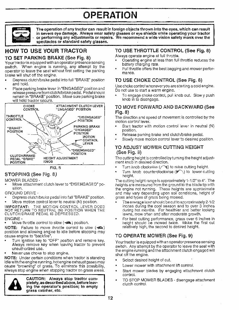
TO SET PARKING BRAKE (See Fig. 8)Your tractor is equipped with an operator presence sensingswitch. When engine is running, any attempt by theoperator to leave the seat without first setting the parkingbrake will shut off the engine.o Depress clutch/brake pedal into full "BRAKE" position
and hold.= Place parking brake lever in "ENGAGED" position and
release pressure from clutch/brake pedal. Pedalshouldremain in "BRAKE" position. Make sure parking brakewill hold tractor secure.
CHOKE "ATTACHMENT CLUTCH LEVERCONTROL "ENGAGED" POSiTiON
"HROTTLE "DISENGAGED"_'( POSITION
"BRAKE" PARKING 8RAKEPOSiTiON "ENGAGED"
POSITIONMOTION
LEVER
, "DISENGAGED"POSmON
CLUTCH/BRAKEPEDAL "DRIVE" HEIGHT ADJUSTMENTPOSITION KNOB ,
F_G. 8
STOPPING (See Fig= 8)MOWER BLADES -= Move attachment clutch lever to "D_SENGAGED" po-
sition.GROUND DRIVE -• Depress clutch/brake pedal into full "BRAKE" position.• Move motion control lever to neutral (N) position.IMPORTANT: THE MOTION CONTROL LEVER DOESNOT RETURN TO NEUTRAL (N) POSITION WHEN THECLUTCH/BRAKE PEDAL IS DEPRESSED.ENGINE -• Move throttle control to slow (,,_) position.NOTE: Failure to move throttle control to slow (,_,)position and allowing engine to idle before stopping maycause engine to "backfire".• Turn ignition key to "OFF" position and remove key.
Always remove key when leaving tractor to preventunauthorized use.
• Never use choke to stop engine.NOTE: Under certain conditions when tractor is standingidle withthe engine running, hot engine exhaust gases maycause "browning" of grass. To eliminate this possibility,always stop engine when stopping tractor on grass areas.
j_ CAUTfON: Always stop tractor com-A, _ _ above, before ieav- I
_r's position; to empty I
grass catcher, etc. .... I
TO USE CHOKE CONTROL (See Fig. 8)Use choke control whenever you are starting a cold engine.Do not use to start a warm engine.
o Te engage choke control, pul! knob out. Slowly pushknob in to disengage.
TO MOVE FORWARD AND BACKWARD (SeeFig. 8)The direction and speed of movement is controlled by themotion control lever.
Start tractor with motion control lever in neutral (N)position.
• Reiease parking brake and clutch/brake pedal.Slowly move motion control lever to desired position.
TO ADJUST MOWER CUTTING HEIGHT(See Fig. 8)
The cutting height is controlled by turning the height adjust-ment knob in desired direction.
, Turn knob clockwise (f"_) to raise cutting height.• Turn knob counterclockwise (P'-_) to lower cutting
height.The cutting height range is approximately 1-1/2" to 4". Theheights are measured from the ground to the blade tip withthe engine not running. These heights are approximateand may vary depending upon soil conditions, height ofgrass and types of grass being mowed.- The average lawn should be cut to approximately 2-1/2
inches during the cool season and to over 3 inchesduring hot months. For healthier and better lookinglawns, mow often and after moderate growth.
= For best cutting performance, grass over 6 inches inheight should be mowed twice. Make the first cutrelatively high; the second to desired height.
TO OPERATE MOWER (See Fig. 9)
Your tractor is equipped with an operator presence sensingswitch. Any attempt by the operator to leave the seat withthe engine running and the attachment clutch engaged willshut off the engine.
• Select desired height of cut.• Lower mower with attachment lift control.
• Start mower blades by engaging attachment clutchcontrol.
• TO STOP MOWER BLADES - disengage attachmentclutch control.
12

OP : ATION
_._ chaCAUTION:Do not operate the mower
without either the entire grass catcher,on mowers so equipped, or the dis-
rge guard in place.
NOTE: To protect hood from damage when transportingyour tractoron a truckor atrailer, be sure hood is closed andsecu red to tractor. Use an appropriate means of tying hoodto tractor (rope, cord, etc.).
ATTACHMENT CLUTCHLEVER "DISENGAGED"
• POSITION \
HEIGHT ___:'::_.
ADJUSTNENT / _::_ / _KNOB ,[ ///
"ENGAGED"POSITION ATTACHMENT
LIFT LEVER
NIGH POSiTiON
,,,',';
/7
GUARD
FIG. 9
TO OPERATE ON H_LLS
FiG. 10
BEFORE STARTING THE ENGINECHECK ENGINE OIL LEVEL (See Fig. 15)
The engine in your tractor has been shipped, from thefactory, already filled with summer weight oil.Check engine oil with tractor on level ground.Remove oil fill cap/dipstick and wipe Clean, reinsert thedipstick and screw cap tight, wait for a few seconds,remove and read oil level. If necessary, add oil until"FULU' mark on dipstick is reached. Do not ovedill.For cold weather operation you should change oil foreasier starting (See "OIL VISCOSITY CHART _in theCustomer Responsibilities section of this manual).
= To change engine oit, see the Customer Responsibili-ties section in this manual.
,, Choose the slowest speed before starting up or downhills.Avoid stopping or changing speed on hills.If slowing is necessan/, move throttle control lever toslower position.If stopping is absolutely necessary, push clutch/brakepedal quickly to brake position and engage parkingbrake.
,, Move motion control lever to neutral (N) position.IMPORTANT: THE MOTION CONTROL LEVER DOESNOT RETURN TO NEUTRAL (N) POSITION WHEN THECLUTCH!BRAKE PEDAL IS DEPRESSED.® To restart movement, slowly release parking brake and
clutch/brake pedal.,, Slowly move motion control lever to slowest setting.
Make all turns slowly.
TO TRANSPORT (See Fig. 10)When pushing or towing your tractor, be sure to disengagetransmission by placing freewheel control in freewheelingposition. Free wheel control is located at the rear drawbarof tractor.• Raise attachment lift to highest position with attach-
ment lift control.Pull freewheel control knob out and hold in position byinserting retainer spring into forward hole of control rod.Do not push or tow tractor at more than two (2) MPH.To reengage transmission, reverse above procedure.
13
ADD GASOLINE
o Fill fuel tank. Use fresh, clean, regular unleadedgasoline with a minimum of 87 octane. (Use of leadedgasoline will increase carbon and lead oxide depositsand reduce valve life). Do not mix oil with gasoline.Purchase fuel in quantities that can be used within 30days to assure fue! freshness.
iMPORTANT: WHEN OPERATING IN TEMPERATURES
BELOW 32°F(0°C), USE FRESH, CLEAN WINTER GRADEGASOLINE TO HELP INSURE GOOD COLD WEATHERSTARTING.
WARNING: Experience indicates that alcohol blendedfuels (called gasohol or using ethanol or methanol) canattract moisture which leads to separation and formation ofacids during storage. Acidic gas can damage the fuelsystem of an engine while in storage. To avoid engineproblems, the fue! system should be emptied before stor-age of 30 days or longer. Drain the gas tank, start theengine and let it run until the fue! lines and carburetor areempty. Use fresh fuel next season. See Storage Instruc-tions for additional information. Never use engine orcarburetor cleaner products in the fuel tank or permanentdamage may occur.
CAUTION: Fill to bottom of gas tankfiver neck. Do not overfill Wipe off anyspilled oil or fuel. Do not store, spill oruse gasoline near an open flame.

OPERATIONTO START ENGINE (See Fig. 9)When starting the engine for the first time or if the enginehas run out of fuel, it will take extra cranking time to movefuel from the tank to the engine.
Be sure freewheel control is in the transmission en-gaged position.
, Sit on seat in operating position, depress clutch/brakepedal and set parking brake.
° Place motion control lever in neutral (N) position.Move attachment clutch to "DISENGAGED" position.
- Move throttle controt to fast (,_) positionPull choke control out for a cold engine start attempt.For a warm engine start attempt the choke control maynot be needed.
Note: Before starting, read the warm and cold startingprocedures below., Insert key into ignition and turn key clockwise to"START"
position and release key as soon as engine starts. Donot run starter continuously for more than fi_een sec-onds per minute. If the engine does not start afterseveral attempts, push choke control in, wait a fewminutes and try again. If engine still does not start, puttthe choke control out and retry.
WARM WEATHER STARTING (50° F and above)• When engine starts, slowly push choke control in until
the engine begins to run smoothly. If the engine startsto run roughly, pull the choke control out slightly for afew seconds and then continue to push the cont._ol inslowly.
° The attachments and ground drive can now be used. Ifthe engine does not accept the load, restart the engineand allow itto warm up for one minute using the chokeas described above.
COLD WEATI4ER STARTING (50° F and below)• When engine starts, s!ow!y push choke control in until
the engine begins to run smoothly. Continue to pushthe choke control in small steps allowing the engine toaccept small changes in speed and load, until thechoke control is fully in. If the engine starts to runroughly, pull the choke control out slightly for a fewseconds and then continue to push the control inslowly. This may require an engine warm-up periodfrom several seconds to several minutes, dependingon the temperature.
HYDROSTATIC TRANSMISSION WARM UP
, Before driving the unit in cold weather, the transmis-sion should be warmed up as follows:• Be sure the tractor is on level ground.- Place the motion control lever in neutral.
Release the parking brake and let the clutch/brakeslowly return to operating position.
° Allow one minute for transmission to warm up.This can be done during the engine warm upperiod.
• The attachments can be used du ring the engine warm-up period after the transmission has been warmed upand may requirethe choke control be pulled out slightly.
NOTE: If at a high altitude (above 3000 feet) or in coldtemperatures (below 32 F)the carburetor fuel mixture mayneed to be adjusted for best engine performance. See 'qOADJUST CARBURETOR" in the Service and Adjustmentssection of this manual.
PURGETRANSMISSION
L& CAUTION: Never engage or disengage Ifreewheel lever while the engine is run-
ning.
To ensure proper operation and performance, it is recom-mended that the transmission be purged before operatingtractor for the first time. This procedure will remove anytrapped air inside the transmission which may have devel-oped during shipping of your tractor.IMPORTANT: SHOULD YOURTRANSMISSION REQUIREREMOVAL FOR SERVICE OR REPLACEMENT, ITSHOULD BE PURGED AFTER REINSTALLATIONBEFORE OPERATING THE TRACTOR.. Place tractor safely on level surface with engine off and
parking brake set., Disengage transmission by placing freewheel control
in freewheeling position (See "TO TRANSPORT" inthis section of manual).Sitting in the tractor seat, start engine. After the engineis running, move throttle control to slow (_) position.With motion control lever in neutral (N) position, slowlydisengage clutch/brake pedal.
, Move motion control lever to full forward position andhold for five (5) seconds. Move lever to full reverseposition and hold for five (5) seconds. Repeat thisprocedure three (3) times.
NOTE: During this procedure there will be no movement ofdrivewheels. The air is being removed from hydraulic drivesystem.* Move motion control lever to neutral (N) position. Shut-
off engine and set parking brake., Engage transmission by placing freewheel control in
driving position (See 'TO TRANSPORT" in this sectionof manual).
, Sitting in the tractor seat, start engine. After the engineis running, move throttle control to half (1/2) speed.With motion control lever in neutral (N) position, slowlydisengage clutch/brake pedal.
,, Slowly move motion control lever forward, after thetractor moves approximately five (5) feet, slowly movemotion control lever to reverse position. After thetractor moves approximately five (5) feet return themotion control lever to the neutral (N) position. Repeatthis procedure with the motion control lever three (3)times.
, Your tractor is now purged and now ready for normaloperation.
14

MOWING TiPS
=n
OPERATION
- Tire chains cannot be used when the mower housing isattached to tractor.
• Mower should be properly leveled for best mowingperformance. See "TO LEVEL MOWER HOUSING" inthe Service and Adjustments section of this manual.
- The left hand side of mower should be used for trim-ming.
,, Drive so that clippings are discharged onto the areathat has been cut. Have the cut area to the right of thetractor. This will 4"esult in a more even distribution ofclippings and more uniform cutting.
,, When mowing large areas, start by turning to the rightso that clippings will discharge away from shrubs,fences, driveways, etc. After one or two rounds, mowin the opposite direction making left hand turns untilfinished (See Fig. 1! ).
If grass is extremely tail, it should be mowed twice toreduce load and possible fire hazard from dried clip-pings. Make first cut relatively high; the second to thedesired height.
= Do not mow grass when it is wet. Wet grass will plugmower and leave undesirable clumps. Allow grass todry before mowing.
Always operate engine at full throttle when mowing toassure better mowing performance and proper dis-charge of material. Regulate ground speed by select-ing a low enough gear to give the mower cuttingperformance as well as the quality of cut desired.
,, When operating attachments, select a ground speedthat will suit the terrain and give best performance ofthe attachment being used.
.... 1t
f
u
MULCHING MOWING TIPSIMPORTANT: FOR BEST PERFORMANCE, KEEPMOWER HOUSING FREE OF BUILT-UP GRASS ANDTRASH. CLEAN AFTER EACH USE.• The special mulching blade will recut the grass clip-
pings many times and reduce them in size so that asthey fall onto the lawn they will disperse into the grassand not be noticed. Also, the mulched grass willbiodegrade quickly to provide nutrients for the lawn.Always mutch with your highest engine (blade) speedas this will provide the best recurring action of theblades.
Avoidcuttingyourlawnwhenitisweto Wet grass tendsto form clumps and interferes with the mulching action.The best time tO mow your lawn is the early afternoon.At this time the grass has dried and the newly' cut areawill not be exposed to the direct sun.For best results, adjust the mower cutting height so thatthe mower cuts off only the top one-third of the grassblades (See Fig. 12). For extremely heavy mulching,reduce your width of cut and mow slowly.
• Certain types of grass and grass conditions may re-quire that an area be mulched a second time tocompletely hide the clippings. When doing a secondcut, mow across or perpendicular to the first cut path.
, Change your cutting pattern from week to week. Mownorth to south one week then change to east to west thenext week. This will help prevent matting and grainingof the lawn.
RG. 12
FIG. 1t
15

l
CUSTO R PeN ES
MAINTENANCE SCHEDULEFILL IN DATESAS YOU COMPLETEREGULAR SERVICE
RACT0R
ENGI
i Check Brake OperationCheck Tire Pressure
Check for Loose Fasteners
Sharpen!Replace Mower Blades
Lubrication Chart
Check Battery Level/Recharge
Clean Battery and Terminals
Check Transaxle Cooling
Adjust Blade Be!t(s) Tension
Adjust Motion Drive Belt(s) Tension
Check Engine Oil Level
Change Engine Oi.I
Clean Air Filter
Clean Air Screen
Inspect Muffler/Spark Arrester
Replace Oil Filter (if equipped)
Clean Engine Cooling Fins
Replace Spark Plug
Replace Air Filter Paper Cartridge
iW.
_v'v"
' IV, i]
, I !I
1
v'
v, lv, i
/ i--[. i! J f
I ! ! ,2e /
I i , Iv'l I
I - Change more ottan when operating under a hea_5_load or in high ambient temperatures.
2 - Service more often when operating in dirty or d_sty ce_diflans.
3 - I| equipped with oil fitter, change oil every 50 hours,4 - Replace blades more often when mowing in sandy soil,
3_SERVICE DATES
i
i
__ i ! _
I L_
I_2__2_5 - If equipped with adjustabie system.6 - Not required if equippedwith maintenance-free baftery.7 _Tighten front axle pivot bolt to 35 ft.-Iba, maximum,
DOnot oveltlghten.
GENERAL RECOIVIMENDAT]ONS
The warranty on this tractor does not cover items that havebeen subjected to operator abuse or negligence. Toreceive full value from the warranty, operator must maintaintractor as instructed in this manual.
Some adjustments wil! need to be made periodically toproperly maintain your tractor.
All adjustments in the Service and Adjustments section ofthis manuai should be checked at least once each season.
Once,a year you should replace the spark plug, cleanor replace air filter, and check blades and belts forwear. A new spark plug and clean air filter assureproper air-fuel mixture and help your engine run betterand last longer.
BEFORE EACH USE
, Check engine oil level.
• Check brake operation.
= Check tire pressure.= Check for loose fasteners.
LUBRICAT!ON CHART
SP,NDLE ZERK ---qF'----------_ ['-'_SPINDLE ZERK(_
ENGINE (_
CCLUTCHPIVOT(S)
16
(_) SAE 30 OR lOW30 MOTOR OIL
(_D GENERAL PURPOSE GREASE
REFER TO CUSTOMER RESPONSIBILITIES "ENGINE" SECTION
IMPORTANT: DO NOT OIL OR GREASE THE PIVOT POINTSWHICH HAVE SPECIAL NYLON BEARINGS. VISCOUS LUBRI-CANTS WILL ATTRACT DUST AND DIRT THAT WILL SHORTENTHE LIFE OF THE SELF-LUBRICATING BEARINGS, IF YOUFEEL THEY MUST BE LUBRICATED, USE ONLY A DRY, POW-DERED GRAPHITE TYPE LUBRICANT SPARINGLY.

CUSTOM RESPO ILiTiESTRACTORAlways observe safety rules when performing any mainte-nance.
BRAKE OPERATION
If tractor requires more than six (6) feet stopping distanceat high speed in highest gear, then brake must be adjusted.(See "TO ADJUST BRAKE" in the Service and Adjust-ments section of this manual).
TIRES
, Maintain proper air pressure in all tires (See "PROD-UCT SPECIFICATIONS" on page 3 of this manual).
,, Keep tires free of gasoline, oil, or insect control chemi-cals which can harm rubber.
,, Aveid stumps, stones, deep ruts, sharp objects andother hazards that may cause tire damage.
NOTE: To seal tire punctures and prevent flat tires due toslow leaks, tire sealant may be purchased from your Iocaiparts dealer. Tire sealant also prevents tire dry rot andcorrosion.
BLADE CARE
For best results mower blades must be kept sharp. Re-place bent or damaged blades.
BLADE RE#OVAL (See Fig. 13)
• Raise mower to highest position to allow access toblades.
• Remove hex bolt, Iockwasher and flat washer securingblade.
, _nstall new or resharpened blade with trailing edge uptowards deck as shown.
Reassemble hex bolt, lock washer and flat washer inexact order as shown.
Tighten bolt securely (30-35 Ft. Lbs. torque).I_'_PORTANT: BLADE BOLT IS GRADE 8 HEAT TREATED.
NOTE: We do not recommend sharpening blade- but if youdo, be sure the blade is bs.lanced.
TO SHARPEN BLADE (See Fig. 14)
Care should be taken to keep the biade balanced. Anunbalanced blade will cause excessive vibration and even-tual damage to mower and engine.
The blade can be sharpened with a file or on a grindingwheel. Do not attempt to sharpen while on the mower.
,, To check blade balance, you wil! need a 5/8" diametersteel bolt, pin, or a cone balancer. (When using aconebalaneer, follow the instructions supplied with baFancer).
® Slide blade on to an unthreaded portion of the steel boltor pin and hold the bolt or pin parallel with the ground.if blade is balanced, it should remain in a horizontalposition. If either end of the blade moves downward,sharpen the heavy end until the blade is balanced.
NOTE: Do not use a nail for balancing blade. The lobes ofthe center hole may appear to be centered, but are not.
CENTERHOLE / /
/
BLADE
FtG. 14
BATTERY
Your tractor has a battery charging system which is suffi-cient for normal use. However, periodic charging of thebattery with an automotive charger will extend its life.
,, Keep battery and terminals clean.
o Keep battery bolts tight.
,, Keep small vent holes open.
Recharge at 6-10 amperes for 1 hour.
TO CLEAN BATTERY AND TERMINALS
Corrosion and dirt on the battery and terminals can causethe battery to "leak" power.
• Remove terminal guard.
• Disconnect BLACK battery cable first then REDbattery cable and remove battery from tractor.
• Rinse the battery with plain water and dry.
• C}ean terminals and battery cable ends with wirebrush until bright.
• Coat terminals with grease or petroleum jelly.
= Reinstall battery (See "CONNECT BATTERY" in theAssembly section of this manual).
PIG, !3
17

CUSTOMER RESPONSIBILITIESV-BELTS
Check V-belts for deterioration and wear after 100 hours ofoperation and replace if necessary. The belts are notadjustable. Replace belts if they begin to slip from wear.
TRANSAXLE COOLING
The fan and cooling fins of transmission should be keptclean to assure proper cooling.
Do not attempt to clean fan or transmission while engine isrunning or while the transmission is hot.
Inspect cooling fan to be su re fan blades are intact andclean.
Inspect cooling fins for dirt, grass clippings and othermaterials. To prevent damage to seals, do not usecompressed air or high pressure sprayer to cleancooling fins.
TRANSAXLE PUMP FLUID
The transaxle was sealed at the factory and fluid mainte-nance is not required for the life of the transaxle. Should thetransaxle ever leak or require servicing, contact your near-est authorized service center/department.
ENGINE
LUBRICA'NON
Only use high quality detergent oil rated ,_,ithAP] serviceclassification SF, SG, or SH. Select the oil's SAE viscositygrade according to your expected operating temperature.
_20o 0o 30 _ 32 ° 40 ° 60 ° 80 ° 100 °
.3oo _2oo __oo 0o 10° 2o° 3oo 40°RANGE ANTfCIPATED BEFORE NEXT OIL CHANGE
NOTE: Although multi-viscosity oils (5W30, 10W30 etc.)improve starting in cold weather, these multi-viscosity oilswill result in increased oil consumption when used above32°F. Check your engine oil level more frequently to avoidpossible engine damage from running low on oil
Change the oil after every 25 hours of operation or at leastonce ayear if the tractor is not used for 25 hours in one year;
Check the crankcase oil level before starting the engineand after each eight (8) hours of operation. Tighten oil fillcap/dipstick securely each time you check the oil level.
TO CHANGE ENGINE OIL (See Fig. 15)
Determine temperature range expected before oil change,All oil must meet AP! service classification SF, SG or SH.
• Be sure tractor is on level surface.
• Oil will drain more freely when warm., Catch oil in a suitable container.
• Remove oil fill cap/dipstick. Be careful not to allow dirtto enter the engine when changing oil.
• Remove drain plug.
o
w
After oil has drained completery, replace oil drain plugand tighten securely.
Refill engine with oil through oil fill dipstick tube. Pourslowly. [30 not overfill. For approximate capacity see"PRODUCT SPECIFICATIONS" on page 3 of thismanual.
• Use gauge on oil fill cap/dipstick for checking level. Besure dipstick cap is tightened securely for accuratereading. Keep oil at "FULL" line on dipstick.
OILDRAINPLUG
AIR SCREEN
18
OIL FILLCAP/DIPSTSICK
CLEAN AiR SCREEN (See Fig. 15)
Air screen musl be kept free of dirt and chaff to preventengine damage from overheating. Clean with a wire brushor compressed air to remove dirt and stubborn dried gumfibers.
AHR FILTER (See Fig. 16)
Your engine will not run properly using a dirty air filter.Clean the foam pre-cleaner after every 25 hours of opera-tion or every season. Service paper cartridge every 100hours of operation or every season, whichever occurs first.
Service air cleaner more often under dusty conditions.
o Remove knob(s) and cover,TO SERVICE PRE-CLEANER
- Slide foam pre-cleaner off cartridge.
• Wash it in liquid detergent and water.
Squeeze it dry in a clean cloth.
Saturate it in engine oil. Wrap it in clean, absorbentcloth and squeeze to remove excess oil.
If very dirty or damaged, replace pre-cleaner.
Reinstall pre-cleaner over cartridge.
Reinstall cover and secure with knob(s).TO SERVICE CARTRIDGE
• Remove wing nuts and cartridge plate.
Carefully remove cartridge to prevent debris from en-tering carburetor.
• Clean cartridge bytapping gently on flat surface. Ifverydirty or damaged, replace cartridge.
• Reinstall cartridge plate, wing nuts, precleaner, coverand secure with knob(s).
IMPORTANT: PETROLEUM SOLVENTS, SUCH ASKEROSENE, ARE NOT TO BE USED TO CLEAN THECARTRIDGE. THEY MAY CAUSE DETERIORATION OFTHE CARTRIDGE. DO NOT OIL CARTRIDGE. DO NOTUSE PRESSURIZED AIR TO CLEAN OR DRYCARTRIDGE.
CUSTOMER R
KNOB
FOAM
F_G. 16
PLATE
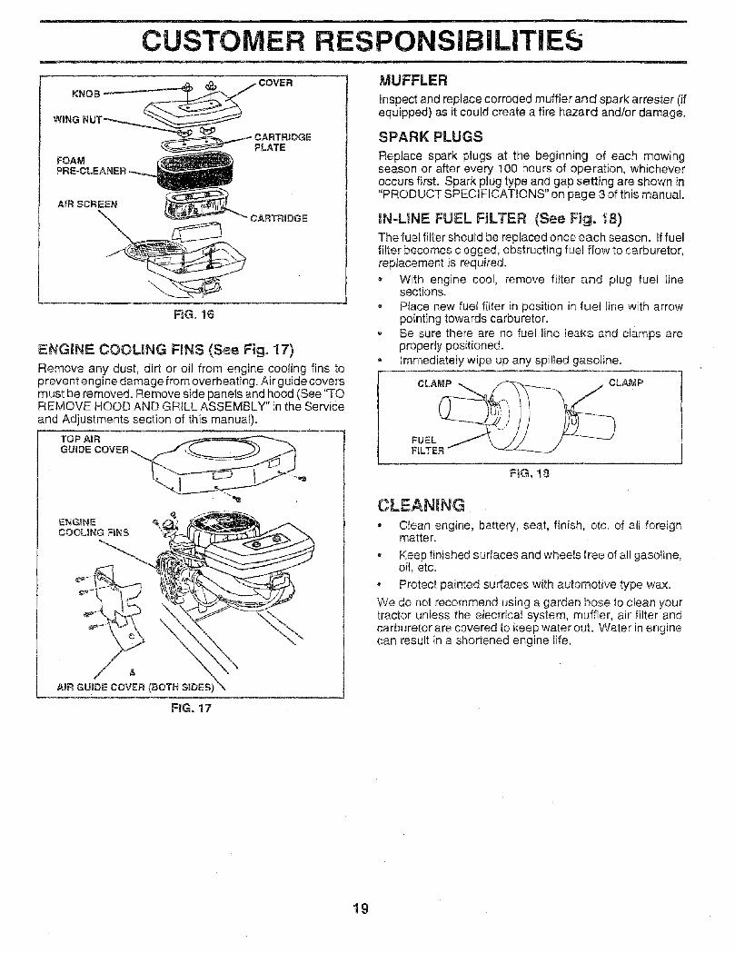
ENGINE COOLING F{NS (See Fig. 17)
Remove any dust, dirt or oiJ from engine cooling fins toprevent engine damage from overheating. Air guide coversmust be removed. Remove side panels and hood (See 'qOREMOVE HOOD AND GRILL ASSEMBLY" in the Serviceand Adjustments section of this manual).
TOP AiR
GUIDE COVER _.
P ;IBILITIES
MUFFLER
Inspect and replace corroded muffler and spark arrester (ifequipped) as it could create a fire hazard and/or damage.
SPARK PLUGS
Replace spark plugs at the beginning of each mowingseason or after every 100 hours of operation, whicheveroccurs first. Spark plug type and gap setting are shown in"PRODUCT SPECIFICATIONS" on page 3 of this manual
iN-LINE FUEL FBLTER (See Fig. 18)Thefue{ filter should be replaced once each season. If fuelfilter becomes clogged, obstructing fue] flow to carburetor,replacement is required.
With engine cool, remove filter and plug fuel Jinesections.
, Place new fue! filter in position in fuel line with arrowpointing towards carburetor.Be sure there are no fuel line leaks and clamps areproperly positioned.
• Immediately wipe up any spilled gasoline.
CLAMP
ENGINECOOLING FiNS
/AiR GUIDE COVER (BOTH S_DES)
FIG. 18
CLEANING• Clean engine, battery, seat, finish, etc. of all foreign
matte r.
, Keep finished surfaces and whee!s free of al! gasoline,oil, etc.
Protect painted surfaces with automotive type wax.
We do not recommend using a garden hose to clean yourtractor unless the electrical system, muffler, air filter andcarburetor are covered to keep water out. Water in enginecan result in a shortened engine life,
FiG. 17
19

SERVICE AND ADJUSTMENTS
CAUTION" BEFORE PERFORMING ANY SERVICE OR ADJUSTMENTS:
° Depress clutch!brake pedal fully and set parking brake.* Place motion control lever in neutral (N) position.* Place attachment clutch in "DISENGAGED" position.= Turn ignition key "OFF" and remove key.- Make sure the blades and all moving parts have completely stopped., Disconnect spark plug wire from spark plug and place wire where it cannot come in contact
with plug.
TRACTOR
TO REMOVE MOWER (See Fig. 20)
Mover will be easier to i'emove from the right side of tractor.
- Place attachment clutch in "DISENGAGED" position.
o Move attachment lift lever forward to lower mower to itslowest position.
° Roll belt off engine pulley.
, Disconnect clutch rod from clutch lever by removingretainer spring.
- Disconnect anti-sway bar from chassis bracket byremoving retainer spring.
- Disconnect suspension arms Irom rear deck bracketsby removing retainer springs.
Disconnect front links from deck by removing retainersprings.
= Raise lift lever to raise suspension arms. Slide mowerout from under tractor.
IMPORTANT: IF AN ATTACHMENT OTHER THAN THEMOWER IS TO BE MOUNTED TO THE TRACTOR,REMOVE THE FRONT LINKS.
TO INSTALL MOWER (See Fig, 20)
, Raise attachment lift !ever to its highest position.
, Slide mower under tractor with discharge guard to rightside of tractor.
Lower lift lever to its lowest position.
,, Install mower in reverse order of removal instructions.
CLUTCH LEVER
RETAINERSPRING
ENGINE
SUSPENSION FRONTLINK
RETAINER
3OTHSIDES}
RETAINERSPRING
ANTI-SWAY BARRETAINERSPRINGS(BOTH SIDES)
FIGo 20
20

SERVICE ADJUSTMENTS- n
TO LEVEL MOWER HOUSING
Adjust the mower while tractor is parked on level ground ordriveway. Make sure tires are properly inflated (See"PRODUCT SPECIFICATIONS" on page 3 of this manual).If tires are over or underinflated, you will not properly adjustyour mower.
SIDE-TO-SIDE ADJUSTMENT (See Figs. 21 and 22)• Raise mower to its highest position.
,, At the midpoint of both sides of mower, measure heightfrom bottom edge of mower to ground. Distance"A" onboth sides of mower shou!d be the same or within 1/4"of each other.
- If adjustment is necessary, make adjustment on oneside of mower only.
- To raise one side of mower, tighten lift link adjustmentnut on that side.
To lower one side of mower, loosen lift link adjustmentnut on that side.
No'rE: Each full turn of adjustment nut wilt change mowerheight about 1/8".
, Recheck measurements after adjusting.
BOTTOM EDGE BOTTOM EDGEOF MOWER TO OF MOWER TOGROUND GROUND
GROUND LINE A
FIG. 21
_\ USPENS;ON
ARM
\LIFT LINKADJUSTMENT NUT
FIG. 22
FRONT-TO-BACK ADJUSTMENT (See Figs. 23 and 24)_MPORTANT: DECK MUST BE LEVEL SIDE-TO-SIDE. IFTHE FOLLOWING FRONT-TO-BACK ADJUSTMENT ISNECESSARY, BE SURE TO ADJUST BOTH FRONT LINKSEQUALLY SO MOWER WILL STAY LEVEL SiDE-TO-SIDE.
To obtain the best cutting results, the mower Rousingsr_ou!dbe adjusted so that the front is approximatePy !/8" to1/2" lower than the rear when the mower is in its highestposition.Check adjustment on right side of tractor. Measure dis-tance"D" directly in front and behind the mandrel at bottomedge of mower housing as shown.- Before making any necessary adjustments, check that
both front links areequal in length. Both links should beapproximately 10-3/8".
- If links are not equal in length, adjust one link to sameJength as other link.
,, To lower front of mower loosen nut "E" on both frontlinks an equal number of turns.Wr_en distance "D" is !/8" to 1/2" lower at front thanrear, tighten nuts "F" against trunnion on both frontiinks.
= To raise front of mower, loosen nut"F" from trunnion onboth front links. Tighten nut "E" on bDth front links anequal number of turns.
= When distance "D" is 1/8" to 1t2" lower at front thanrear, tighten nut "F" against trunnion on both front links.
, Recheck side-to-side adjustment.
F_G, 23
BOTH FRONT LINKS MUST BE EQUAL IN LSNGTH
NUT "F"
FRONT LINKS TRUNNION
NUT"E"
21 FiG, 24

NO IMAGE
PAG ES 22-25

SERVICE A ADJUSTMENTSTO ADJUST CARBURETOR (See Figs. 34 &35)The carburetor has been preset at the factory andadjust-ment should not be necessary. However, minor adjust-ment may be required to compensate for differences in fue!,temperature, altitude or load. If the carburetor does needadjustment, proceed as follows:
In general, turning the mixture screw in (clockwise) de-creases the supply of fuel to the engine giving a leaner fuel/air mixture. Turning the mixture screw out (counterclock-wise) increases the supply of fuel to the engine giving aricher fuel/air mixture.
BMPORTANT: DAMAGE TO THE NEEDLES AND THESEATS IN CARBURETOR MAY RESULT iF SCREW ISTURNED IN TOO TIGHT.
PRELIMINARY SETTING -
• Be sure you have a clean air filter, and the throttlecontrol cable and choke are adjusted properly (seeabove).
With engine off turn idle mixture screw in (clockwise)closing it finger tight and then turn out (counterclock-wise) 1-1/4 to 1-1/2 turns.
FINAL SETTING -
Start engine and allow to warm for five minutes. Makefinal adjustments with engine running and shift/motioncontrol lever in neutral (N) position.
• With throttle control lever in slow (,_) position, holdthrottle lever against idle speed screw and adjust idlespeed screw to obtain 1200 to 1400 RPM.
While still holding throttle lever against idle speedscrew, turn idle mixture screw in (cleSkwise) untilengine begins to die and then turn out (counterclock-wise) until engine runs rough. Turn screw to a pointmidway between those two positions.
- Continue to hold throttle iever against idle speed screwand adjust idle speed screw to obtain 900 to 1200RPM. Release throttle lever.
ACCELERATION TEST -
Move throttle control lever from slow (_.) to fast (4_)position. If engine hesitates or dies, turn idle mixturescrew out (counterclockwise) I/8 turn. Repeat testand continue to adjust, if necessaFy, until engine accel-erates smoothly.
High speed step is factory adjusted. Do not adjust -damage may result.
IMPORTANT: NEVER TAMPER WITH THE ENGINEGOVERNOR, WHICH IS FACTORY SET FOR PROPERENGINE SPEED. OVERSPEEDING THE ENGINE ABOVETHE FACTORY HIGH SPEED SETTING CAN BEDANGEROUS. IF YOUTHINKTHEENGINE-GOVERNEDHIGH SPEED NEEDS ADJUSTING, CONTACT YOURNEAREST AUTHORIZED SERVICE CENTER/DEPARTMENT, WHICH HAS PROPER EQUIPMENTANDEXPERIENCE TO MAKE ANY NECESSARYADJUSTMENTS.
IDLE SPEEDSCREW
IDLE MIXTURESCREW
THROTTLELEVER
FIG. 34
THROTTLELEVER
FIGo 35
, 26

STORAGE
Immediately prepare your tractor for storage at the end ofthe season or if the tractor will not be used for 30 days ormore.
CAUTION: Never store the tractor withgasoline in the tank inside a buildingwhere fumes may reach an open flameor spark, Allow the engine to coolbefore storing in any enclosure,
TRACTOR
Remove mower from tractor for winter storage. Whenmower is to be stored for a period of time, clean it thor-oughly, remove al! dirt, grease, leaves, etc. ,Store in aclean, dry area.
Clean entire tractor (See "CLEANING" in the CustomerResponsibilities section of this manual).
, inspect and replace belts, if necessary (See belt re-placement instructions in the Service and Adjustmentssection o'; this manual).
,, Lubricate as shown in the Customer Responsibilitiessection of this manual.
Be sure that all nuts, bolts and screws are securelyfastened. Inspect moving parts for damage, breakageand wear. Replace if necessary.
TOuch up all rusted or chipped paint surfaces; sandlightly before painting.
BATTERY
Fully charge the bakery for storage.
After a period of time in storage, battery may requirerecharging.
To help prevent corrosion and power leakage duringlong periods of storage, battery cables should bedisconnected and battery cleaned thoroughly (see "TOCLEAN BATTERY' AND TERMINALS" in the Cus-tomer Responsibilities section of this manual).
,, After cieaning, leave cables disconnected and placecables where they cannot come in contact with batteryterminals.
Be sure battery drain tube is securely attached,
If battery is removed from tractor for storage, do notstore battery directly on concrete or damp surfaces.
ENGINE
FUEL SYSTEM
IMPORTANT: IT IS IMPORTANT TO PREVENT GUMDEPOSITS FROM FORMING IN ESSENTIAL FUELSYSTEM PARTS SUCH AS CARBURETOR, FUEL FILTER,FUEL HOSE, OR TANK DURING STORAGE. ALSO,EXPERIENCE INDICATES THAT ALCOHOL BLENDEDFUELS (CALLED GASOHOL OR USING ETHANOL ORMETHANOL) CAN ATTRACT MOISTURE WHICH LEADSTO SEPARATION AND FORMATION OF ACIDS DURINGSTORAGE. ACIDIC GAS CAN DAMAGE THE FUELSYSTEM OF AN ENGINE WHILE tN STORAGE.
Orain the fuel tank.
Start the engine and let it run until the fuel lines andcarburetor are empty.
• Never use engine or carburetor cleaner products in thefue! tank or permanent damage may occur.Use fresh fuel next season.
NOTE: Fuel stabilizer is an accepl_.ble alternative inminimizing the formation of fuel gum deposits during stor-age. Add stabilizer to gasoline in fuet tank or storagecontainer. Always foilow the mix ratio found on stabilizercontainer. Run engine at least 10 minutes after addingstabilizer to allow the stabilizer to reach the carburetor. Donot drain the gas tank and carbu rotor if using fuel stabilizer.
ENGINE O_L
Drain oi! (with engine warm) and replace with clean engineoil. (See "ENGINE" in the Customer Responsibilitiessection of this manual).
CYLINDERS
, Remove spark plug(s).
o Pour one ounce of oil through spark plug hole(s) intocylinder(s).
Turn ignition key to "START" position for a few secondsto distribute oi!.
Replace with new spark plug(s).
OTHERo Do not store gasoline from one season to another.
Replace your gasoline can if your can starts to rust.Rust and/or dirt in your gasoline win cause problems.
, If possible, store your tractor indoors and cover it togive protection from dust and dirt.
- Cover your tractor with a suitable protective cover thatdoes not retain moisture. Do not use plastic. Plasticcannot breathe which allows condensation to form andwill cause your tractor to rust.
IMPORTANT: NEVER COVERTRACTOR WHILE ENGINEAND EXHAUST AREAS ARE STILL WARM.
27

TRO BL OOTING POINTS
PROBLEM
Wil! not start
Hard to start
Engine will not turn over
Engine Clicks but will notstart
Loss of power
Excessive vibration
CAUSE
1. Out of fuel.2. Engine not "CHOKED" property.3. Engine flooded.4. Bad spark plug,5. Dirty air filter.6. Dirty fuel filter.7. Waterin fuel,
.8,
9,Loose or damaged wiring.Carburetor out of adjustment,
10. Engine valves out of adjustment,
1. Dirty air filter.2. Bad spark plug,3. Weak or dead battery.4. Dirty fuel filter.5. Stale or dirty fuel.6. Loose or damaged wiring.7. Carburetor out of adjustment.
8, Engine valves out of adjustment.
1. Clutch/brake pedal not depressed.2. Attachment clutch is engaged.3. Weak or dead battery.4. Blown fuse.5. Corroded battery terminals.6. Loose or damaged wiring.7. Faulty ignition switch.8. Fauity solenoid or starter,9. Faulty operator presence switch(es).
1. Weak o_"dead battery.2. Corroded battery terminals,3. Loose or damaged wiring.4. Faulty solenoid or starter,
1. Cutting too much grass/too fast,2, Throttle in "CHOKE" position.3, Buildoup of grass, leaves and trash under mower,4, Dirty air filter.5. Low oil level/dirty oil.6, Faulty spark plug,7. Dirty fuel filter.8. Stale or dirty fuel.g. Water in fuel.
CORRECTION
1, Fill fuel tank.
2, See q-O START ENGINE" in Operation section.3, Wait several minutes before attempting to start.4. Replace spark plug.5. Clean/replace air filter,6. Replace fuel filter.7, Drain fuel tank and carburetor, refill tank with fresh
gasoline and replace fuel filter.8. Check all wiring.9, See 'q'o Adjust Carburetor" in Service Adjustments
section.10. Contact an authorized service center/department,
1, Clean/replace air filter.2, Replace spark plug.3, Recharge or replace battery.4. Replace fuel filter.5. Drain fuel tank and refill with fresh gasoline.6, Check all wiring.7. See "To Adjust Carburetor" in Sen,ice Adjustments
section,
8. Contact an authorized sen,ice center/department.
1. Depress clutch/brake pedal.2. Disengage attachment clutch.3, Recharge or replace battery,4. Replace fuse.5. Clean battery terminals.6. Check all wiring.7. Check/replace ignition switch.8. CheckJreplace solenoid orstarter.9. Contact an authorized service center!department.
1. Recharge or repiace battery.2. Clean battery terminals.3. Check all wiring,4. Check!replace solenoid or starter.
1. Set in "Higher Cut" position/reduce speed.2. Adjust throttle control.3. Clean underside of mower housing.
10. Spark plug wire loose,11. Dirty engine air screen/fins.12. Dirty/clogged muffler.13. Loose or damaged wiring,14. Carburetor out of adjustment.
15. Engine valves out of adjustment.
1, Worn, bent or loose blade.2. Bent blade mandrel,
3. Loose/damaged part(s).
4. Clean/replace air filter.5. Check oil level/change oil6. Clean and regap or change spark plug.7. Replace fuel filter,8, Drain fuel tank and refill with fresh gasoline.9. Drain fuel tank and carburetor, refill tank with fresh
gasoline and replace fuel filter.10. Connect and tighten spark plug wire.11, Clean engine air screen/fins.12. Clean/replace muffler.
13. Check all wiring.14, See "To Adjust Carburetor" in Service Adjustments
section,
15. Contact an authorized service center/department.
1. Replace blade. Tighten blade bolt.2. Replace blade mandrel,3. Tighten loose part(s). Replace damaged parts.
28

TROUBLESHOOTI POINTS
PROBLEM
Engine continues to runwhen operator leaves seawith attachment clutchengaged
Poor cut - uneven
Mower blades will notrotate
Poor grass discharge
CAUSE
1. Faulty operator-safety presence control system.
1. Worn, bent or loose blade.2. Mower deck not level.
3. Buildup of grass, leaves, and trash under mower.4. Bent blade mandrel',
5, Clogged mower deck vent holes from buildup ofgrass, leaves, and trash around mandrels.
1, Obstruction in clutch mechanism.
2. Worn/damaged mower drive belt.3. Frozen idler pulley.4. Frozen blade mandrel.
1. Engine speed too slow.2. Travel speed too fast.
CORRECTION
1. Check wiring, switches and connections. If notcorrected, contact an authorized service center/department.
1. Replace blade. Tighten blade bolt.2. Level mower deck,
3. Clean underside o| mower housing.4. Replace blade mandrel5. CIean around mandre{s to open vent holes.
1. Remove obstruction.
2. Replace mower drive bait.3. Replace idler pulley.4. Replace blade mandrel.
1. Place throttle control in "FAST" position.2. Shift to slower speed.
3. Wet grass.4. Mower deck not level.5. Low/uneven tire air pressure.6. Worn, bent or loose blade.7. Buildup of grass, leaves and trash under mower.8. Mower drive belt worn,
9. Blades improperly installed.t0. Improper blades used.11. Clogged mower deck vent holP.s ;Tom buildup of
grass, leaves, and trash around mandrels.
3. Allow grass to dry before mowing.4. Level mower deck.5. Check tires for proper air pressure.6. Replace/sharpen blade. Tighten blade bolt.7. CIean underside of mower housing.8. Replace mower drive belt.9. Reinstall blades sharp edge down,
10. Replace with blades listed in this manual.11. Clean around mandrels to open vent holes.
Headlight{s) not working(if so equipped}
Battery witl not charge
Loss of drive
m
Engine "backfires"when turning engine"OFF"
1. Switch is "OFF".
2. Bulb(s) burned out.3. Faulty light switch.4. Loose or damaged wiring.5, Blown fuse.
1. Bad battery cell(s).2. Poor cable connections.
3. Faulty regulator (if so equipped).4. Faulty alternator.
1, Freewheel control in %isengaged" position.2. Motion drive belt worn, damaged, or broken,3. Air trapped in transmission during shipment
or servicing.
1. Engine throttle controJ not set at 'SLOW"position for 30 seconds before stopping engine.
1. Turn switch "ON".
2. Replace bulb(s).
3. CheckJ'replace light switch.4, Check wiring and connections.5. Replace fuse.
1, Replace battery.2, ChecWclean all connections.
3. Replace regu{ator.4. Replace alternator.
1. Place freewheel control in "engaged" position.2. Replace motion drive belt.3. Purge transmission.
1. Move throttle control to "SLOW" position and allowto idle for 30 seconds before stopping engine.
29

SERVICE NOTES
3O

SCHEMATIC
TRACTOR - - MODEL NUMBER 917.258572
RED BLACK ,.
O gbFUSE 30 AMP.
frO,O;-I I fl " I
! (PEDAL UP)
BLACK
METER
........ I I
..... J
SOLENOID
WHITE
I1 r
_ARL) FED
........._ I WHITE
)G L ("')-
SWITCH I/77
IF
(OPTIONAL)
RED
I i k 'qI , BLACK I
STARTER
BLACK (_ IGNITIONUNIT
I
BLACK
SEAT SWITCH(NOT OCCUPIED)
f
I
BLUE
ORANGE
t-
I BLACKT
CHARGING SYSTEM OUTPUT3 AMP _ @ 360,0 RPM
I
GROUNDINGCONNECTOR
TWIN CYL. ENGINES)28 VOLTS AC MIN. @ 3600 RPM(CHARGING SYSTEM D SOONNECTEO)
I
IGNITION SWITCH
POSITION
OFF
RUN/L[GHT
RUN
START
CIRCUIT I "MAKE"
G+M+LI NONE ,
B+L _ A+YB + L / NONE
B+L÷S I NONE
NOTE
YOUR TRACTOR ISEQUIPPED WITH A SPECIALALTERNATOR SYSTEM.THE LIGHTS ARE NOTCONNECTED TO THEBATTERY, BUT HAVE THEIROWN ELECTRICAL SOURCE.BECAUSE OF THIS, THEBRIGHTNESS OF THE LIGHTSWILL CHANGE WITH ENGINESPEED. AT IDLE THE LIGHTSWILL DIM. AS THE ENGINE ISSPEEDED UP, THE LIGHTSWILL BECOME THEIR BRIGHTEST.
LIGHTING SYSTEM OUTPUT DIODE i ALTERNATOR5 AMP AC @ 3600 RPM _ i
m I j
14 VOLTS AC MIN, @ 3600 RPM (LIGHTS OFF}
HEADLIGHTS
BROWN
O ©NON-REMOVABLE REMOVABLE
CONNECTIONS CONNECTIONS /-)
WIRING INSULATED CLIPSNOTE: IF WIRING INSULATEDCLIPS WERE REMOVED FORSERVICING OF UNIT, THEYSHOULD BE REPLACED TOPROPERLY SECURE YOUR WIRING.
31

REPAIR PARTSTRACTOR- - MODEL NUMBER 917.258572
ELECTRICAL
1
89
7
19
2O
1
I
• I
42
, 41
12
/1
I
I
II '
t,
]I
Zi
\\
\
\
I
/
1
I
1/
/
/
/1
!
32

REPAIR PARTSTRACTOR = o MODEL NUMBER 917.258572
ELECTRICAL
KEY PARTNO. NO. DESCRaPTION
1 1449262 747604123 STD5510254 STD5511256 STD5410257 7697J8 7603J9 109596X
10 14521111 15010912 14576916 15366419 STD55112520 7335040021 14743022 4152J24 4799J25 14614826 108824X28 14549129 121305X3O 14O3O131 124211X32 14122633 109310X4O 156442,41 7111040842 13156343 14567344 7364040045 121433X52 14194055 1749050870 140413
BatteryBolt, Hex 1/4-20 x 3/4Washer 9/32 × 5/8 x 16 GaugeWasher, Lock 1/4Nut, Hex 1/4-20TubeTray, BatteryClamp, HoseBolt, Btr Front 1/4-20 x 7-1/2Holddown Battery Front MountNut, Push Nylon Battery Front 1/4Switch Interlock Push-inWasher, Lock 1/4Nut, Hex, Jam 1/4-20
Harness, Light Socket (w/4152J)Light BulbCable, BatteryCable, BatteryFuseCable, GroundSwitch, SeatSwitch, Ignition 4 PositionNut, IgnitionCover, Ignition SwitchKey, Molded, CraftsmanHarness, IgnitionBolt BIk Fin Hex 1/4-20 UNC x 1/2Cover, TerminalSolenoidNut Keps BIk Hex 1/4-20 UNCAmmeter Rectangular 6 AmpProtection Wire Loop (Hour Meter)Screw Thdrol 5/16-18 x 1/2Harness Engine B&S/Tec Dual
NOTE: All component dimensions given in U.S. inches1 inch = 25.4 mm
33

REPAIR PARTSTRACTOR - - MODEL NUMBER 917.258572
CHASSIS AND ENCLOSURES
28
58 12
14
31
37
Ii
37
20 23
54
2 55
/. 57
142_3
j3
3 /374
14
34

REPAIR PARTSTRACTOR = - MODEL NUMBER 917.258572
CHASSIS AND ENCLOSURES
KEY PARTNO. NO. DESCRIPTION
1 1595272 1403563 174906124 STD5510255 1552729 150156X011
10 STD53371011 15592712 145660.13 15593614 1749060817 144983X55818 126938X20 15643723 124028X25 1913131226 STD54143728 145198X55829 15521730 151287X55831 13997637 1749050838 13988639 13988751 7380040052 1909141653 14520154 170308_455 14520257 STD55250758 14054760 7214060664 15479871 7368040074 STD541437140 158418142 156095143 154966144 154207145 156524147 74760412
Chassis, STL StampingDrawbarScrew, Thd., Roll. 3/8-16 x 3/4 Type TTWasher 13/32 x 3/4 x 16 GaugeBumper Hood/DashDash, SiikscreenedBolt, Carriage 3/8-16 x 1Panel, Dash, LHClip Tinnerman Grille P/LPanel, Dash, RHScrew, Thd., Roll. 3/8-16 x 1/2 Type TTHood AssemblyBumber HoodPlate Mtg Battery Fuel TankBushing, Snap, Nylon, Fuel LineWasher 13/32 x 13/16 x 12 GaugeLocknut, Hex, with Insert 3/8-16 UNCGrille, W!Clips MS-558Lens, GrilleFender/FootrestBracket, Fender/SupportScrew, Thdrol. 5/16-18 x 1/2 TYTPivot Bracket Assembly, LH, Mower, RearPivot Bracket Assembly, RH, Mower, RearNut Lock W!Insert 1/4 - 20 UNCWasher 9/32 X 7/8 X 16 Ga.Bracket Grille Pickoff LHScrew, Hex Head, Spider!ock #8 x 7/8 ABBracket Grille Pickoff RHBolt FinHex 1/4 -20 UNC X.75Air Duct P!L 18HP B&S Opp. TwinBolt Rdhd Sqnk 3/8-16 UNC x 3/4Dash Lower STLTNut Crownlock 1/4-20 UNCNut Crownlock 3/8-16 UNCBracket Suspension FrontPlate Reinforcement STLTBackrest Swaybar ChassisBracket Footrest STLTRod Pivot Chassis/HoodBolt, Hex Hd 1/4-20 UNC x 3/4
NOTE: All component dimensions given in U.S. inches1 inch = 25.4 mm
35

SEE PARTS LIST

REPAIR PARTSTRACTOR - - MODEL NUMBER 917,258572
ENGINE
2
15
©
/
3g
32 31
17
1S
5
29
OPTIONAL EQUIPMENT
Spark Attester
4O

REPAIR
ENGINE
PARTSTRACTOR - = MODEL NUM BER 917°258572 .
KEY PARTNO. NO. DESCRIPTION
1 1512732 177204103 .......
4 1497235 1440696 1440687 1381298 15O176
10 14555211 STD551125!2 STD52250713 27225014 1328033615 1320030016 STD55123717 1749062423 15612325 14599626 7392060027 15292729 13718031 15710332 15597133 123487X34 106082X'35 1749051237 8543R38
39 109227X4O 3645J41 13927781 128861
Control Throt Paddle 32 22Screw Hex Thd Cut 1/4-20x5/8 TEngine (See Breakdown) BriggsModel No. 42E707-1631-01Muffler ExhaustExhaust Asm. LeftExhaust Asm. RightClamp Tube Double EngineBolt 5/16 - 18 UNC X 3/4 W/SemsHeat Shield LtWasher Lock Hvy. Helical 1/4Bolt Fin Hex 1/4-20 x3/4Gasket MufflerNipple Pipe 4-1/2"Elbow Std 90 Degree 3/8-18 NptWasher Lock Ext Tooth 3/8Screw Thdrol 3/8-16xl -1/2 TyttShield BrowningControl ChokeNut Keps 3/8-24 UnfScrew TT #10-32 x 5 x 3/8 FlangeArrestor SparkTank Fuel 3 50 RearCap Fuel Guage STLTClamp Hose BIkSpacer PadScrew Thdrcl 5/16-18 x 3/4 TYTLine FuelPlug Oil Drain (Order From EngineManufacturer)Pad idler 1.75 x ,75 x .06BushingStem Tank FuelNut, Flange 1/4-20 Starter Nut
NOTE: All component dimensions given in U.S. inches1 inch = 25.4 mm
41

REPAIR PARTSTRACTOR = - MODEL NUMBER 917.258572
MOWER LIFT
25 2423
5 49
3O
3
\26
8/!i /
i i'
I I"
I I'
i'.... I'
5
19
13
32
32
2O
42

REPAIR PARTSTRACTOR == MODEL NUMBER 917,258572
MOWER LIFT
KEY PARTNO. NO. DESCRiPTiON
1 159460 Wire Asm, Inner/Sprg w/Plunger2 159471 Shaft Asm. Lift3 105767X Pin Groove4 12000002 E Ring #5133-625 19211621 Washer 21/32xl x21Ga.6 120183X Bearing Nylon7 125631X Grip Handle Fluted8 122365X Button Plunger Read
11 139865 Link Lift Lh Fixed Length12 139866 Link Lift Rh Fixed Length13 STD624008 Retainer Spring15 127218 , Link Front16 73350800 Nut Jam Hex 1/2-13 Unc17 130171 Trunnion Blk Zinc18 73800800 Nut Lock W/Wsh 1/2-13 Unc19 139868 Arm Suspension Rear20 STD624008 Retainer Spring23 110807X Nut Spring24 19131016 Washer 13/32x5i8x16Ga.25 2876H Spring 2-1/8"26 76020308 Pin cotter 3/32 x 1/227 126971X Rod Adj. Lift28 73350600 Nut Hex Jam 3/8-1629 138057 Knob Inf. 3/8-1630 150233 Trunnion Infin. Height31 140302 Bearing, Pivot, Lift, Special32 73540600 Nut, Crownlock 3/8-2449 145212 Nut Flange Lock50 110452X Nut, Push
NOTE: A!! component dimensions given in U.S. inches1 inch = 25.4 mm
43

REPAIR PARTSTRACTOR -= MODEL NUMBER 917.258572
MOWER DECK
34
32
I÷_21
102
105
106
2122
2918
27

REPAIR PARTSTRACTOR == MODEL NUMBER 917.258572
MOWER DECK
KEY PART KEY PARTNO. NO. DESCRiPTiON NO. NO. DESCRmPTION
1 1443932 STD5331073 1380174 1384405 STD6240086 1308328 8508579 STD551137
10 14029611 13414912 12989513 137645
14 12877415 110485X16 14O32917 7211O61018 7214050519 13282720 1368882! STD54143122 13475323 13126724 105304X25 123713X26 110452X27 13096828 1911101629 13149130 15772231 12996332 15353533 13726634 STD53371735 13383536 13149437 1913131640 STD54143741 13355143 14008344 14008845 STD62400346 13772948 13394449 15506650 13134051 STD54141052 13988853 131845X90054 13394355 15504656 122052X
Mower Deck Assembly, 42" 58Bolt 59Bracket Asm Fr. Sway Bar 67Bracket Asm Deck 42" Sway Bar 68Retainer Spring 71Arm, Suspension, Rear 72Bolt 3/8-24 x 1.25 Grade 8 73Washer, Lock 74Washer, Hardened 75Blade, Mulching, 42" Mower Deck 76Bearing, Ball 77Shaft Assembly, Mandrel, Vented 78(Includes Key Number 12) 79Housing, Mandrel, Vented 80Bearing, Ball, Mandrel 81Stripper, Vented Mower Deck 82Bolt, Carriage 3/8-16 x 2-1/4 83Bolt, Carriage 5/16-18 x 5/8 84Bolt, Shoulder 85Baffle, Vortex 92Nut Crown!ock 5/!6-18 101Stiffener Bracket 102Bracket, Deflector 103Cap, Sleeve 104Spring, Torsion, Deflector 105Nut, Push 106Shieid, Deflector , 111Washer 11/32 x 5/8 x 16 Gauge 112Rod, Hinge 113Screw Thdrolling Washer Head 114Washer, Spacer 115Pulley, Mandrel 116Nut, Flanged, Teplock 9/18 117Bolt 118Fastner, Christmas Tree 119Pulley, ldter, Flat 121Washer 13/32 x 13/16 x 16 Gauge 128Nut, Crownlock 129Rod, Pivot, with Nibs 130Rod, Clutch, Secondary, with Nibs 131Guard, Mandrel, LH 132RetainerScrew, Hex Hd, Thdcut 1/4-20 x 5/8 - -Washer, HardenedRoller Assembly, Cam Follower - -Bolt, Shloulder #10-24 Grade 5LooknutBolt, Shoulder 5/16-18 UNCArm Assembly, Pad, BrakeWasher, HardenedArm, IdlerSpacer, Retainer
140O86141O43149846144200142427131870127847121748X1200002912890312784515480912749815370173350600142028120958X15608472140618STD5414371364207116101019061216STD5511101307582029J155197155198174905127351050072110504137844133957739306001912141414372315339019131312747806167214060819132203
130794
145411
Spring, Torsion, BrakeGuard, IdlerKnob Custom DualV-BeltRod, Clutch, PrimarySpring, Extension, ReturnArm, Clutch, SecondaryWasher 25/32 x 1-5/8 x 16 GaugeRing, KlipBolt, Shoulder 3/8-16 UNC x 1.44Keeper, SpringArm, Clutch, PrimaryBushing, Large, BrassSpring, Mower ClutchNut, Hex, Jam 3/8-16TrunnionWasher SinteredKeeper Belt IdlerBolt Rdhd Sq 3/8-16 Unc x 2-1/4Locknut, Hex W/Wash InsertMulcher coverScrewWasher #10Washer, LockLatch Assembly, BaggerNut, WeldBracket, Gauge, Wheel L.H.
Bracket, Gauge, Wheel R.H.Screw, Thdrol 5/16 -18 x 3/4Nut, Nex Keps 5/16-18 UNCBolt, Carriage 5/16 UNC x 1/2Bolt, ShoulderWheel, GaugeNut, Centedock 3/8-16Washer 3/8 x 7/8 x 14 Ga.Bracket, Extruded Gauge WheelWasher FeltWasher 13/32 x !3/16 x 12 GaBolt Fin Hex 3/8-16 UNC x 1 Gr. 5Bolt Rdhd Sqnk 3/8-16 UNC x 1Spacer Washer 13/32 I.D. x 1-3/8O.D. x 1/4Mandrel Assembly (includes KeyNumbers 8-10, 12-15, 31 and 33)Mower Deck, Complete(Standard Deck; Order MulcherPiate and Gauge WheelComponents Separately- KeyNos. 101-106, 111-119, 121)
NOTE: All component dimensions given in U.S. inches1 inch = 25.4 mm
45

REPAIR PARTSTRACTOR -- MODEL NUMBER 917.258572
SEAT ASSEMBLY
\\
J
i
5
21
KEYNO.
1-2
3456789
101213
PARTNO.
14012314O5517476061619131610145006STD541437124181X1749061619131614155925121246X121248X
DESCR_PTnON
SeatBracket Pnt Pivot Seat (blk)Bolt Fin Hex 3/8-16 UNC x 1Washer Fiat 13/32 x 1 x 10 GaClip Push-inNut Lock Hex W/Ins 3/8 -16 UNCSpring Seat Cprsn 2 250 BIk ZiScrew 3/8-16xlWasher 13/32 x 1 x 14 GaPan Pnt Seat (blk)Bracket Pnt Mounting SwitchBushing Snap BIk Nyl 50 Id
KEY PARTNOo NO.
14 7205041115 13430016 121250X17 123976X21 15323622 STD54143123 7478081424 1917191225 127018X26 STD551150
DESCRIPTION
Bolt Rdhd Sht Nk 1/4-20xl-3/8Spacer Split 28 X 96 ZincSpring Cprsn 1 27 BIk PntNut Lock 1/4 Lge Fig Gr 5 ZincBolt Shoulder 5/16-18 UricNut Lock Hex W/Ins 5/16-18Bolt Fin Hex 1/2-13 X 7/8 Gr 5Washer 17/32 X 1-3/16 X 12 GaBolt Shoulder 5/16-18 X 62Washer Lock Hvy Hlcl Spr 1/2
NOTE: All component dimensions given in U.S. inches1 inch = 25.4 mm
46

REPAIR PARTSTRACTOR- MODEL NUMBER 917.258572
DECALS
6 1 7 7 17
14
22
1913 14
KEY PARTNO. NO.
1 1564392 1568103 1512994 1513006 1336447 1509279 146709
10 15033311 15681113 14604614 14713815 13683217 156798
DESCRIPTION
Decal Fender Danger SearsDecal Fend Auto Sears GoldDecal Hood Rh Craftsman,Decal Hood Lh CraftsmanDecal Maint Customer Sears DoraDecal Panel Side B&S5Decal Fender Craftsman G'oldDecal, Cap CNSMR Help Line SRSDecal Fender STLTH Oper Inst E/SDecal V-belt Dr Sch Tractor E
DecalDec aI Ch_sl SDHvYde_4_2emPa_li°Srs"' '
Decal, Insert, Hood
KEY PARTNO. NO.
19 13804720 15678722 14951623 273304
138311142341154515154516160270160271
DESCRIPTION
Decal, Battery Diehard SearsDecal Deck Mower EZ3 MulchingDecal BatteryDecal, Engine B&S, Turbo 19 HPDecal Lift HandleDecal, Drawbar Cntrl. Mvt. Hyd. Lt.Pad Footrest Lh STLTPad Footrest Rh STLTManual, Owner's (English)Manual, Owner's (Spanish)
WHEELS & TSRES
4,10
1,9
11
47
KEY PARTNO. NO. DESCRIPTION
1 59192 Valve Cap, Tire2 65139 Stem, Valve3 106222X Tire, Front4 59904 Tube, Front Tire
(Not Provided, Service Item Only)5 106732X427 Rim, Front6 278H Fitting, Grease (Front Wheel Only)7 9040H Bearing, Flange (Front Wheel Only)8 106108X427 Rim, Rear9 122082X Tire, Rear
10 7152J Tube, Rear Tire %(Not Provided, Service Item'Only)
11 104757X Cap, Axle- - 144334 Sealant, Tire (10 oz. Tube)
NOTE: All component dimensions given in U. S, inches1 inch = 25.4 mm

REPAIR PARTSTRACTOR =_ MODEL NUMBER 917.258572
HYDRO GEAR TRANSAXLE - MODEL NUMBER 310-0850
58
23
19
91
34
26
139 "/" 29
25
17
14
53
35
113
48

REPAIR PARTSTRACTOR =- MODEL NUMBER 917,258572
HYDRO GEAR TRANSAXLE = MODEL NUMBER 310-0650
KEY PART KEY PARTNO. NO. DESCRiPTiON NO. NO. DESCRIPTION
1 142930 Housing, Lower 43 142884 Washer 7/16 x 7/8 x .0602 142931 Assembly, Upper Housing 44 150829 Differential Assembly3 142932 Seal, Lip 52 142991 Washer 3/4 x 1.5 x .134 142928 Ring, Wire Retaining 53 142961 Seal .75 x 1.25 x.2505 142933 Ring, Retaining 56 142963 Shaft, Input6 142934 Bearing, Shaft Ball 58 142964 Bolt 1/4-20 x 1.387 142935 Bearing, Cradle 59 142965 Pin .50D x.43 ID x.7508 150771 Bearing, Thrust 30 x 52 x 1.3 62 142966 Arm, Control9 142937 Swashplate, Variable 63 142967 Puck, Dampener
13 142938 Block, Cylinder Assembly 64 142920 Set Screw14 142939 Arm, Trunnion 68 142969 Spring15 142940 Seal, Lip 69 144610 Stud 5/16-2417 142941 Guide, Slot 83 142971 Jackshaft Assembly18 150772 Shaft, Motor 85 150806 Jackshaft19 150773 Bearing, Thrust 42 x 68 x 16 88 142973 Screw, Cap23 142944 Block, Cylinder Assembly 89 142974 Washer 7/16 x 1 x 1/224 142945 Seal, Lip 10 x 25 x 7 90 142975 Sleeve Bearing25 142946 Actuator, Bypass 91 142976 Seal, Wiper26 150774 Center SectionAssembly Kit 92 142977 Spring, Block27 142948 Seal, Lip 26 x42 x 8 93 142978 Washer, Block Thrust28 142949 Ring, Retaining 113 142917 Cap, Vent Assembly29 142950 Washer 26 x 35 x 1 114 142918 Fitting, O-Ring Assembly34 142951 Oil Filter Element 119 142980 Spacer35 142952 Arm, Bypass 134 144607 Nut, Castle 5/16-2436 142953 Ring, Retaining 135 144608 Pin, Cotter37 142954 Arm, Actuating 139 150775 Spring, Compression38 142955 Pin, Actuating 140 150776 Nut, Hex 5/16-2439 150777 Bolt 5/16-24 x 1-3/440 150778 Locknut, Hex 5/t6-24 UNJC NOTE: All component dimensions given in U.S. inches41 142958 Brake RotodStator Kit 1 inch = 25.4 mm
49

REPAIR PARTSTRACTOR = - MODEL NUMBER 917.258572
BRIGGS & STRATTON ENGnNE = MODEL NUMBER 42E707_ TYPE NUMBER 1631=01
__ 615 _t_
24 634A
552A®615
.552
U - 2so
_ 219
32
240
868_ @4o 3s
413_ _:_3 34219A
523
422
284A
525
524 0
284
534
?
642
535
445
235
537
50

REPAIR PARTSTRACTOR = - MODEL NUMBER 917.258572
BRIGGS & STRATTON ENGINE - MODEL NUMBER 42E707, TYPE NUMBER 1631-01
95
955 98
859 858 87394
434
q_ 332
@ 7s
188
1006
93
51
_ 51A52
@ 634
232 _20202
257 3
5254
383
51

REPAIR PARTSTRACTOR = = MODEL NUMBER 917.258572
BRiGGS & STRATTON ENGINE = MODEL NUMBER 42E707, TYPE NUMBER 1631-01
544
801
201
209A 209
562
229
592
307
52

REPAIR PARTSTRACTOR - = MODEL NUMBER .917.258572
BRiGGS & STRATTON ENGINE - MOD1=L NUMBER 421=707, TYPE NUMBER 1631 =01
8A I 9
10A
10
305
307
3O8
306
22
9__ 881
_" REQUIRES SPECIAL TOOLSTO INSTALL. SEE REPAIRINSTFtUCTION MANUAL,
3O5
307
3O5
53

REPAIR PARTSTRACTOR = MODEL NUMBER 917.258572
BRIGGS & STRATTON ENGINE = MODEL NUMBER 42E707_ TYPE NUMBER 1631=01
KEY PART KEY PARTNO. NO. DESCRIPTION NO, NO. DESCRIPTION
1 4970742 3992653 3910864 4933045 493457
5A 4934587 271867
7A 2718688 495754
8A 222892
9 2780310 94382IOA 9483011 28022512 273208
271188271189
13 9456515 9423916 394028
9419620 29167522 9472423 49118024 22269825 498584
498585498586498587
26 394959394960394961394962
27 26312928 498319
:'39128629 394306
39715832 9467133 39042034 26152835 6590636 2682840 2215964! 29226042 49455345 26136846 21352050 21329051 271412
51A 28141152 27088453 93970
Cylinder Assembly 54 93208Bushing 75 222511
* Seal, Oil 78 95039Sump, Engine 90 495181Head, Cylinder #1 91 495035Head, Cylinder #2 93 231209
* Gasket, Cylinder Head #1 94 491538* Gasket, Cylinder Head #2 95 93499
Breather Assembly #1 96 221939Cover, Breather Cylinder #2 97 392672(Used Only on Key #572, 98 91920Air Baffle with Holes for Mounting) 99 26157
*Gasket, Breather 102 271607Screw, Seres 103 298514Screw, Seres 104 231435Tube, Breather 105 394683
* Gasket, Crankcase, .015" Thick 107 491543* Gasket, Crankcase, .005" Thick 108 223534* Gasket, Crankcase, .009" Thick 109 392673
Screw, Cylinder Head 116 280474Plug, Oil Drain 117 231338Crankshaft 231333Timing Gear Key
* Seal, Oil 119 94152Screw, Sems 121 4.91539Flywheel 127 223472Key, Flywheel 161 496599Piston Assembly, Standard Size i65 94289Piston Assembly, .010" Oversize i 87 299146Piston Assembly, .020" Oversize 188 94627Piston Assembly, .030" Oversize 201 262683Ring Set, Standard Size 202 262684Ring Set, .010" Oversize 208 280997Ring Set, .020" Oversize 205 93971Ring Set, .030" Oversize 206 94298Lock, Piston Pin 207 262337Pin, Piston, Standard Size 209 262352Pin, Piston, .005" Oversize 209A 261563Rod, Connecting, Standard Size 219 394348Rod, Connecting, .020" Undersize 219A 393415Screw, Connecting Rod 220 222773Valve, Exhaust 222 491282Valve, Intake 224 94297Spring, Valve, intakeSpring, Valve, ExhaustRetainer, Valve, IntakeRetainer, Valve, ExhaustKeeper, ValveTappet, ValveGear, CamManifold, IntakeGasket, Carburetor MountingSpacer,. Carburetor
* Gasket, Intake Manifold MountingScrew, Hex Head,Carburetor to Manifold
Screw, PhillipsWasher, SpringScrew, HexCa rbureto rBody Assembly, UpperBushing, Throttle Shaft
** Valve, Idle AdjustScrew, SeresValve, ThrottleShaft, ThrottleScrew, Fillister HeadSpring, Throttle Adjust
** Gasket, Carburetor BodyFloat, Carburetor
** Pin, Float Hinge** Valve, Needle
Body Assembly, LowerValve, ChokeShaft, Choke
* Q-RingJet, Needle Valve, FixedJet, Needle Valve, .Fixed,High AltitudeScrew, Hex HeadCarburetor Kit
** Plug, WelchBase, Air CleanerNut, WingLine, Fuel, 28" Long (Cut to Suit)ScrewLinkLinkCrank, BellScrew, Hex HeadNutSpring, Control, RodSpring, GovernorSpring, Governor tdleGear, GovernorOil SlingerWasher, ThrustBracket, ControlScrew, Torx®
* included in Gasket Set (495868)
** Included in Carburetor Kit (491539)
*** Included in Carburetor Kit (491539),and Pump Repair Kit (393397)
.... Included in Gasket Set (495868),and Carburetor Kit (491539)
NOTE: Al! component dimensions given in U,S. inches1 inch = 25.4 mm
54

REPAIR PARTSTRACTOR - - MODEL NUMBER 917.258572
BRIGGS & STRATTON ENGINE - MODEL NUMBER 42E707, TYPE NUMBER 1831 =01
KEY PART KEY PARTNO. NO. DESCRIPTION NO. NO. DESCRIPTION
227 491297 Lever Assembly, Governor 556 93585229 62199 Washer 562 93853230 223882 Washer, Governor Crank, Inside 567 94811235 224995 Shield, Fuel Spray240 394358 Filter, Fuel 569 272645244 230318 Connector, Fuel Line 572 224816257 93897 Screw, Sems 573 491304258 94623 Screw, Sems 592 92278259 223890 Bracket, Cable 601 93053265 221535 Clamp, Casing 615 94296267 94906 Screw, Sems 615A 263080284 94674 Screw, Hex Head 616 491530284A 94882 Screw, Hex Head 634 271013304 495469 Housing, Blower, Red 634A 491287305 94786 Screw, Sems 635 66538306 222846 Shield, Cylinder 642 225008306A 223734 Shield, Cylinder 643 496700307 94930 Screw, Self-Tapping 653 93585308 224774 Cover, Air Guide 726 391362308A 224775 Cover, Air Guide309 497596 Motor, Starter 741 262989310 94003 Bolt, Thru 783 280104311 497608 Brush Set 801 394860332 230674 Nut, Hex 802 497607333 394891 Armature, Magneto 803 497604334 94731 Screw, Sems 819 94675337 802592 Plug, Spark 842 270920356 494705 Wire, Stop 847 495715358 491856 Gasket Set 851 493880363 19203 Flywheei Puller 858 270989383 89838 Wrench, Spark Plug 859 271025387 280197 Body, Pump 860 261358392 261395 ***Spring, Diaphragm 861 393397394 270988 ***Diaphragm, Carburetor 868 497212414 220680 Washer 869 261463422 222875 Bracket, Oil Fill 870 213316432 221377 *** Cap, Spring 871 261961434 223688 Cover, Diaphragm 231218435 93829 Screw, Diaphragm Cover 877 393456445 394019 Filter, Air 881 495901468 497908 Screen, Rotating 955 397882474 393474 Alternator 1005 281053482 93621 Screw, 1006 224901510 497606 Drive, Starter 1019 496726523 494947 Cap, Oil Fill 1058 272112524 271157 *Seal, Fill Tube 1090 497605525 495348 Tube, Oil Fill (Includes Seals528 393815 Hose, Vacuum534 94823 Screw, Air Cleaner535 272490 Filter, Air537 271411 .... Gasket, Air Cleaner544 497603 Armature, Starter552 262332 Lower Bushing, Governor552A 262331 Upper Bushing, Governor
Screw, Hex HeadBolt, Governor LeverScrew, Hex Head,Back Plate to Cylinder
* Gasket, BaseBaffle, Air, Cylinder #2Plate, BackNut, Hex.Clamp, HoseRetainer, E-RingRetainerCrank, Governor
** Washer, Throttle Shaft* Seal, Governor Shaft
Boot, Spark PlugCover, Air CleanerPlate, Air CleanerScrew, Hex HeadGear, Ring(Includes Mounting Parts)Gear, TimingGear, StarterCap, DriveCap, EndHousing, StarterScrew, Hex Head
* Seal, CapTube Assembly, Oil
•Terminal, Cable*** Diaphragm, Carburetor*** Gasket, Pump*** Spring, Diaphragm
Repair Kit, PumpSeal, ValveSeat, Valve, IntakeSeat, Valve, ExhaustBushing, Guide (Exhaust Only)Bushing, Guide (Intake, Brass)Wire, AlternatorPlate, CoverP!ug and Seal, SolenoidFan, FlywheelRetainer, FanLabel KitOwner's ManualRetainer, Brush
* Included in Gasket Set (495868)
** Included in Carburetor Kit (491539)
*** Included in Carburetor Kit (491539),and Pump Repair Kit (393397)
.... Included in Gasket Set (495868),and Carburetor Kit (491539)
NOTE: All component dimensions given in U.S. inches1 inch = 25.4 mm
55

SERVICE OTES
56

SERVICE NOTES
57

SERVICE NOTE_
58

SUGGESTED GUIDE FOR SiGHTiNG SLOPES FOR SAFE OPERATION
SIGHTING _
ONLY RiDE UP AND DOWN HILL,NOT ACROSS HiLL
SIGHT AND HOLD THIS LEVEL WiTHSKY LINE OR TREE.
15 ° MAX.
Operate your Tractor up and down the face of slopes (notgreater than !5°), never across the face. Make turns gradu=ally to prevent tipping or loss of control. Exercise extremecaution when changing direction on slopes.

S ,4RS
OWNER'SMANUAL
MODEL NO.917.258572
IF YOU NEEDREPAIR SERVICE
OR PARTS:
FOR REPAIR SERVICE, CALLTHIS TOLL FREE NUMBER:
1-800-4-REPAIR(1-800-473-7247)
FOR REPLACEMENT PARTSINFORMATION AND
ORDERING, CALL THISTOLL FREE NUMBER:
1-800-FON-PART(1-800-366=7278)
--ORCONSUMER ASSISTANCEHOT LINE, CALL THISTOLL FREE NUMBER:
1-800-659-5917
£RAFTZMAN®19.0 HPELECTRIC START42" MOWERAUTOMATIC (HYDROSTATIC)LAWN TRACTOR
Each tractor has its own model number. Each engine hasits own model number.
The model number for your tractor will be found on themodel plate located under the seat.
-[he model number for your engine will be found on theblower housing of the engine.
A!I parts listed herein may be ordered from any Sears,Roebuck and Co. Service Center/Department and most Re-tail Stores.
WHEN ORDERING REPAIR PARTS, ALWAYS GIVE THEFOLLOWING INFORMATION:
" PRODUCT - TRACTOR
,, MODEL NUMBER - 917.258572
', ENGINE MODEL NO. - 42E707-1631-01
• PART NUMBER
• PART DESCRIPTION
Your Sears merchandise has added value when youconsider Sears has service units nationwide staffed withSears trained technicians.., professional techniciansspecifically trained to insure that we meet our pledge toyou, we service what we sell.
160437 Rev. 1 3.26.97 RH/KFSW Printed in U.S.A.
--F