l980 hendrickson trailer axle application guide
TRANSCRIPT
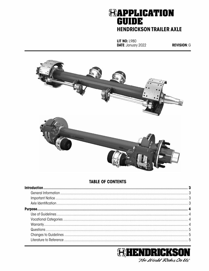
TABLE OF CONTENTSIntroduction ������������������������������������������������������������������������������������������������������������������������������������������ 3
General Information ������������������������������������������������������������������������������������������������������������������������������������ 3Important Notice ����������������������������������������������������������������������������������������������������������������������������������������� 3Axle Identification ���������������������������������������������������������������������������������������������������������������������������������������� 3
Purpose ������������������������������������������������������������������������������������������������������������������������������������������������ 4Use of Guidelines ���������������������������������������������������������������������������������������������������������������������������������������� 4Vocational Categories ��������������������������������������������������������������������������������������������������������������������������������� 4Warranty ����������������������������������������������������������������������������������������������������������������������������������������������������� 4Questions ��������������������������������������������������������������������������������������������������������������������������������������������������� 5Changes to Guidelines �������������������������������������������������������������������������������������������������������������������������������� 5Literature to Reference �������������������������������������������������������������������������������������������������������������������������������� 5
ApplicAtion GuideHENdrICkSON TrAILEr AxLE LIT NO: L980 dATE: January 2022 rEVISION: G
Value-Added Options ����������������������������������������������������������������������������������������������������������������������������� 5Wheel-end Offerings ����������������������������������������������������������������������������������������������������������������������������������� 5TIREMAAX® Tire Inflation Systems ����������������������������������������������������������������������������������������������������������������� 5Tire Inflation Prep ���������������������������������������������������������������������������������������������������������������������������������������� 5Cam Tubes ������������������������������������������������������������������������������������������������������������������������������������������������� 5HXS® Hendrickson Extended Service™ Brakes ���������������������������������������������������������������������������������������������� 6Anti-Lock Brake Systems (ABS) ��������������������������������������������������������������������������������������������������������������������� 6Brake Coating ��������������������������������������������������������������������������������������������������������������������������������������������� 6Air Disc Brake (ADB) Offerings ���������������������������������������������������������������������������������������������������������������������� 6
Gross Axle Weight rating (GAWr) and Axle Beam rating ����������������������������������������������������������������������� 6Gross Axle Weight Rating ����������������������������������������������������������������������������������������������������������������������������� 6Axle Beam Capacity ������������������������������������������������������������������������������������������������������������������������������������� 6Axle Beam Rating ���������������������������������������������������������������������������������������������������������������������������������������� 6Dimensional Requirements for Axle Beam Rating ������������������������������������������������������������������������������������������ 6
Axle Beam Capacities ��������������������������������������������������������������������������������������������������������������������������� 7Wall Thickness �������������������������������������������������������������������������������������������������������������������������������������������� 8Axle Track ��������������������������������������������������������������������������������������������������������������������������������������������������� 8
Axle Beam rating – Single Offset Wheels ���������������������������������������������������������������������������������������������� 9Axle Beam rating – Straight Axles ������������������������������������������������������������������������������������������������������� 10
Nominal Beam Ratings ������������������������������������������������������������������������������������������������������������������������������ 10
Mechanical Spring Suspensions ���������������������������������������������������������������������������������������������������������� 10Air Suspensions ���������������������������������������������������������������������������������������������������������������������������������� 11Air Suspension diagram ���������������������������������������������������������������������������������������������������������������������� 12Hendrickson Trailer Axle Beam ratings ������������������������������������������������������������������������������������������������ 13
Axle Beam Rating �������������������������������������������������������������������������������������������������������������������������������������� 13Axle Beam Rating - Drop Center and Raised Center Axle ������������������������������������������������������������������������������ 14
Brake Applications ������������������������������������������������������������������������������������������������������������������������������ 15Service Brake Requirements ���������������������������������������������������������������������������������������������������������������������� 15Brake Type ������������������������������������������������������������������������������������������������������������������������������������������������ 15
drum Brake Configurations ������������������������������������������������������������������������������������������������������������������ 16Cam Same vs� Cam Opposite �������������������������������������������������������������������������������������������������������������� 17Axle Structural rating vs� Brake Performance rating ���������������������������������������������������������������������������� 18S-cam drum Brake ratings ������������������������������������������������������������������������������������������������������������������ 19Brake Chamber Brackets and Slack Adjuster Clearance ������������������������������������������������������������������������� 20AdB Mounting requirements ��������������������������������������������������������������������������������������������������������������� 21
Caliper Rotation ���������������������������������������������������������������������������������������������������������������������������������������� 21Clearance Requirements ��������������������������������������������������������������������������������������������������������������������������� 22Caliper and Brake Chamber Travel ������������������������������������������������������������������������������������������������������������� 22Clocking Angle ������������������������������������������������������������������������������������������������������������������������������������������ 23Tire Inflation Installation ���������������������������������������������������������������������������������������������������������������������������� 24
2L980 G
ApplicAtion Guide — Hendrickson trAiler Axle
introductionHendrickson presents this publication to aid in understanding the Hendrickson Trailer Axle product offering and application requirements� Hendrickson Trailer Axles are engineered to meet the demanding requirements of the industry and incorporate the latest design and manufacturing technologies� These products are built specifically to provide a durable trailer axle to the market�
This document is to provide information to correctly align and mount a Hendrickson TRLAXLE loose axle equipped with drum or air disc brakes (ADB) prior to attachment to a suspension� Hendrickson literature number L577 HT™ Series Suspension Installation Procedures is the primary document for assembling a loose axle to Hendrickson’s HT Series suspensions�
GenerAl inForMAtionThe descriptions and specifications contained in this publication are current at the time of printing�
Hendrickson reserves the right to discontinue or modify its models and / or procedures and to change specifications at any time without notice�
Any reference to brand names in this publication are made as an example of the types of tools and materials recommended for use and should not be considered an endorsement� Equivalents may be used�
iMportAnt noticeHazard signal words (such as Warning or Caution) appear in various locations throughout this and other Hendrickson publications� Information accented by one of these signal words must be observed at all times� Refer to Hendrickson literature number t12007 Technical Procedure General Safety Precautions and Information for more details�
note: Additional service information not covered in the service procedures�
Welding or machining on any axle component is prohibited unless noted otherwise in this document or other Hendrickson service literature�
Fixed (mechanical) axle stops are prohibited to contact the axle and limit travel�
Swing arm mechanisms are approved in some loading and unloading applications� Contact Hendrickson for assistance�
Axle identiFicAtionStandard Hendrickson trailer axles are available in various spindle and tube combinations and are designed for on-highway use� Axles can be ordered fully dressed with hubs and brake drums or with air disc brakes� Other miscellaneous components such as slack adjusters, air chambers, cam tubes, etc� can also be specified�
3L980 G
ApplicAtion Guide — Hendrickson trAiler Axle
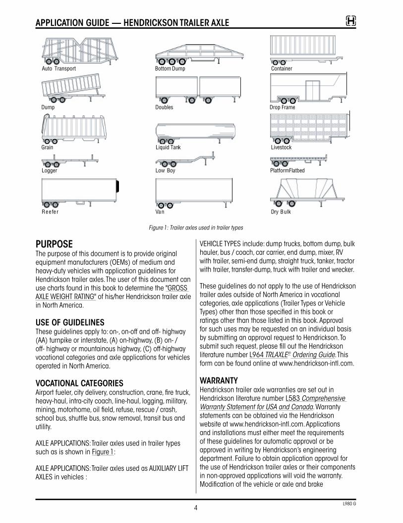
Figure 1: Trailer axles used in trailer types
purposeThe purpose of this document is to provide original equipment manufacturers (OEMs) of medium and heavy-duty vehicles with application guidelines for Hendrickson trailer axles� The user of this document can use charts found in this book to determine the "GROSS AXLE WEIGHT RATING" of his/her Hendrickson trailer axle in North America�
use oF GuidelinesThese guidelines apply to: on-, on-off and off- highway (AA) turnpike or interstate, (A) on-highway, (B) on- / off- highway or mountainous highway, (C) off-highway vocational categories and axle applications for vehicles operated in North America�
VocAtionAl cAteGoriesAirport fueler, city delivery, construction, crane, fire truck, heavy-haul, intra-city coach, line-haul, logging, military, mining, motorhome, oil field, refuse, rescue / crash, school bus, shuttle bus, snow removal, transit bus and utility�
AXLE APPLICATIONS: Trailer axles used in trailer types such as is shown in Figure 1:
AXLE APPLICATIONS: Trailer axles used as AUXILIARY LIFT AXLES in vehicles :
VEHICLE TYPES include: dump trucks, bottom dump, bulk hauler, bus / coach, car carrier, end dump, mixer, RV with trailer, semi-end dump, straight truck, tanker, tractor with trailer, transfer-dump, truck with trailer and wrecker�
These guidelines do not apply to the use of Hendrickson trailer axles outside of North America in vocational categories, axle applications (Trailer Types or Vehicle Types) other than those specified in this book or ratings other than those listed in this book� Approval for such uses may be requested on an individual basis by submitting an approval request to Hendrickson� To submit such request, please fill out the Hendrickson literature number L964 TRLAXLE® Ordering Guide� This form can be found online at www�hendrickson-intl�com�
WArrAntYHendrickson trailer axle warranties are set out in Hendrickson literature number L583 Comprehensive Warranty Statement for USA and Canada� Warranty statements can be obtained via the Hendrickson website at www�hendrickson-intl�com� Applications and installations must either meet the requirements of these guidelines for automatic approval or be approved in writing by Hendrickson’s engineering department� Failure to obtain application approval for the use of Hendrickson trailer axles or their components in non-approved applications will void the warranty� Modification of the vehicle or axle and brake
4L980 G
ApplicAtion Guide — Hendrickson trAiler Axle
configuration, changes in the vocational use or service outside the limits of these guidelines may void warranty coverage�
QuestionsFor answers to questions concerning the guidelines or to request a Hendrickson trailer axle Spec Form for a use not covered by these guidelines, contact:
Hendrickson trailer technical services 2070 Industrial Place S�E� Canton, OH 44707-2641 Telephone: 866-743-3247 (866-RIDE-AIR) email: Htts@Hendrickson-intl�com Website: www�hendrickson-intl�com
cHAnGes to GuidelinesThese guidelines are subject to change at any time without prior notice at the discretion of Hendrickson� To get the most up-to-date version of these guidelines visit www�hendrickson-intl�com�
literAture to reFerenceHendrickson literature can be found online at
www�Hendrickson-intl�com/TrailerLit
LIT� # dESCrIPTIONL577 HT™ Series Suspension Installation ProcedureL583 Comprehensive Warranty StatementL809 Brake CertificationsL846 Wide Base Tire ConfigurationL961 TRLAXLE® FlyerL964 TRLAXLE Ordering GuideL977 Identification Guide – Trailer Suspension Systems
L1073 Hendrickson Fixed Suspension Information and Requirements
L1200 RTR® Ready-to-Roll® FlyerL1225 Air Disc Brake Application Guide
L1239 Hendrickson MAXX22T™ Flyer
VAlue-Added optionsHendrickson Trailer Commercial Vehicle Systems works closely with fleets and trailer manufacturers to create products that offer versatility in application, added reliability and reduced costs� These value added options are enhanced features that are designed to reduce life cycle costs�
WHeel-end oFFerinGsHendrickson Trailer Commercial Vehicle Systems offers a variety of wheel-ends to fit your needs�
— HXL7® Hendrickson Extended-Life 7-year System™ uses semi-fluid grease and comes with a seven-year limited warranty 1
— HXL5® Hendrickson Extended-Life 5-year System™ uses semi-fluid grease and comes with a five-year limited warranty 1
— HXL3® Hendrickson Extended-Life 3-year System™ uses an oil bath method and comes with a three-year limited warranty 1
— Hendrickson also offers a ConMet PreSet hub
tireMAAx® tire inFlAtion sYsteMsHendrickson offers two TIREMAAX® tire inflation systems to suit your tire inflation needs�
TIREMAAX PRO – Constantly monitors and adjusts tire pressure
TIREMAAX CP – Constant pressure controlled by regulator
tire inFlAtion prepHendrickson trailer axles can be prepped for use with tire inflation systems� Axle spindles come without plugs installed and axles are pre-drilled to accept the hardware and fittings of various systems offered� Please check with your Customer Service Representative for available system preps�
cAM tuBesCam tubes cover the brake camshaft from the brake spider to the cam support bracket and are filled with grease� Cam tubes often extend the life of seals and bushings used on trailer axle brake spiders and cam brackets as well as reduce vibration in the axle� Cam tubes are particularly popular in the Northern United States and Canada where they are used to help keep road salts and other chemicals from contaminating the bushings and seals�
1 Contact your local Hendrickson representative for complete warranty terms, conditions and limitations�
5L980 G
ApplicAtion Guide — Hendrickson trAiler Axle
Hxs® Hendrickson extended serVice™ BrAkesHXS® Hendrickson Extended Service™ brakes extend intervals between brake service�
Anti-lock BrAke sYsteMs (ABs)Since January 1998, the U�S� Government has mandated anti-lock brake systems on new semi-trailers� Hendrickson offers trailer axles with ABS mounting brackets, ABS tone ring hubs and ABS sensors�
BrAke coAtinGE-coat – All Hendrickson brake shoes utilize a high quality e-coat process for improved resistance to rust-jacking
AAXTREME COAT® – Premium brake shoe coatings available and provide extreme corrosion protection in the toughest environments
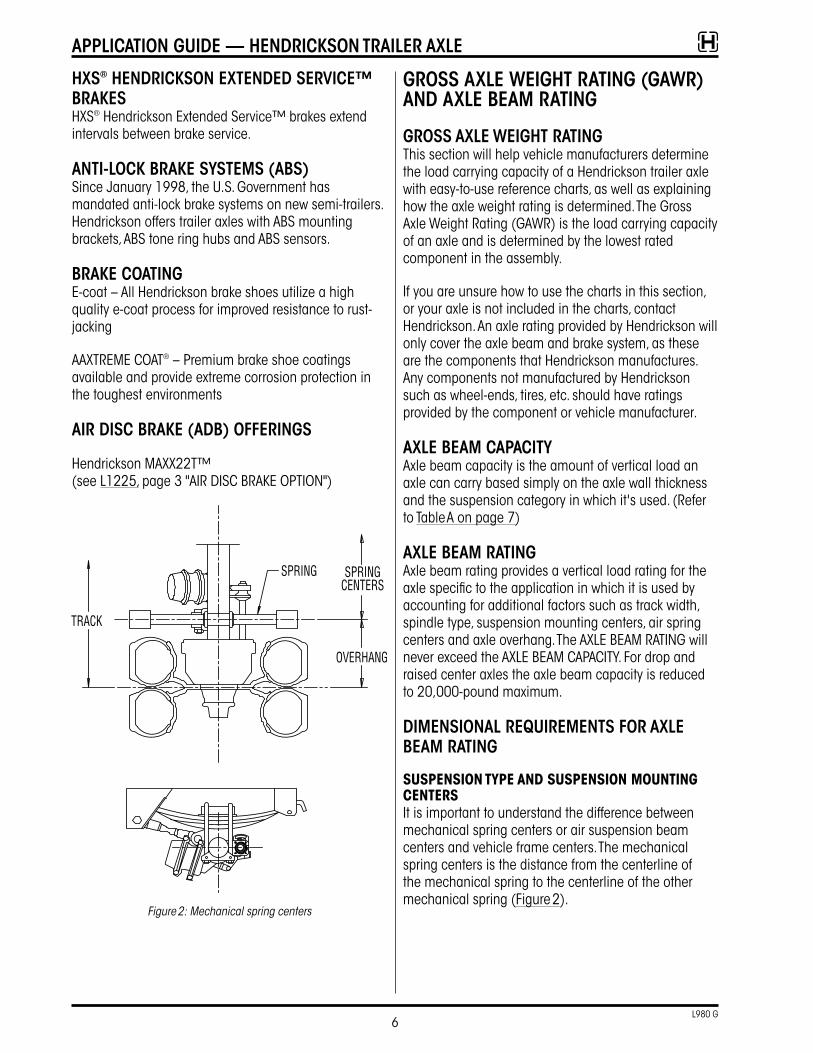
Air disc BrAke (AdB) oFFerinGs
Hendrickson MAXX22T™ (see L1225, page 3 "AIR DISC BRAKE OPTION")
Figure 2: Mechanical spring centers
Gross Axle WeiGHt rAtinG (GAWr) And Axle BeAM rAtinG
Gross Axle WeiGHt rAtinGThis section will help vehicle manufacturers determine the load carrying capacity of a Hendrickson trailer axle with easy-to-use reference charts, as well as explaining how the axle weight rating is determined� The Gross Axle Weight Rating (GAWR) is the load carrying capacity of an axle and is determined by the lowest rated component in the assembly�
If you are unsure how to use the charts in this section, or your axle is not included in the charts, contact Hendrickson� An axle rating provided by Hendrickson will only cover the axle beam and brake system, as these are the components that Hendrickson manufactures� Any components not manufactured by Hendrickson such as wheel-ends, tires, etc� should have ratings provided by the component or vehicle manufacturer�
Axle BeAM cApAcitYAxle beam capacity is the amount of vertical load an axle can carry based simply on the axle wall thickness and the suspension category in which it's used� (Refer to Table A on page 7)
Axle BeAM rAtinGAxle beam rating provides a vertical load rating for the axle specific to the application in which it is used by accounting for additional factors such as track width, spindle type, suspension mounting centers, air spring centers and axle overhang� The AXLE BEAM RATING will never exceed the AXLE BEAM CAPACITY� For drop and raised center axles the axle beam capacity is reduced to 20,000-pound maximum�
diMensionAl reQuireMents For Axle BeAM rAtinG
SUSPENSION TYPE ANd SUSPENSION MOUNTING CENTErSIt is important to understand the difference between mechanical spring centers or air suspension beam centers and vehicle frame centers� The mechanical spring centers is the distance from the centerline of the mechanical spring to the centerline of the other mechanical spring (Figure 2)�
6L980 G
ApplicAtion Guide — Hendrickson trAiler Axle

Axle BeAM cApAcities
spindle tYpe HN HP
spindle GrApHic
recoMMendedAxle use On / Off Highway On / Off Highway
ApplicAtion Dry Van, Reefers,Vocational (Flats, Dumps, Autohaulers, Tanks, Lowboys)
Dry Van, Reefers,Vocational (Flats, Dumps, Autohaulers, Tanks, Lowboys), super singles w/
offset wheels
suspension Mechanical Spring Air Ride Mechanical Spring Air Ride
Axle diAMeter 5" round 5" round 5" round 5" round
AXLE
BEA
M C
APAC
ITIE
S IN
PO
UNDS
(u
nles
s ot
herw
ise
note
d)
1/2" noM. WAll Up to 22,500 Not allowed Up to 22,500 Not allowed
5/8" noM. WAll Up to 25,000 Up to 22,500 Up to 25,000 Up to 22,500
5/8" Hd WAll Up to 25,400 Up to 23,000 Up to 25,400 Up to 23,000
3/4" WAll Up to 27,000 Up to 25,000 Up to 27,000 Up to 25,000
solid BAr N/A N/A N/A N/A
drop Axle Up to 20,000 Up to 20,000 Up to 20,000 Up to 20,000
Table A
7L980 G
ApplicAtion Guide — Hendrickson trAiler Axle
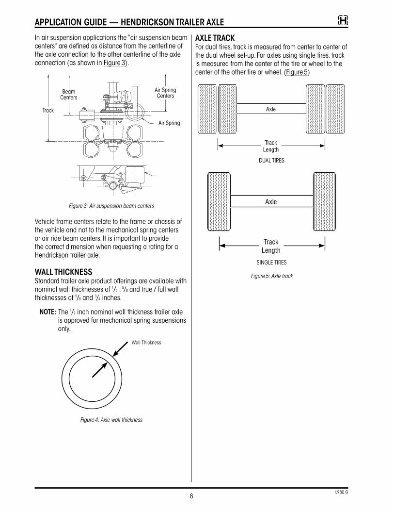
In air suspension applications the “air suspension beam centers” are defined as distance from the centerline of the axle connection to the other centerline of the axle connection (as shown in Figure 3)�
Track
Beam Centers
Air Spring Centers
Air Spring
Figure 3: Air suspension beam centers
Vehicle frame centers relate to the frame or chassis of the vehicle and not to the mechanical spring centers or air ride beam centers� It is important to provide the correct dimension when requesting a rating for a Hendrickson trailer axle�
WAll tHicknessStandard trailer axle product offerings are available with nominal wall thicknesses of 1/2 , 5/8 and true / full wall thicknesses of 5/8 and 3/4 inches�
note: The 1/2 inch nominal wall thickness trailer axle is approved for mechanical spring suspensions only�
Wall Thickness
Figure 4: Axle wall thickness
Axle trAckFor dual tires, track is measured from center to center of the dual wheel set-up� For axles using single tires, track is measured from the center of the tire or wheel to the center of the other tire or wheel� (Figure 5)
DUAL TIRES
SINGLE TIRES
Figure 5: Axle track
8L980 G
ApplicAtion Guide — Hendrickson trAiler Axle
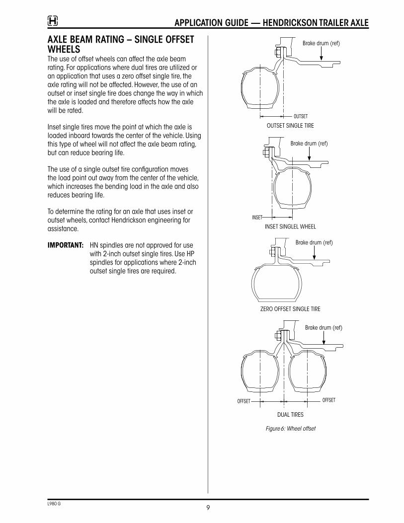
Axle BeAM rAtinG – sinGle oFFset WHeelsThe use of offset wheels can affect the axle beam rating� For applications where dual tires are utilized or an application that uses a zero offset single tire, the axle rating will not be affected� However, the use of an outset or inset single tire does change the way in which the axle is loaded and therefore affects how the axle will be rated�
Inset single tires move the point at which the axle is loaded inboard towards the center of the vehicle� Using this type of wheel will not affect the axle beam rating, but can reduce bearing life�
The use of a single outset tire configuration moves the load point out away from the center of the vehicle, which increases the bending load in the axle and also reduces bearing life�
To determine the rating for an axle that uses inset or outset wheels, contact Hendrickson engineering for assistance�
IMPOrTANT: HN spindles are not approved for use with 2-inch outset single tires� Use HP spindles for applications where 2-inch outset single tires are required�
OUTSET SINGLE TIRE
INSET SINGLEL WHEEL
ZERO OFFSET SINGLE TIRE
DUAL TIRES
Figure 6: Wheel offset
Brake drum (ref)
Brake drum (ref)
Brake drum (ref)
Brake drum (ref)
9L980 G
ApplicAtion Guide — Hendrickson trAiler Axle
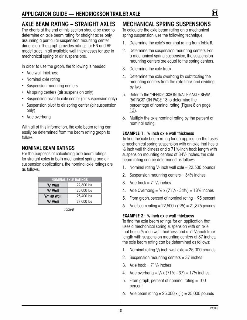
Axle BeAM rAtinG – strAiGHt AxlesThe charts at the end of this section should be used to determine an axle beam rating for straight axles only, assuming a particular suspension mounting center dimension� The graph provides ratings for HN and HP model axles in all available wall thicknesses for use in mechanical spring or air suspensions�
In order to use the graph, the following is needed:• Axle wall thickness• Nominal axle rating• Suspension mounting centers• Air spring centers (air suspension only)• Suspension pivot to axle center (air suspension only)• Suspension pivot to air spring center (air suspension
only)• Axle overhang
With all of this information, the axle beam rating can easily be determined from the beam rating graph to follow�
noMinAl BeAM rAtinGsFor the purposes of calculating axle beam ratings for straight axles in both mechanical spring and air suspension applications, the nominal axle ratings are as follows:
NOMINAL AxLE rATINGS1/2" Wall 22,500 lbs5/8" Wall 25,000 lbs
5/8" Hd Wall 25,400 lbs3/4" Wall 27,000 lbs
Table B
MecHAnicAl sprinG suspensionsTo calculate the axle beam rating on a mechanical spring suspension, use the following technique:
1� Determine the axle's nominal rating from Table B�
2� Determine the suspension mounting centers� For a mechanical spring suspension, the suspension mounting centers are equal to the spring centers�
3� Determine the axle track�
4� Determine the axle overhang by subtracting the mounting centers from the axle track and dividing by two�
5� Refer to the "HENDRICKSON TRAILER AXLE BEAM RATINGS" ON PAGE 13 to determine the percentage of nominal rating (Figure 8 on page 13)�
6� Multiply the axle nominal rating by the percent of nominal rating�
ExAMPLE 1: 1/2 inch axle wall thicknessTo find the axle beam rating for an application that uses a mechanical spring suspension with an axle that has a ½ inch wall thickness and a 711/2-inch track length with suspension mounting centers of 341/2 inches, the axle beam rating can be determined as follows:
1� Nominal rating 1/2 inch wall axle = 22,500 pounds
2� Suspension mounting centers = 34½ inches
3� Axle track = 711/2 inches
4� Axle Overhang = 1/2 x (711/2 - 34½) = 181/2 inches
5� From graph, percent of nominal rating = 95 percent
6� Axle beam rating = 22,500 x (�95) = 21,375 pounds
ExAMPLE 2: 5/8 inch axle wall thicknessTo find the axle beam ratings for an application that uses a mechanical spring suspension with an axle that has a 5/8 inch wall thickness and a 711/2-inch track length with suspension mounting centers of 37 inches, the axle beam rating can be determined as follows:
1� Nominal rating 5/8 inch wall axle = 25,000 pounds
2� Suspension mounting centers = 37 inches
3� Axle track = 711/2 inches
4� Axle overhang = 1/2 x (711/2 - 37) = 17¼ inches
5� From graph, percent of nominal rating = 100 percent
6� Axle beam rating = 25,000 x (1) = 25,000 pounds
10L980 G
ApplicAtion Guide — Hendrickson trAiler Axle
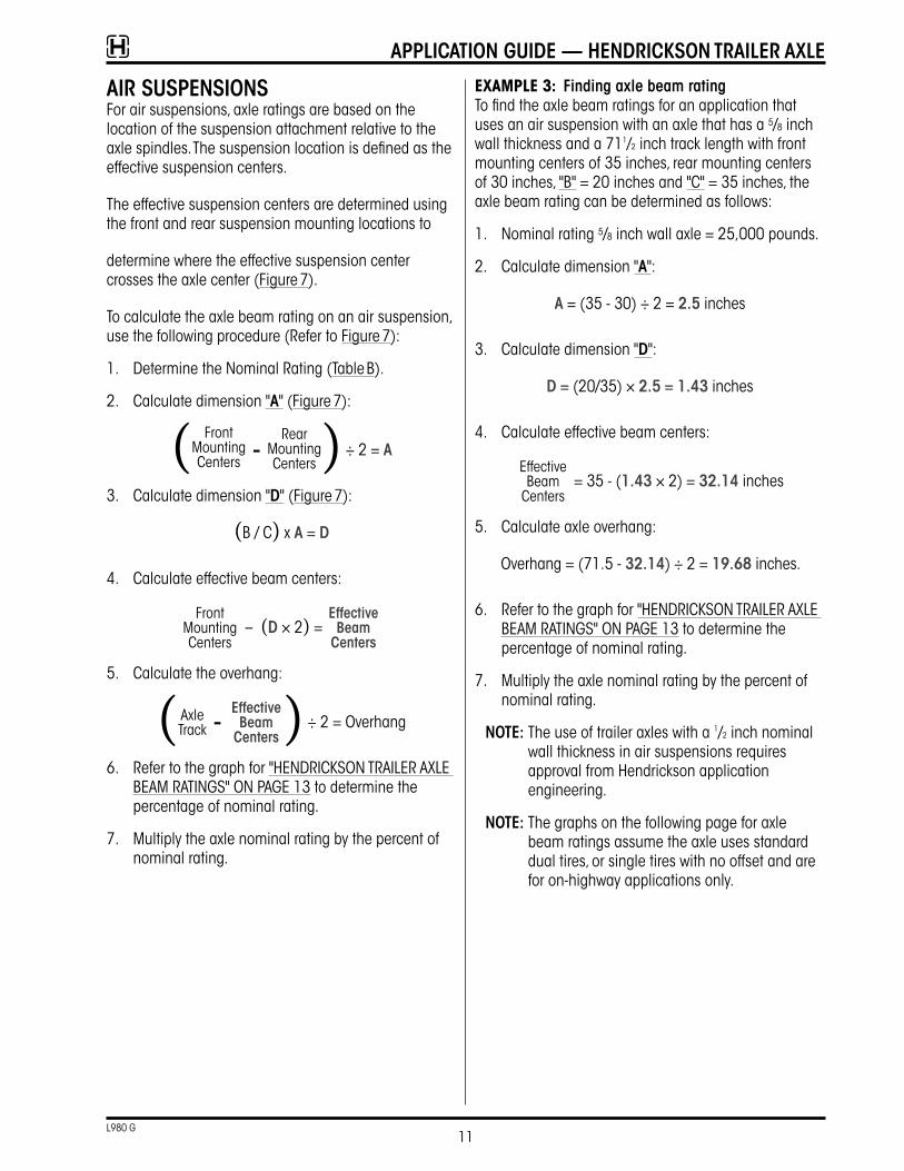
Air suspensionsFor air suspensions, axle ratings are based on the location of the suspension attachment relative to the axle spindles� The suspension location is defined as the effective suspension centers�
The effective suspension centers are determined using the front and rear suspension mounting locations to
determine where the effective suspension center crosses the axle center (Figure 7)�
To calculate the axle beam rating on an air suspension, use the following procedure (Refer to Figure 7):
1� Determine the Nominal Rating (Table B)�
2� Calculate dimension "A" (Figure 7):
( Front Mounting Centers
– Rear
Mounting Centers) ÷ 2 = A
3� Calculate dimension "d" (Figure 7):
(B / C) x A = d
4� Calculate effective beam centers:
Front Mounting Centers
– (d × 2) = effective
Beam centers
5� Calculate the overhang:
( Axle Track –
effective Beam
centers) ÷ 2 = Overhang
6� Refer to the graph for "HENDRICKSON TRAILER AXLE BEAM RATINGS" ON PAGE 13 to determine the percentage of nominal rating�
7� Multiply the axle nominal rating by the percent of nominal rating�
ExAMPLE 3: Finding axle beam ratingTo find the axle beam ratings for an application that uses an air suspension with an axle that has a 5/8 inch wall thickness and a 711/2 inch track length with front mounting centers of 35 inches, rear mounting centers of 30 inches, "B" = 20 inches and "C" = 35 inches, the axle beam rating can be determined as follows:
1� Nominal rating 5/8 inch wall axle = 25,000 pounds�
2� Calculate dimension "A":
A = (35 - 30) ÷ 2 = 2.5 inches
3� Calculate dimension "d":
d = (20/35) × 2.5 = 1.43 inches
4� Calculate effective beam centers:
Effective Beam
Centers = 35 - (1.43 × 2) = 32.14 inches
5� Calculate axle overhang:
Overhang = (71�5 - 32.14) ÷ 2 = 19.68 inches�
6� Refer to the graph for "HENDRICKSON TRAILER AXLE BEAM RATINGS" ON PAGE 13 to determine the percentage of nominal rating�
7� Multiply the axle nominal rating by the percent of nominal rating�
note: The use of trailer axles with a 1/2 inch nominal wall thickness in air suspensions requires approval from Hendrickson application engineering�
note: The graphs on the following page for axle beam ratings assume the axle uses standard dual tires, or single tires with no offset and are for on-highway applications only�
11L980 G
ApplicAtion Guide — Hendrickson trAiler Axle
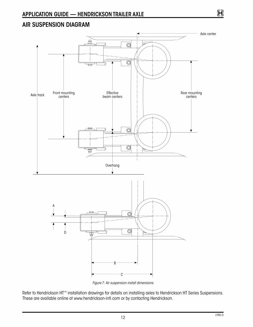
Air suspension diAGrAM
Rear mounting centers
Effective beam centers
Overhang
Front mounting centersAxle track
Axle center
Figure 7: Air suspension install dimensions
Refer to Hendrickson HT™ installation drawings for details on installing axles to Hendrickson HT Series Suspensions� These are available online at www�hendrickson-intl�com or by contacting Hendrickson�
A
D
B
C
12L980 G
ApplicAtion Guide — Hendrickson trAiler Axle
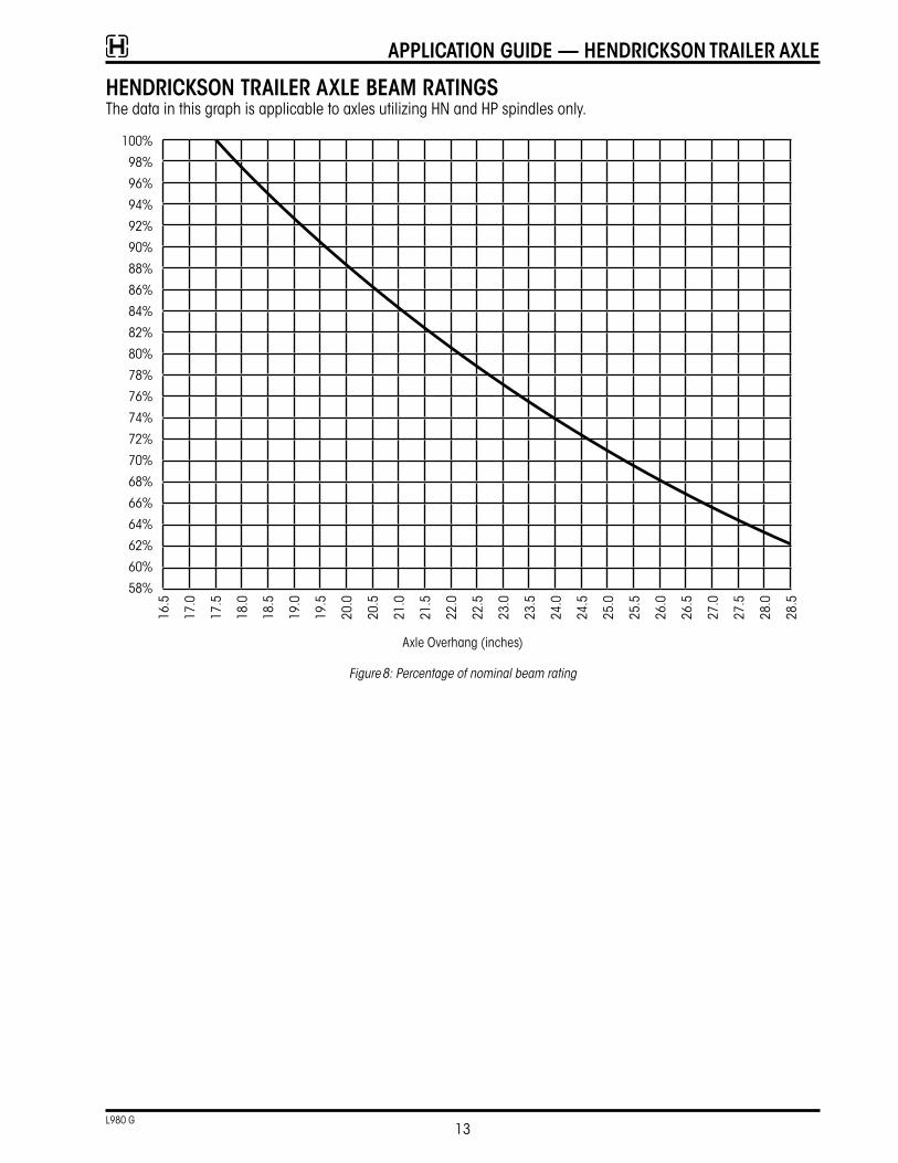
Hendrickson trAiler Axle BeAM rAtinGsThe data in this graph is applicable to axles utilizing HN and HP spindles only�
100%
98%
96%
94%
92%
90%
88%
86%
84%
82%
80%
78%
76%
74%
72%
70%
68%
66%
64%
62%
60%
58%
16�5
17�0
17�5
18�0
18�5
19�0
19�5
20�0
20�5
21�0
21�5
22�0
22�5
23�0
23�5
24�0
24�5
25�0
25�5
26�0
26�5
27�0
27�5
28�0
28�5
Axle Overhang (inches)
Figure 8: Percentage of nominal beam rating
13L980 G
ApplicAtion Guide — Hendrickson trAiler Axle
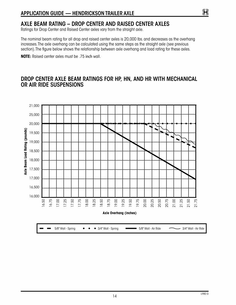
Axle BeAM rAtinG – drop center And rAised center AxlesRatings for Drop Center and Raised Center axles vary from the straight axle�
The nominal beam rating for all drop and raised center axles is 20,000 lbs� and decreases as the overhang increases� The axle overhang can be calculated using the same steps as the straight axle (see previous section)� The figure below shows the relationship between axle overhang and load rating for these axles�
NOTE: Raised center axles must be �75 inch wall�
Axle
Bea
m L
oad
ratin
g (p
ound
s)
Axle Overhang (inches)
5/8" Wall - Spring 3/4" Wall - Spring 5/8" Wall - Air Ride 3/4" Wall - Air Ride
drop center Axle BeAM rAtinGs For Hp, Hn, And Hr WitH MecHAnicAl or Air ride suspensions
21,000
25,000
20,000
19,500
19,000
18,500
18,000
17,500
17,000
16,500
16,000
16�5
0
16�7
5
17�0
0
17�2
5
17�5
0
17�7
5
18�0
0
18�2
5
18�5
0
18�7
5
19�0
0
19�2
5
19�5
0
19�7
5
20�0
0
20�2
5
20�5
0
20�7
5
21�0
0
21�2
5
21�5
0
21�7
5
14L980 G
ApplicAtion Guide — Hendrickson trAiler Axle
BrAke ApplicAtions
serVice BrAke reQuireMentsHendrickson offers a variety of sizes and models of brakes� Federal law requires all brakes/axles meet the performance standard set by FMVSS-121 regulations� FMVSS-121 is applicable to vehicles that travel more than 55 MPH and brakes that are rated less than 29,000 pounds�
Canadian law requires brakes to meet CMVSS-121� CMVSS-121 requires that all brakes meet a draw bar requirement� If a trailer brake assembly will be used in Canada it must meet Canadian draw bar certification requirements�
The original equipment manufacturer (OEM) has the responsibility of ensuring that its trailers meet the certification requirements� For additional information regarding brake certifications contact Hendrickson engineering�
The following section is to be used to aid in the selection of the appropriate brake for the application� Each brake approval shown is based on GAWR (page 6), static loaded radius (SLR), air chamber size, brake adjuster length (drum brake only) and the brake lining material�
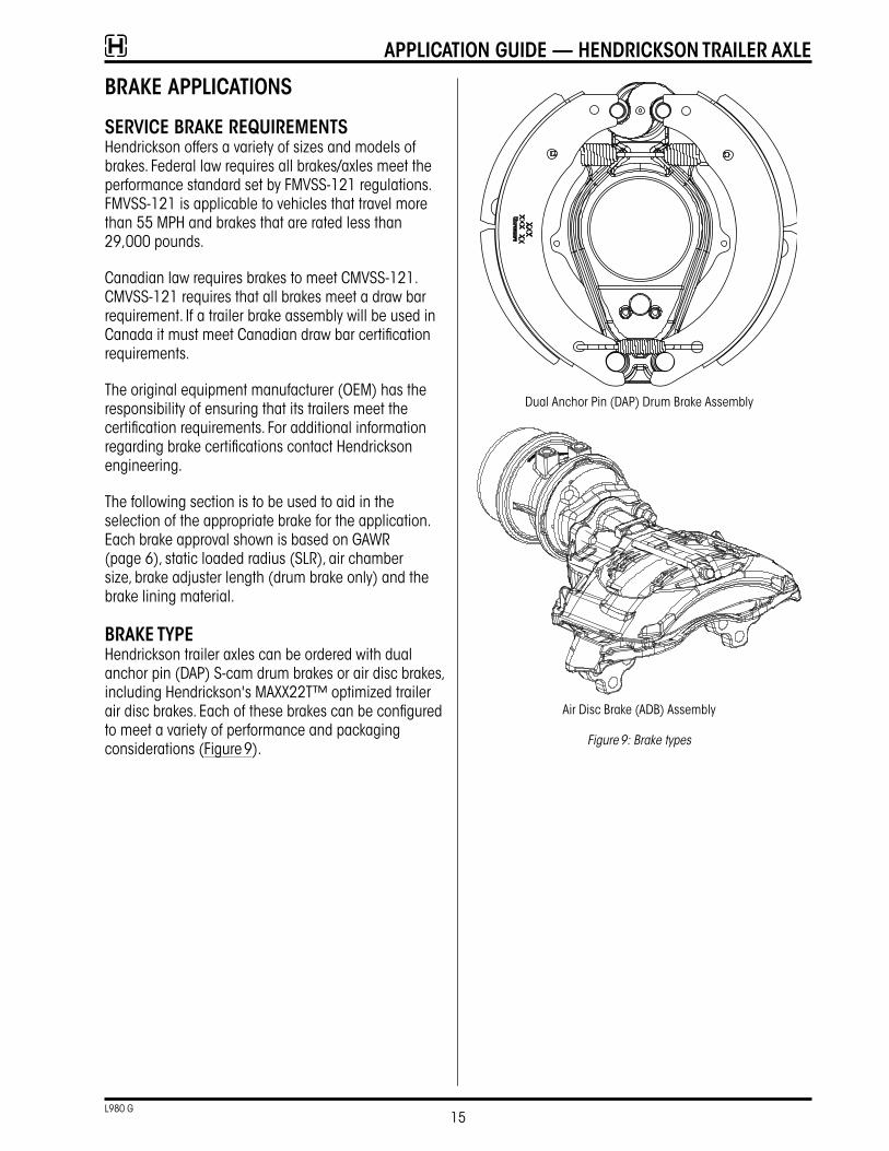
BrAke tYpeHendrickson trailer axles can be ordered with dual anchor pin (DAP) S-cam drum brakes or air disc brakes, including Hendrickson's MAXX22T™ optimized trailer air disc brakes� Each of these brakes can be configured to meet a variety of performance and packaging considerations (Figure 9)�
Dual Anchor Pin (DAP) Drum Brake Assembly
Air Disc Brake (ADB) Assembly
Figure 9: Brake types
15L980 G
ApplicAtion Guide — Hendrickson trAiler Axle
ApplicAtion Guide — Hendrickson trAiler Axle
16L980 Rev G
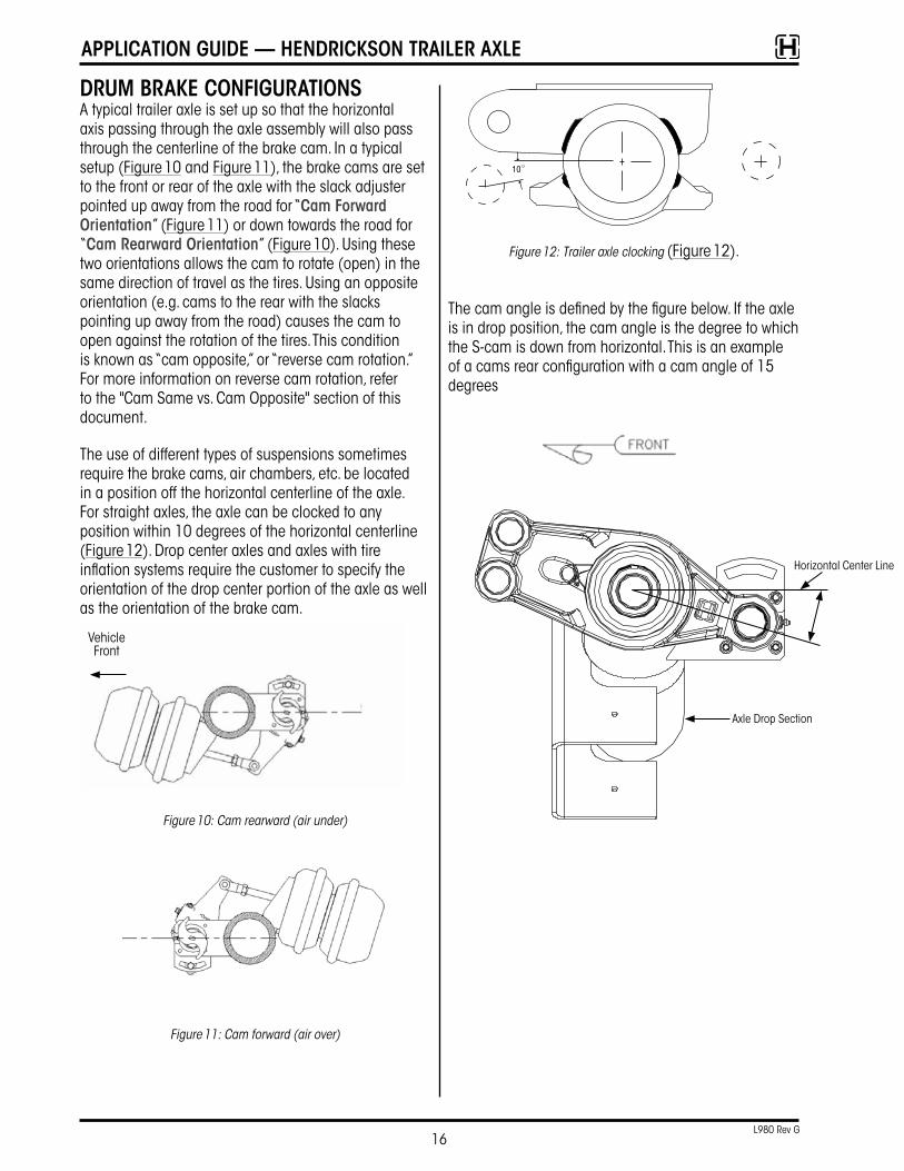
druM BrAke conFiGurAtionsA typical trailer axle is set up so that the horizontal axis passing through the axle assembly will also pass through the centerline of the brake cam� In a typical setup (Figure 10 and Figure 11), the brake cams are set to the front or rear of the axle with the slack adjuster pointed up away from the road for “cam Forward orientation” (Figure 11) or down towards the road for “cam rearward orientation” (Figure 10)� Using these two orientations allows the cam to rotate (open) in the same direction of travel as the tires� Using an opposite orientation (e�g� cams to the rear with the slacks pointing up away from the road) causes the cam to open against the rotation of the tires� This condition is known as “cam opposite,” or “reverse cam rotation�” For more information on reverse cam rotation, refer to the "Cam Same vs� Cam Opposite" section of this document�
The use of different types of suspensions sometimes require the brake cams, air chambers, etc� be located in a position off the horizontal centerline of the axle� For straight axles, the axle can be clocked to any position within 10 degrees of the horizontal centerline (Figure 12)� Drop center axles and axles with tire inflation systems require the customer to specify the orientation of the drop center portion of the axle as well as the orientation of the brake cam�
Figure 10: Cam rearward (air under)
Figure 11: Cam forward (air over)
10
Figure 12: Trailer axle clocking (Figure 12)�
The cam angle is defined by the figure below� If the axle is in drop position, the cam angle is the degree to which the S-cam is down from horizontal� This is an example of a cams rear configuration with a cam angle of 15 degrees
Vehicle Front
Axle Drop Section
Horizontal Center Line
ApplicAtion Guide — Hendrickson trAiler Axle
17L980 Rev G
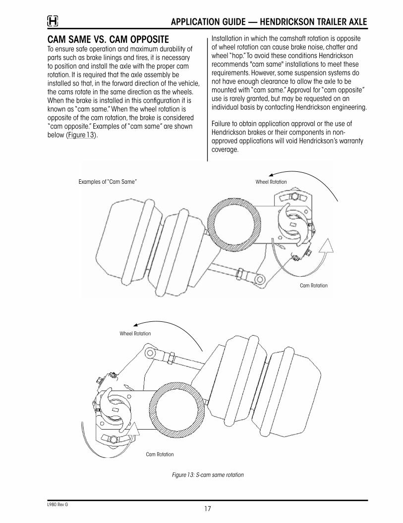
cAM sAMe Vs. cAM oppositeTo ensure safe operation and maximum durability of parts such as brake linings and tires, it is necessary to position and install the axle with the proper cam rotation� It is required that the axle assembly be installed so that, in the forward direction of the vehicle, the cams rotate in the same direction as the wheels� When the brake is installed in this configuration it is known as “cam same�” When the wheel rotation is opposite of the cam rotation, the brake is considered “cam opposite�” Examples of “cam same” are shown below (Figure 13)�
Installation in which the camshaft rotation is opposite of wheel rotation can cause brake noise, chatter and wheel “hop�” To avoid these conditions Hendrickson recommends "cam same" installations to meet these requirements� However, some suspension systems do not have enough clearance to allow the axle to be mounted with “cam same�” Approval for “cam opposite” use is rarely granted, but may be requested on an individual basis by contacting Hendrickson engineering�
Failure to obtain application approval or the use of Hendrickson brakes or their components in non-approved applications will void Hendrickson’s warranty coverage�
Cam Rotation
Cam Rotation
Wheel Rotation
Wheel Rotation
Examples of “Cam Same”
Figure 13: S-cam same rotation
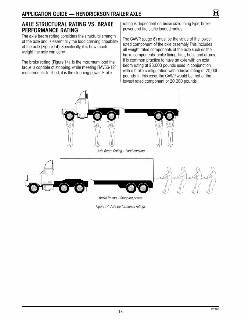
Axle structurAl rAtinG Vs. BrAke perForMAnce rAtinGThe axle beam rating considers the structural strength of the axle and is essentially the load carrying capability of the axle (Figure 14)� Specifically, it is how much weight the axle can carry�
The brake rating (Figure 14)� is the maximum load the brake is capable of stopping, while meeting FMVSS-121 requirements� In short, it is the stopping power� Brake
rating is dependent on brake size, lining type, brake power and tire static loaded radius�
The GAWR (page 6) must be the value of the lowest rated component of the axle assembly� This includes all weight rated components of the axle such as the brake components, brake lining, tires, hubs and drums� It is common practice to have an axle with an axle beam rating at 23,000 pounds used in conjunction with a brake configuration with a brake rating at 20,000 pounds� In this case, the GAWR would be that of the lowest rated component or 20,000 pounds�
Axle Beam Rating – Load carrying
Brake Rating – Stopping power
Figure 14: Axle performance ratings
18L980 G
ApplicAtion Guide — Hendrickson trAiler Axle
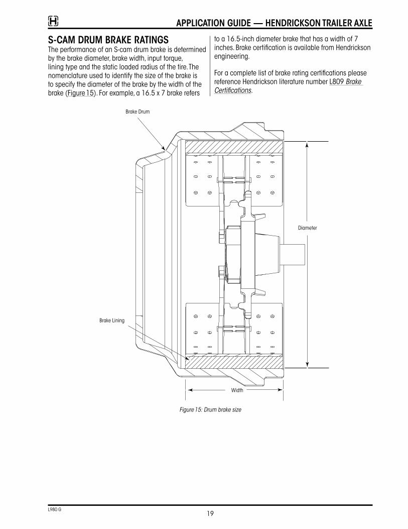
s-cAM druM BrAke rAtinGsThe performance of an S-cam drum brake is determined by the brake diameter, brake width, input torque, lining type and the static loaded radius of the tire� The nomenclature used to identify the size of the brake is to specify the diameter of the brake by the width of the brake (Figure 15)� For example, a 16�5 x 7 brake refers
to a 16�5-inch diameter brake that has a width of 7 inches� Brake certification is available from Hendrickson engineering�
For a complete list of brake rating certifications please reference Hendrickson literature number L809 Brake Certifications�
Figure 15: Drum brake size
Brake Drum
Brake Lining
Width
Diameter
19L980 G
ApplicAtion Guide — Hendrickson trAiler Axle
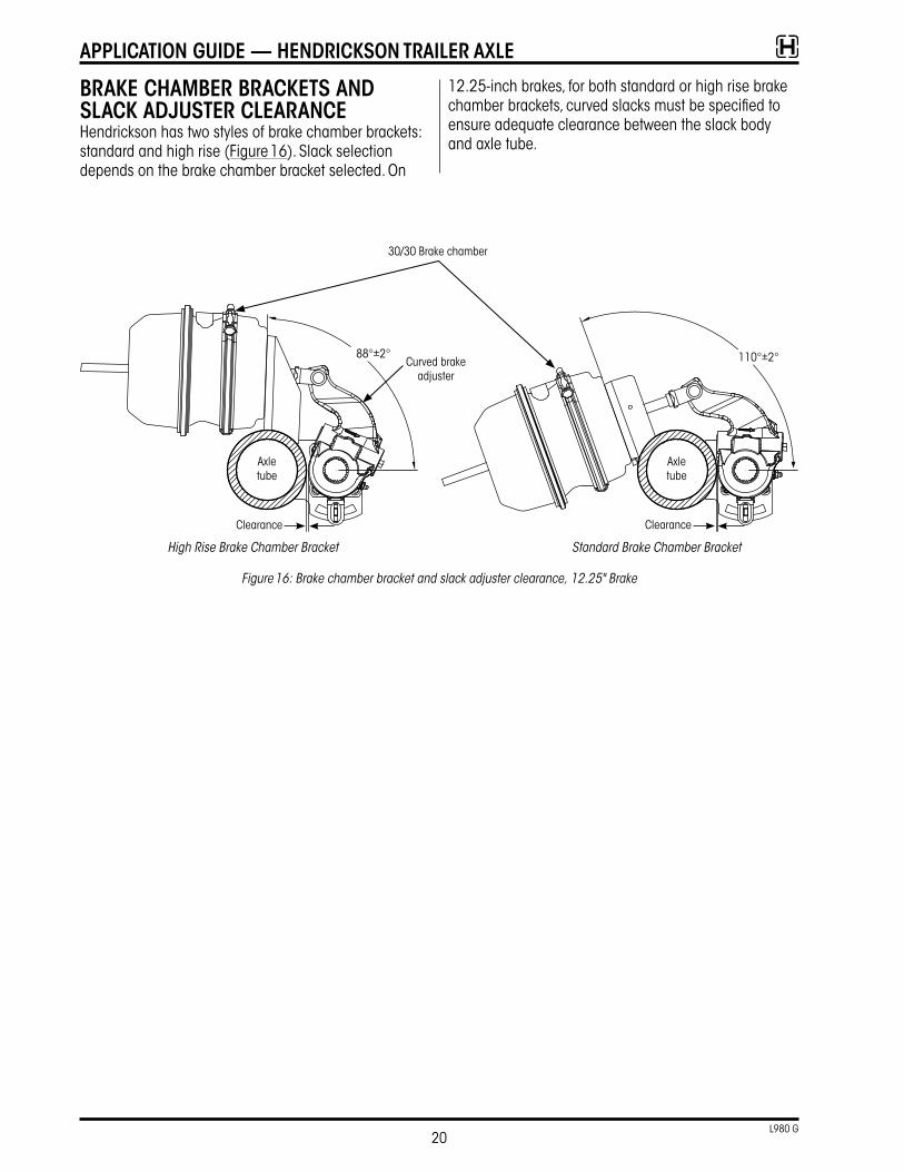
BrAke cHAMBer BrAckets And slAck AdJuster cleArAnceHendrickson has two styles of brake chamber brackets: standard and high rise (Figure 16)� Slack selection depends on the brake chamber bracket selected� On
12�25-inch brakes, for both standard or high rise brake chamber brackets, curved slacks must be specified to ensure adequate clearance between the slack body and axle tube�
High Rise Brake Chamber Bracket Standard Brake Chamber Bracket
Figure 16: Brake chamber bracket and slack adjuster clearance, 12.25" Brake
Axle tube
88°±2° 110°±2°
Axle tube
30/30 Brake chamber
Curved brake adjuster
Clearance Clearance
20L980 G
ApplicAtion Guide — Hendrickson trAiler Axle
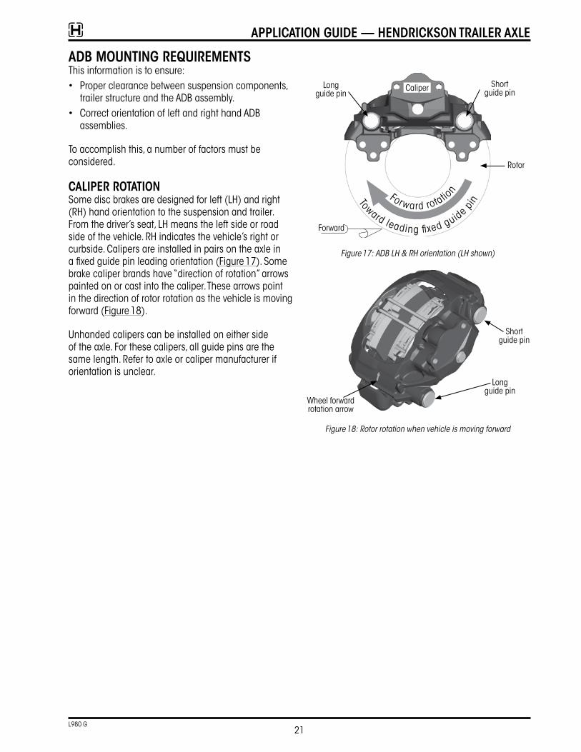
AdB MountinG reQuireMentsThis information is to ensure:• Proper clearance between suspension components,
trailer structure and the ADB assembly�• Correct orientation of left and right hand ADB
assemblies�
To accomplish this, a number of factors must be considered�
cAliper rotAtionSome disc brakes are designed for left (LH) and right (RH) hand orientation to the suspension and trailer� From the driver’s seat, LH means the left side or road side of the vehicle� RH indicates the vehicle’s right or curbside� Calipers are installed in pairs on the axle in a fixed guide pin leading orientation (Figure 17)� Some brake caliper brands have “direction of rotation” arrows painted on or cast into the caliper� These arrows point in the direction of rotor rotation as the vehicle is moving forward (Figure 18)�
Unhanded calipers can be installed on either side of the axle� For these calipers, all guide pins are the same length� Refer to axle or caliper manufacturer if orientation is unclear�
Caliper
Forward rotatio
n
Toward leading fi xed guide pin
Forward
Long guide pin
Short guide pin
Rotor
Figure 17: ADB LH & RH orientation (LH shown)
Long guide pin
Short guide pin
Wheel forward rotation arrow
Figure 18: Rotor rotation when vehicle is moving forward
21L980 G
ApplicAtion Guide — Hendrickson trAiler Axle
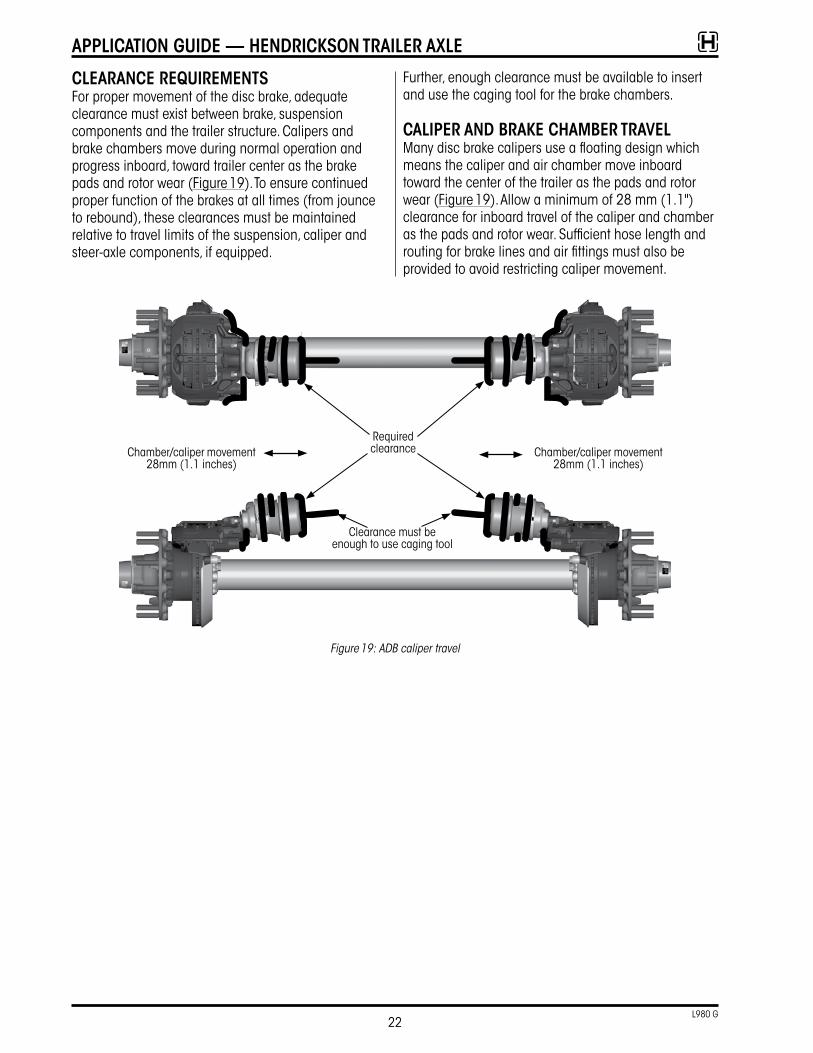
cleArAnce reQuireMentsFor proper movement of the disc brake, adequate clearance must exist between brake, suspension components and the trailer structure� Calipers and brake chambers move during normal operation and progress inboard, toward trailer center as the brake pads and rotor wear (Figure 19)� To ensure continued proper function of the brakes at all times (from jounce to rebound), these clearances must be maintained relative to travel limits of the suspension, caliper and steer-axle components, if equipped�
Further, enough clearance must be available to insert and use the caging tool for the brake chambers�
cAliper And BrAke cHAMBer trAVelMany disc brake calipers use a floating design which means the caliper and air chamber move inboard toward the center of the trailer as the pads and rotor wear (Figure 19)� Allow a minimum of 28 mm (1�1") clearance for inboard travel of the caliper and chamber as the pads and rotor wear� Sufficient hose length and routing for brake lines and air fittings must also be provided to avoid restricting caliper movement�
Chamber/caliper movement 28mm (1�1 inches)
Chamber/caliper movement 28mm (1�1 inches)
Required clearance
Clearance must be enough to use caging tool
Figure 19: ADB caliper travel
22L980 G
ApplicAtion Guide — Hendrickson trAiler Axle
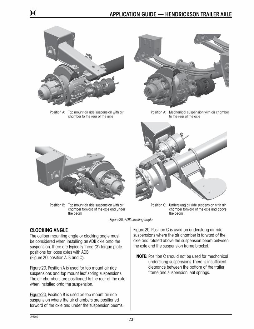
Position A: Top mount air ride suspension with air chamber to the rear of the axle
Position A: Mechanical suspension with air chamber to the rear of the axle
Position B: Top mount air ride suspension with air chamber forward of the axle and under the beam
Position C: Underslung air ride suspension with air chamber forward of the axle and above the beam
Figure 20: ADB clocking angle
clockinG AnGleThe caliper mounting angle or clocking angle must be considered when installing an ADB axle onto the suspension� There are typically three (3) torque plate positions for loose axles with ADB (Figure 20, position A, B and C)�
Figure 20, Position A is used for top mount air ride suspensions and top mount leaf spring suspensions� The air chambers are positioned to the rear of the axle when installed onto the suspension�
Figure 20, Position B is used on top mount air ride suspension where the air chambers are positioned forward of the axle and under the suspension beams�
Figure 20, Position C is used on underslung air ride suspensions where the air chamber is forward of the axle and rotated above the suspension beam between the axle and the suspension frame bracket�
NOTE: Position C should not be used for mechanical underslung suspensions� There is insufficient clearance between the bottom of the trailer frame and suspension leaf springs�
23L980 G
ApplicAtion Guide — Hendrickson trAiler Axle
tire inFlAtion instAllAtionTire inflation holes must always be on top of the axle when installed into suspensions� Refer to T51002 TIREMAAX® PRO and CP Installation and Maintenance Procedures.
For assistance in the United States and Canada, call Hendrickson trailer technical services at 866-RIDEAIR (743-3247) or email Htts@Hendrickson-intl�com�
ApplicAtion Guide — Hendrickson trAiler Axle
TRAILER COMMERCIAL VEHICLE SYSTEMS2070 Industrial Place SECanton, OH 44707-2641 USA866.RIDEAIR (743.3247) 330.489.0045 • Fax 800.696.4416
Hendrickson Canada ULC2825 Argentia Road, Unit #2 - 4Mississauga, ON Canada L5N 8G6800.668.5360905.789.1030 • Fax 905.802.9423
Hendrickson MexicanaCircuito El Marqués Sur #29Parque Industrial El MarquésPob. El Colorado, Municipio El Marqués, Querétaro, México C.P. 76246+52 (442) 296.3600 • Fax +52 (442) 296.3601
Call Hendrickson at 330.489.0045 or 866.RIDEAIR (743.3247) for additional information.
Printed in United States of America
www.hendrickson-intl.com
L980 Rev G 01-22
Information contained in this literature was accurate at the time of publication. Product changes may have been made after the copyright date that are not reflected.
© 2009 - 2022 Hendrickson USA, L.L.C. All Rights Reserved. All trademarks shown are owned by Hendrickson USA, L.L.C., or one of its affiliates, in one or more countries.
Actual product performance may vary depending upon vehicle configuration, operation, service and other factors.All applications must comply with applicable Hendrickson specifications and must be approved by the respective vehicle manufacturer with the vehicle in its original, as-built configuration.
Contact Hendrickson for additional details regarding specifications, applications, capacities, and operation, service and maintenance instructions.