lahaye benoit improving quadcopter drones flight time · lahaye benoit pernet dany poncetjudith...
TRANSCRIPT
The Importance of the Tip-gap Clearance
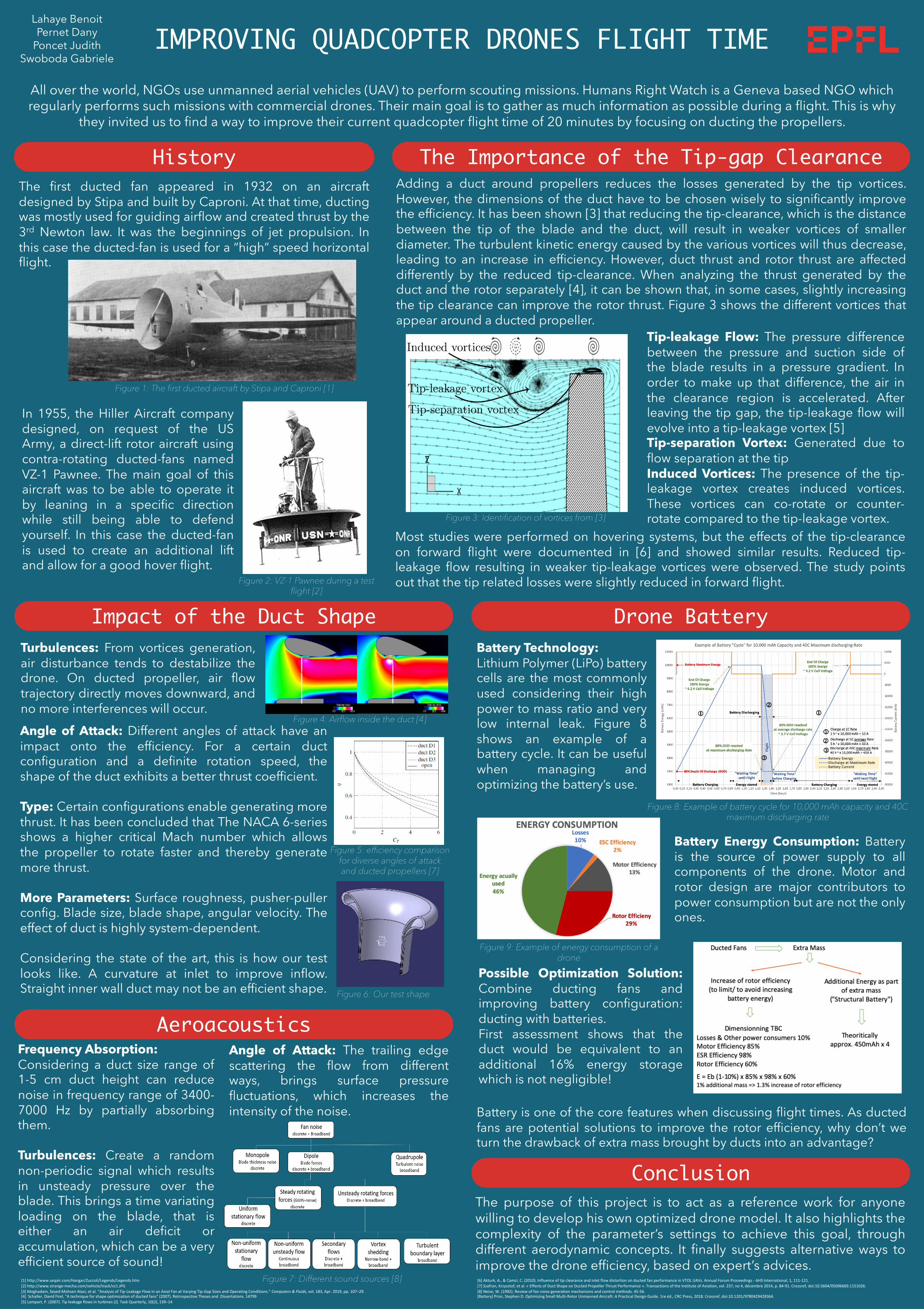
Figure 3: Identification of vortices from [3]
IMPROVING QUADCOPTER DRONES FLIGHT TIME
[1] http://www.seqair.com/Hangar/Zuccoli/Legends/Legends.htm[2] http://www.strange-mecha.com/vehicle/track/vz1.JPG[3] Moghadam, Seyed Mohsen Alavi, et al. “Analysis of Tip-Leakage Flow in an Axial Fan at Varying Tip-Gap Sizes and Operating Conditions.” Computers & Fluids, vol. 183, Apr. 2019, pp. 107–29.[4] Schaller, David Firel, "A technique for shape optimization of ducted fans" (2007). Retrospective Theses and Dissertations. 14799[5] Lampart, P. (2007). Tip leakage flows in turbines [J]. Task Quarterly, 10(2), 139–14
[6] Akturk, A., & Camci, C. (2010). Influence of tip clearance and inlet flow distortion on ducted fan performance in VTOL UAVs. Annual Forum Proceedings - AHS International, 1, 111-121.[7] Szafran, Krzysztof, et al. « Effects of Duct Shape on Ducted Propeller Thrust Performance ». Transactions of the Institute of Aviation, vol. 237, no 4, décembre 2014, p. 84-91. Crossref, doi:10.5604/05096669.1151026.[8] Neise, W. (1992). Review of fan noise generation mechanisms and control methods. 45-56.[Battery] Prior, Stephen D. Optimizing Small Multi-Rotor Unmanned Aircraft: A Practical Design Guide. 1re éd., CRC Press, 2018. Crossref, doi:10.1201/9780429428364.
Drone Battery
All over the world, NGOs use unmanned aerial vehicles (UAV) to perform scouting missions. Humans Right Watch is a Geneva based NGO which regularly performs such missions with commercial drones. Their main goal is to gather as much information as possible during a flight. This is why
they invited us to find a way to improve their current quadcopter flight time of 20 minutes by focusing on ducting the propellers.
Lahaye Benoit Pernet Dany
Poncet JudithSwoboda Gabriele
Impact of the Duct Shape
Possible Optimization Solution:Combine ducting fans andimproving battery configuration:ducting with batteries.First assessment shows that theduct would be equivalent to anadditional 16% energy storagewhich is not negligible!
HistoryThe first ducted fan appeared in 1932 on an aircraftdesigned by Stipa and built by Caproni. At that time, ductingwas mostly used for guiding airflow and created thrust by the3rd Newton law. It was the beginnings of jet propulsion. Inthis case the ducted-fan is used for a “high” speed horizontalflight.
In 1955, the Hiller Aircraft companydesigned, on request of the USArmy, a direct-lift rotor aircraft usingcontra-rotating ducted-fans namedVZ-1 Pawnee. The main goal of thisaircraft was to be able to operate itby leaning in a specific directionwhile still being able to defendyourself. In this case the ducted-fanis used to create an additional liftand allow for a good hover flight.
Figure 1: The first ducted aircraft by Stipa and Caproni [1]
Figure 2: VZ-1 Pawnee during a test flight [2]
Tip-leakage Flow: The pressure differencebetween the pressure and suction side ofthe blade results in a pressure gradient. Inorder to make up that difference, the air inthe clearance region is accelerated. Afterleaving the tip gap, the tip-leakage flow willevolve into a tip-leakage vortex [5]Tip-separation Vortex: Generated due toflow separation at the tipInduced Vortices: The presence of the tip-leakage vortex creates induced vortices.These vortices can co-rotate or counter-rotate compared to the tip-leakage vortex.
Adding a duct around propellers reduces the losses generated by the tip vortices.However, the dimensions of the duct have to be chosen wisely to significantly improvethe efficiency. It has been shown [3] that reducing the tip-clearance, which is the distancebetween the tip of the blade and the duct, will result in weaker vortices of smallerdiameter. The turbulent kinetic energy caused by the various vortices will thus decrease,leading to an increase in efficiency. However, duct thrust and rotor thrust are affecteddifferently by the reduced tip-clearance. When analyzing the thrust generated by theduct and the rotor separately [4], it can be shown that, in some cases, slightly increasingthe tip clearance can improve the rotor thrust. Figure 3 shows the different vortices thatappear around a ducted propeller.
Battery Technology:Lithium Polymer (LiPo) batterycells are the most commonlyused considering their highpower to mass ratio and verylow internal leak. Figure 8shows an example of abattery cycle. It can be usefulwhen managing andoptimizing the battery’s use.
Figure 6: Our test shape
Figure 4: Airflow inside the duct [4]
Figure 5: efficiency comparison for diverse angles of attack and ducted propellers [7]
Turbulences: From vortices generation,air disturbance tends to destabilize thedrone. On ducted propeller, air flowtrajectory directly moves downward, andno more interferences will occur.Angle of Attack: Different angles of attack have animpact onto the efficiency. For a certain ductconfiguration and a definite rotation speed, theshape of the duct exhibits a better thrust coefficient.
Type: Certain configurations enable generating morethrust. It has been concluded that The NACA 6-seriesshows a higher critical Mach number which allowsthe propeller to rotate faster and thereby generatemore thrust.
More Parameters: Surface roughness, pusher-pullerconfig. Blade size, blade shape, angular velocity. Theeffect of duct is highly system-dependent.
Considering the state of the art, this is how our testlooks like. A curvature at inlet to improve inflow.Straight inner wall duct may not be an efficient shape.
Battery is one of the core features when discussing flight times. As ductedfans are potential solutions to improve the rotor efficiency, why don’t weturn the drawback of extra mass brought by ducts into an advantage?
Most studies were performed on hovering systems, but the effects of the tip-clearanceon forward flight were documented in [6] and showed similar results. Reduced tip-leakage flow resulting in weaker tip-leakage vortices were observed. The study pointsout that the tip related losses were slightly reduced in forward flight.
The purpose of this project is to act as a reference work for anyonewilling to develop his own optimized drone model. It also highlights thecomplexity of the parameter’s settings to achieve this goal, throughdifferent aerodynamic concepts. It finally suggests alternative ways toimprove the drone efficiency, based on expert’s advices.
Figure 7: Different sound sources [8]
Frequency Absorption:Considering a duct size range of1-5 cm duct height can reducenoise in frequency range of 3400-7000 Hz by partially absorbingthem.
Turbulences: Create a randomnon-periodic signal which resultsin unsteady pressure over theblade. This brings a time variatingloading on the blade, that iseither an air deficit oraccumulation, which can be a veryefficient source of sound!
Conclusion
Aeroacoustics
Figure 8: Example of battery cycle for 10,000 mAh capacity and 40C maximum discharging rate
Figure 9: Example of energy consumption of a drone
Angle of Attack: The trailing edgescattering the flow from differentways, brings surface pressurefluctuations, which increases theintensity of the noise.
Battery Energy Consumption: Batteryis the source of power supply to allcomponents of the drone. Motor androtor design are major contributors topower consumption but are not the onlyones.