large aperture, solid surface deployable reflector aperture, solid surface deployable reflector...
TRANSCRIPT

This research is sponsored by the Earth Science Technology Office, Advanced Component Technology (ACT) program, contract #NNX09AD57G.
Large Aperture, Solid Surface Deployable Reflector
Robert Taylor, Dana Turse, Phil Keller, and Larry Adams Composite Technology Development (CTD)
2600 Campus Dr, Lafayette, CO 80027
Abstract- Composite Technology Development Inc. (CTD) is currently funded through the NASA Advanced Component Technology (ACT) program to develop an off-set fed, TEMBO® continuous composite surface deployable reflector for earth science applications. This type of reflector will offer a parabolic surface with the accuracy needed for RF science measurements to Ka band and beyond, including a clean aperture with no edge effects. The reflector will package for launch in 1/3 of its deployed width and can be sized for deployed apertures from 2.5m to 6m. A 4m development reflector is being built and tested to demonstrate these capabilities.
1. INTRODUCTION
Gathering of climate and Earth system data from space provides a unique opportunity to view the Earth as a whole, easily comparing conditions from area to area and providing the widest view of current conditions and best measure of changes over time. NASA is continually challenged to maintain and improve the gathering of essential Earth science data from orbit. Active and passive RF measurements provide much of this data, as indicated in [1]. This includes measurements for cloud height, glaciation height, wind speed and direction, precipitation, snowpack accumulation, snowpack water content, soil moisture, and freshwater surface level. Increased capability is a significant need for these measurements, and RF system performance is dependent upon aperture, especially for higher spatial resolution or increased gain. Larger apertures can be gained with deployable reflectors, and in recognition of this need, ESTO stated “technologies enabling large deployable Ka-band or higher spaceborne reflectors for Decadal Survey missions/measurements” are a high priority [2]. The TEMBO® solid-surface deployable reflectors being developed by CTD can provide larger apertures to enhance the performance of next generation systems for RF missions like SMAP, SWOT, XOVWM, ACE, PATH and SCLP.
2. CURRENT REFLECTOR TECHNOLOGY
Existing RF spacecraft reflectors typically fall into only two categories; rigid composite reflectors and deployable mesh reflectors. Rigid composite reflectors are mass efficient and provide precise surface contours in the operational environment, enabling high frequency measurements for a wide range of missions. However, the width of the aperture is limited to the width of the launch vehicle fairing. Deployable mesh antenna reflectors have proven to be a venerable product for low frequency, typically L-band, communications and
radar applications where high gain is required. These mesh reflectors are available up to extremely large apertures, but have not had the surface accuracy and surface reflectivity for performance at Ka band and above. Although efforts are underway to increase the frequency capability of some mesh reflectors, these efforts may add additional complexity and significant cost, to an already complex and expensive system.
Fig. 1 below shows how traditional rigid composite and deployable mesh reflectors have been baselined for previous and planned RF Earth Science missions. The operating frequencies chosen for different earth science measurements are dictated by the physics of each type of observation. The attainable resolution for the measurement is proportional to the aperture and inversely proportional to the frequency. Therefore, for similar measurement resolution, the aperture of the instrument should decrease as the frequency increases for different missions. However, Fig. 1 shows that existing and planned earth science RF missions instead have been more of a step function, with most missions using the same size reflector, around 1m, two missions using a 2.5m reflector and two that will use very large reflectors greater than 6m.
This step function matches the two common reflector types, with all but two missions optimized around the largest rigid reflector that could be packaged into the volume allocated for the payload. All of the RF missions utilizing 1m rigid reflectors are either dedicated small satellite missions or smaller payloads on large earth science platforms; thus the 1m size enables the reflectors to be packaged in a typical earth sensor payload allocation. In the case of the AQUARIUS and WindSat missions, a slightly larger aperture of 2.5m is
Fig. 1, Reflector Aperture Diameter of RF Earth Science Missions

attainable by dedicating the entire small launch vehicle envelope to the RF aperture. The newest missions that are still in development, SMAP and DESDynI, use very large mesh reflectors.
The information presented in Fig. 1 indicates that RF reflectors have generally been sized to fit smaller launch opportunities, regardless of the frequency. The solid surface deployable reflector technology enables larger apertures for applications that are currently restricted in size by launch volume and can’t justify the cost of a mesh reflector or operate at too high of a frequency for mesh. The oval in Fig. 1 represents the 4m to 6m range that could be available for certain missions that would benefit from increased data resolution capability.
3. SOLID-SURFACE DEPLOYABLE REFLECTOR
The development of a Large Aperture, Solid Surface Deployable Reflector is being funded through the ACT program with the goal of providing a new design for RF antenna reflectors, with larger apertures for operation from L through Ka bands. The solid surface deployable reflector meets the needs of science missions by providing a clean, continuous aperture for consistent data across the field of view. Significant progress has been made on the program, advancing the technology to TRL 3. All components of the system have been demonstrated and a 2.5m by 4m demonstration reflector is being fabricated. The reflective surface and backing structure are complete and tooling has been built to package and deploy the reflector.
CTD’s deployable solid surface reflectors are similar to rigid graphite reflectors, consisting of a front reflective surface and deep backing structure, as shown in Fig. 3. All components are fabricated using thermally stable graphite composite materials and conventional fabrication techniques. The reflective surface, or reflector shell, is a thin, conventional carbon fiber laminate that can be bent into a series of pleats and packaged to 1/3 of its original width as shown in Fig. 3. The backing structure is formed from graphite composite honeycomb panels which run parallel to the pleats. These panels are connected by deployable cross beams, which are installed perpendicularly to the panels. The cross beams are formed into reversing bends to reduce the width of the backing
structure by the same 1/3 ratio. The result is a thermally stable, deep composite structure that can be packaged into a significantly smaller volume. The stowed reflector can be packaged vertically into the launch vehicle, providing significantly more aperture than a rigid reflector for the same launch vehicle volume.
Pleating of the composite reflective surface and bending the cross beams connecting the backing structure creates significant strain energy that is stored while the reflector is in the packaged state. This strain energy is held during launch and gradually released on orbit by TEMBO® Elastic Memory Composite (EMC) materials, which are incorporated within four reflector shell stiffeners and eight cross beams as shown in Fig. 2. These TEMBO® components store strain energy through a thermo-mechanical stowage and deployment cycle as described in Section 4. Without this strain management, the reflector would explosively deploy when released and could not be restrained in the packaged shape without an impractical number of launch locks.
The reflector shell is manufactured using techniques established for rigid shell spacecraft reflectors. The shell is laid up on a bulk graphite mandrel using longitudinal gore sections for the reflective surface. The low CTE graphite fabric is applied as a no-bleed prepreg to maintain consistent fiber volume fraction in a very thin part. The reflector shell is stiffened in the longitudinal direction by integral composite ribs. The longitudinal ribs help maintain ‘form stability’ in the deployed shape, provide mounting locations on the reflector shell, and help manage the packaging of the reflector. The reflector shell is oven cured using only vacuum bag consolidation pressure. Ovens of sufficient size are available to CTD for reflectors as large as 6 meters in diameter.
The stiffened reflector shell is supported by a deployable backing structure. The backing structure provides significant structural depth and stability to the reflector system. Surface optimization of the reflective surface by iteratively adjusting the interface heights on the backing structure allows the surface to be tuned to the required level of accuracy. To allow pleating of the reflector shell, some of the contact points between the reflector and backing structure must separate during packaging and then return to a precise position upon deployment. CTD has demonstrated the effectiveness and efficiency of this assembly and tuning process on a previous NASA SBIR program. In the stowed configuration, the
Fig. 3, Stowed 4m Solid Surface Deployable Reflector Fig. 2, Deployed 4m Solid Surface Deployable Reflector
backing structure also supplies additional stiffness and strength for withstanding launch loading. The backing structure is held down with traditional launch locks and the stowed pleats of the shell are stabilized with lightweight blocks on the backside of the reflector.
4. REFLECTOR STOWAGE AND DEPLOYMENT CYCLE
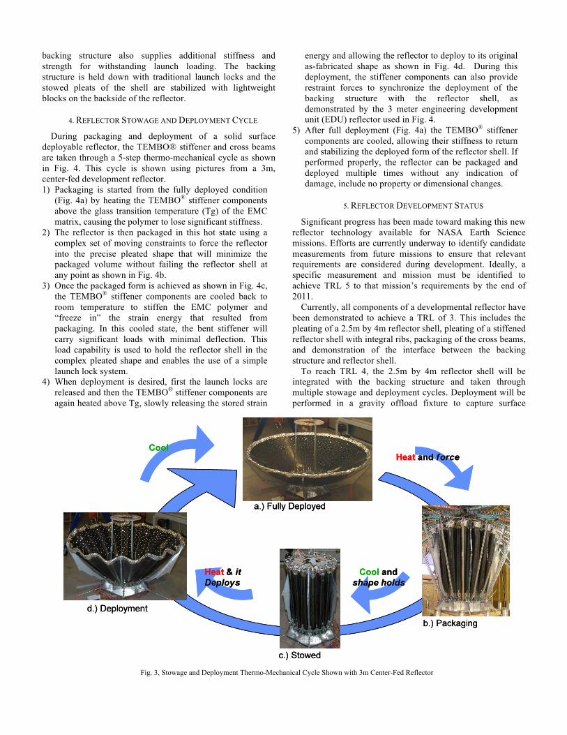
During packaging and deployment of a solid surface deployable reflector, the TEMBO® stiffener and cross beams are taken through a 5-step thermo-mechanical cycle as shown in Fig. 4. This cycle is shown using pictures from a 3m, center-fed development reflector. 1) Packaging is started from the fully deployed condition
(Fig. 4a) by heating the TEMBO® stiffener components above the glass transition temperature (Tg) of the EMC matrix, causing the polymer to lose significant stiffness.
2) The reflector is then packaged in this hot state using a complex set of moving constraints to force the reflector into the precise pleated shape that will minimize the packaged volume without failing the reflector shell at any point as shown in Fig. 4b.
3) Once the packaged form is achieved as shown in Fig. 4c, the TEMBO® stiffener components are cooled back to room temperature to stiffen the EMC polymer and “freeze in” the strain energy that resulted from packaging. In this cooled state, the bent stiffener will carry significant loads with minimal deflection. This load capability is used to hold the reflector shell in the complex pleated shape and enables the use of a simple launch lock system.
4) When deployment is desired, first the launch locks are released and then the TEMBO® stiffener components are again heated above Tg, slowly releasing the stored strain
energy and allowing the reflector to deploy to its original as-fabricated shape as shown in Fig. 4d. During this deployment, the stiffener components can also provide restraint forces to synchronize the deployment of the backing structure with the reflector shell, as demonstrated by the 3 meter engineering development unit (EDU) reflector used in Fig. 4.
5) After full deployment (Fig. 4a) the TEMBO® stiffener components are cooled, allowing their stiffness to return and stabilizing the deployed form of the reflector shell. If performed properly, the reflector can be packaged and deployed multiple times without any indication of damage, include no property or dimensional changes.
5. REFLECTOR DEVELOPMENT STATUS
Significant progress has been made toward making this new reflector technology available for NASA Earth Science missions. Efforts are currently underway to identify candidate measurements from future missions to ensure that relevant requirements are considered during development. Ideally, a specific measurement and mission must be identified to achieve TRL 5 to that mission’s requirements by the end of 2011.
Currently, all components of a developmental reflector have been demonstrated to achieve a TRL of 3. This includes the pleating of a 2.5m by 4m reflector shell, pleating of a stiffened reflector shell with integral ribs, packaging of the cross beams, and demonstration of the interface between the backing structure and reflector shell.
To reach TRL 4, the 2.5m by 4m reflector shell will be integrated with the backing structure and taken through multiple stowage and deployment cycles. Deployment will be performed in a gravity offload fixture to capture surface
Fig. 3, Stowage and Deployment Thermo-Mechanical Cycle Shown with 3m Center-Fed Reflector
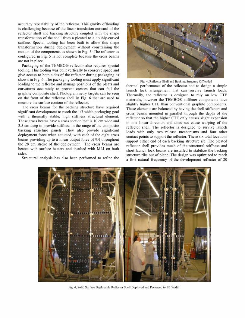
accuracy repeatability of the reflector. This gravity offloading is challenging because of the linear translation outward of the reflector shell and backing structure coupled with the shape transformation of the shell from a pleated to a doubly-curved surface. Special tooling has been built to allow this shape transformation during deployment without constraining the motion of the components as shown in Fig. 5. The reflector as configured in Fig. 5 is not complete because the cross beams are not in place.
Packaging of the TEMBO® reflector also requires special tooling. This tooling was built vertically to conserve space and give access to both sides of the reflector during packaging as shown in Fig. 6. The packaging tooling must apply significant loading to the reflector and manage positions of the pleats and curvatures accurately to prevent creases that can fail the graphite composite shell. Photogrammetry targets can be seen on the front of the reflector shell in Fig. 6 that are used to measure the surface contour of the reflector.
The cross beams for the backing structure have required significant development to reach the 1/3 width packaging goal with a thermally stable, high stiffness structural element. These cross beams have a cross section that is 10 cm wide and 3.5 cm deep to provide stiffness in the range of the composite backing structure panels. They also provide significant deployment force when actuated, with each of the eight cross beams providing up to a linear output force of 9N throughout the 28 cm stroke of the deployment. The cross beams are heated with surface heaters and insulted with MLI on both sides.
Structural analysis has also been performed to refine the
thermal performance of the reflector and to design a simple launch lock arrangement that can survive launch loads. Thermally, the reflector is designed to rely on low CTE materials, however the TEMBO® stiffener components have slightly higher CTE than conventional graphite components. These elements are balanced by having the shell stiffeners and cross beams mounted in parallel through the depth of the reflector so that the higher CTE only causes slight expansion in one linear direction and does not cause warping of the reflector shell. The reflector is designed to survive launch loads with only two release mechanisms and four other contact points to support the reflector. These six total locations support either end of each backing structure rib. The pleated reflector shell provides much of the structural stiffness and short launch lock beams are installed to stabilize the backing structure ribs out of plane. The design was optimized to reach a first natural frequency of the development reflector of 20
Fig. 4, Reflector Shell and Backing Structure Offloaded
Fig. 4, Solid Surface Deployable Reflector Shell Deployed and Packaged to 1/3 Width

Hz, however this could be increased depending upon mission requirements.
Planned work includes completion of the development reflector and testing to work towards TRL 5. This will include multiple stowage and deployment cycles to determine surface repeatability, thermal distortion testing to determine on-orbit distortion, and surface optimization to increase as-manufactured surface precision. Partnership with a specific mission is essential to refine the reflector requirements, identify performance gaps, and develop a detailed technology roadmap.
6. CONCLUSION
Larger apertures for an RF sensor can provide increased performance for any RF measurements that require an antenna reflector to concentrate the signal. This includes radiometer and radar applications for measurements of sea surface roughness, sea salinity, cloud profiling, atmospheric limb sounding, and snowpack characteristics. The solid surface deployable reflector provides a larger aperture by packaging to 1/3 width to allow the reflector to be mounted vertically in the launch vehicle. The reflector could be mounted to the RF instrument at the centerline keel or from an edge rib depending upon mission requirements. Also, to reduce the
stowed length, the reflector could fold in half after reducing the width with a corresponding increase in complexity.
Recent earth science missions including AQUARIUS and ACE have performed trade studies to consider ways to increase the available aperture to meet science goals. However, the cost, complexity and risk of existing deployable reflectors for these missions resulted in the selection of a smaller rigid reflector for the final flight configurations. The need for increased aperture has become apparent with dedicated earth science missions using large mesh reflectors currently in development. The solid surface deployable reflector provides an intermediate solution at lower cost and higher frequency to increase the performance capability for RF earth sensing missions of the future.
REFERENCES
[1] Committee on Earth Science and Applications from Space: A Community Assessment and Strategy for the Future, National Research Council, “Earth Science and Applications from Space: National Imperatives for the Next Decade and Beyond,” 2007.
[2] Earth Science Technology Office, “ROSES-2008 NASA
Research Announcement, A.21 Advanced Component Technology,” 2008.