large distractor – tibia. fracture reduction and ...synthes.vo.llnwd.net/o16/llnwmb8/int...
TRANSCRIPT

Tibial Distraction
Surgical Technique
Large Distractor – Tibia. Fracture reduction and provisional stabilization.
This publication is not intended for distribution in the USA.
Instruments and implantsapproved by the AO Foundation.

Image intensifier control
This description alone does not provide sufficient background for direct use of DePuy Synthes products. Instruction by a surgeon experienced in handling these products is highly recommended.
Processing, Reprocessing, Care and MaintenanceFor general guidelines, function control and dismantling of multi-part instruments, as well as processing guidelines for implants, please contact your local sales representative or refer to:http://emea.depuysynthes.com/hcp/reprocessing-care-maintenanceFor general information about reprocessing, care and maintenance of Synthes reusable devices, instrument trays and cases, as well as processing of Synthes non-sterile implants, please consult the Important Information leaflet (SE_023827) or refer to: http://emea.depuysynthes.com/hcp/reprocessing-care-maintenance
Large Distractor – Tibia Surgical Technique DePuy Synthes 1
Table of Contents
Introduction Standard Tibial Distraction, Intended Use, Warning 2
Surgical Technique Prepare Distractor 5
Universal Joint Assembly 6
Sliding Carriage Assembly 7
Tibial Distraction Technique Overview 8
Adjustment Technique 10
Product Information Instruments 13
Set List 16
MRI Information 17
Bibliography 18

2 DePuy Synthes Large Distractor – Tibia Surgical Technique
Standard Tibial Distraction, Intended Use, Warning
An alternative to the fracture table In the treatment of multitrauma patients, it is frequently more advantageous to perform surgical procedures on a standard operating table. The use of a fracture table can cause a loss of mobility of the limb, and mandates the surgical approach. The distractor allows free manipulation of the affected limb without the restrictions imposed by the fracture table.
Direct application of forceUnlike the fracture table, where force is applied to the fractured bone through adjacent joints and soft tissue structures, the distractor applies force directly to the bone, thus allowing repositioning of the fractured extremity while adjacent parts of the body remain undisturbed. This reduces the risk of nerve injuries and complications caused by the fracture table, including peroneal nerve palsy and pudendal crush syndrome.
Patient positioning Generally, patients with multiple injuries are placed supine on the fluoroscopy table. The entire limb is assessed with the C-arm in AP and lateral views.
Note: For a detailed handling description of the Schanz screws, refer to the Surgical Technique Schanz Screws and Steinmann Pins (DSEM/TRM/0516/0677).

Large Distractor – Tibia Surgical Technique DePuy Synthes 3
Intended useThe Large Distractor aids in fracture reduction and holds provisional stabilization prior to definitive fixation such as: – Distraction – Rotation – Valgus-varus – Anterior-posterior – Compression
Warning: The treating physician should make patient spe-cific clinical judgment and decision to use External Fixation System in patients with the following conditions: – Patients who for social and physical reasons are not
suitable for an external fixator. – Agitation – Patients in whom screws cannot be inserted due to a
bone or soft tissue disease.

4 DePuy Synthes Large Distractor – Tibia Surgical Technique
Relevant anatomy and pin placement
Proximal pin insertionThe proximal pin should be inserted from the posterior medial corner of the proximal tibia, aiming for the fibular head. Take care to avoid the medullary canal if IM nailing of the fracture will be attempted.
Distal pin insertionFor insertion in the distal tibia, the distal pin should be placed parallel to, and 5 to 10 mm above the tibia plafond, but distal to the physeal scar, and proximal to the medial malleolus. If IM nailing of very distal fractures will be attempted, the distal pin can also be positioned in the calcaneus, parallel to the coronal plane of the distal tibia. For pin insertion, care must be taken to avoid both intra- articular penetration and relevant neurovascular structures.
Tibial safe zones
Intended use
Optimal zones for Schanz Screw insertionRecommended zones for Schanz Screw insertion
Large Distractor – Tibia Surgical Technique DePuy Synthes 5
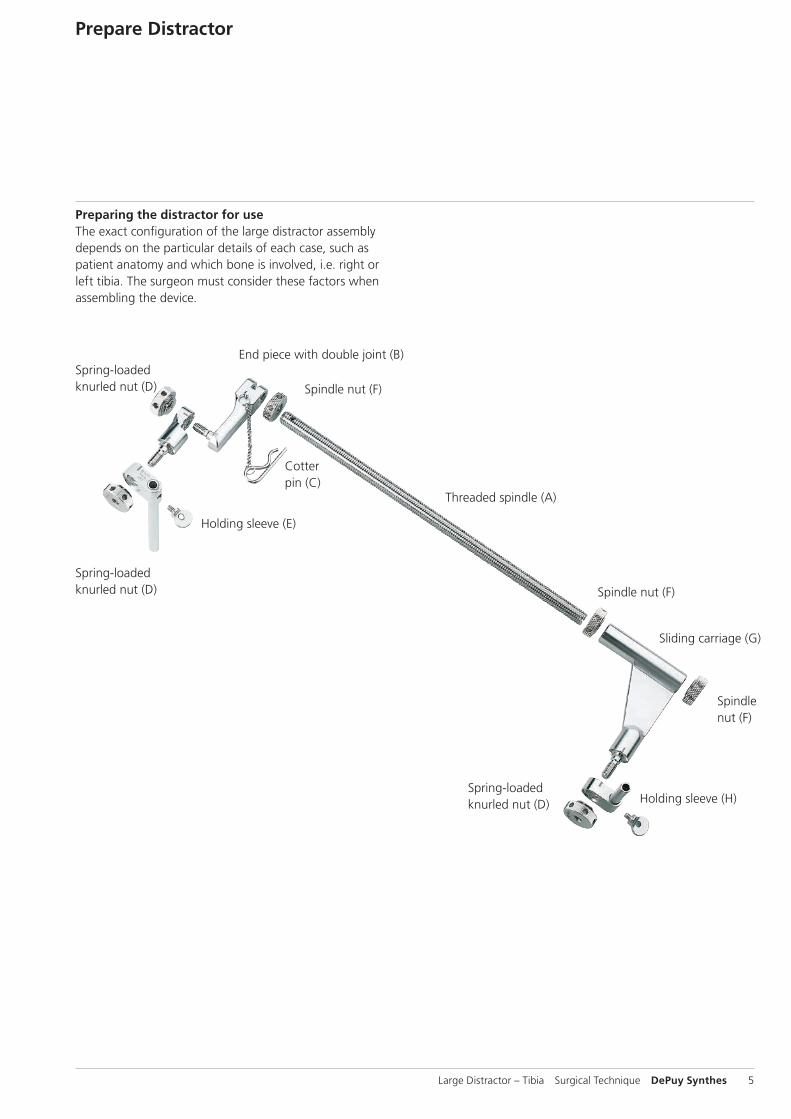
Prepare Distractor
Preparing the distractor for use The exact configuration of the large distractor assembly depends on the particular details of each case, such as patient anatomy and which bone is involved, i.e. right or left tibia. The surgeon must consider these factors when assembling the device.
Spindle nut (F)
End piece with double joint (B)
Spindle nut (F)
Sliding carriage (G)
Threaded spindle (A)
Spindle nut (F)
Cotter pin (C)
Holding sleeve (E)
Spring-loaded knurled nut (D)
Spring-loaded knurled nut (D)
Spring-loaded knurled nut (D) Holding sleeve (H)

C
B
C
D
E
A
6 DePuy Synthes Large Distractor – Tibia Surgical Technique
Universal Joint Assembly
1Select a 14.0 mm threaded spindle (A) of appropriate length. A transverse hole will be in the distal end when applied to the tibia.
2 Turn the end piece with double joint (B) onto the threaded spindle so that the rod and end piece are flush. If the end piece is positioned correctly, the transverse hole will be centered in the slot of the end piece.
3 To lock rotation of the end piece with double joint, push the cotter pin (C) through the hole until it snaps into place. Extend the end piece so that the reference marks align, and hand-tighten the spring-loaded knurled nut (D).
4 Mount the appropriate length holding sleeve (E) onto the end piece so that the serrated ends interface and the reference marks align. To secure the holding sleeve, put the spring-loaded knurled nut on the end piece and hand-tighten.

F G
HE
Large Distractor – Tibia Surgical Technique DePuy Synthes 7
Sliding Carriage Assembly
5Thread a spindle nut (F) partway down the 14.0 mm threaded spindle. Place the sliding carriage (G) over the threaded spindle, and secure it with a second spindle nut.
6Mount the other holding sleeve (H or E) onto the sliding carriage. The serrated ends must interface and the reference marks must align. Put the spring-loaded knurled nut on the sliding carriage to secure the holding sleeve and hand-tighten.
Precautions: – Instruments and screws may have sharp edges or moving
joints that may pinch or tear user’s glove or skin. – Handle devices with care and dispose worn bone cutting
instruments in an approved sharps container.

8 DePuy Synthes Large Distractor – Tibia Surgical Technique
1Insert proximal Schanz screw
Instruments
294.540 Schanz Screw B 5.0 mm, length 150/50 mm, Stainless Steel
294.550 Schanz Screw B 5.0 mm, length 175/50 mm, Stainless Steel
294.560 Schanz Screw B 5.0 mm, length 200/50 mm, Stainless Steel
393.100 Universal Chuck with T-Handle
The proximal Schanz screw should be placed 14 mm inferior and parallel to the tibial plateau. Starting from the posterior medial corner of the proximal tibia, insert the Schanz screw laterally, aiming for the fibular head.
2Insert distal Schanz screw
The distal Schanz screw should be placed 10 mm above and parallel to the tibial plafond.
Note: For extreme distal tibia fractures, there is the option of inserting the distal pin through the tuberosity of the calcaneus. To avoid the neurovascular bundle in this area, the pin should be placed well posterior and inferior on the calcaneus. Typically, the ideal insertion site lies two fingerbreadths from the plantar aspect of the heel, and two fingerbreadths anterior to the dorsal aspect of the heel. The pin should be parallel to the coronal plane of the distal tibia.
Precautions: – The tip of the Schanz screw should be embedded in
the far cortex to effectively resist cantilever forces and to provide sufficient stability.
– Only when bones are osteoporotic, the Schanz screw has to be screwed a bit further into the distant cortical bone, and it may even slightly penetrate through it since this can increase anchoring stability.
Tibial Distraction Technique Overview

1
4
2 4
3
Large Distractor – Tibia Surgical Technique DePuy Synthes 9
3Attach distractor
Instruments
321.170 Pin Wrench B 4.5 mm, length 120 mm
394.350 Large Distractor, complete
Handling the preassembled distractor as a unit, slide the proximal holding sleeve (on the sliding carriage) over the proximal Schanz screw. The 14.0 mm threaded spindle should be medial and posterior to the axis of the tibia. Slide the distal holding sleeve (with double-jointed end piece) onto the distal Schanz screw. Temporarily loosen the spring-loaded knurled nut or the spindle nuts, as needed. The holding sleeves should be placed firmly against the bone.
4Tighten wing screws
Instruments
321.170 Pin Wrench B 4.5 mm, length 120 mm
393.100 Universal Chuck with T-Handle
Securely tighten the holding sleeves on the Schanz screws by tightening the wing screws using the 4.5 mm pin wrench. If the distractor is positioned properly, the threaded spindle will parallel the axis of the distal tibia. Tighten all spring-loaded knurled nuts in the neutral position.
Note: For segmental fractures, an additional Schanz screw can be inserted into the middle fracture segment, and manipulated into position with the aid of the universal chuck with T-handle.

2 1
2 1
3
10 DePuy Synthes Large Distractor – Tibia Surgical Technique
Adjustment Technique
2Rotation
Instrument
321.170 Pin Wrench B 4.5 mm, length 120 mm
Loosen both spindle nuts (1 and 2) and the spring-loaded knurled nut (3) on the end piece with double joint. Correct rotation by simultaneously rotating the sliding carriage and the 14.0 mm threaded spindle.
With all connections loose (except wing screws), obtain approximate alignment and rotation. When the position is acceptable, securely tighten all loose connections with the 4.5 mm pin wrench.
1Distraction
Instrument
321.170 Pin Wrench B 4.5 mm, length 120 mm
Loosen the proximal spindle nut (1). Under image intensification, apply distraction by moving the distal spindle nut (2) proximally.

4
5
Large Distractor – Tibia Surgical Technique DePuy Synthes 11
3Valgus-Varus
Instrument
321.170 Pin Wrench B 4.5 mm, length 120 mm
Loosen the spring-loaded knurled nut on the distal holding sleeve (4). Correction is achieved by manipulating the distal Schanz screw with the universal chuck with T-handle.
4Anterior-posterior angulation
Instrument
321.170 Pin Wrench B 4.5 mm, length 120 mm
Loosen the wing screw (5) that secures the proximal Schanz screw in the proximal holding sleeve and correct the anterior-posterior angulation.

12
12 DePuy Synthes Large Distractor – Tibia Surgical Technique
5Compression
Instrument
321.170 Pin Wrench B 4.5 mm, length 120 mm
Loosen the distal spindle nut (2). Under image intensification, apply compression by moving the proximal spindle nut (1) distally.
After reduction, secure distractor joints by tightening all connections.
Note: Manipulation of the distractor for reduction of the tibia is similar to that of the femur, although the instrumentation is oriented in the opposing direction. These steps need not be performed in the order given, except for Step 5 (compression), which should be performed last. To avoid loss of correction, retighten all loosened nuts after each step.
Precautions: – Implant sites should be meticulously cared to avoid pin-
tract infection. Schanz screws may be surrounded with antiseptic coated foam sponges in an effort to avoid in-fection. An implant-site care procedure should be re-viewed with the patient.
– To minimize the risk of pin track infection, the following points should be observed:a. Placement of Schanz screws taking anatomy into
consideration (ligaments, nerves, arteries).b. Slow insertion and/or cooling, particularly in dense,
hard bone to avoid heat necrosis.c. Release of skin tension at soft tissue entry point of
implant.
Adjustment Technique

Large Distractor – Tibia Surgical Technique DePuy Synthes 13
Product Information
Instruments
294.540 Schanz Screw B 5.0 mm, length 150/50 mm, Stainless Steel
294.550 Schanz Screw B 5.0 mm, length 175/50 mm, Stainless Steel
294.560 Schanz Screw B 5.0 mm, length 200/50 mm, Stainless Steel
310.370 Drill Bit B 3.5 mm, length 195/170 mm, 2-flute, for Quick Coupling
321.160 Combination Wrench B 11.0 mm
321.170 Pin Wrench B 4.5 mm, length 120 mm
393.100 Universal Chuck with T-Handle

14 DePuy Synthes Large Distractor – Tibia Surgical Technique
Product InformationInstruments
394.420 Nut, knurled, for Large Distractor
394.182 Trocar B 3.5 mm, long
394.350 Large Distractor complete
394.410 Threaded Rod B 14.0 mm, length 330 mm, for Large Distractor
394.400 Threaded Rod B 14.0 mm, length 480 mm, for Large Distractor
393.830 Drill Sleeve 6.0/5.0, long
393.790 Drill Sleeve 5.0/3.5, long
Large Distractor – Tibia Surgical Technique DePuy Synthes 15
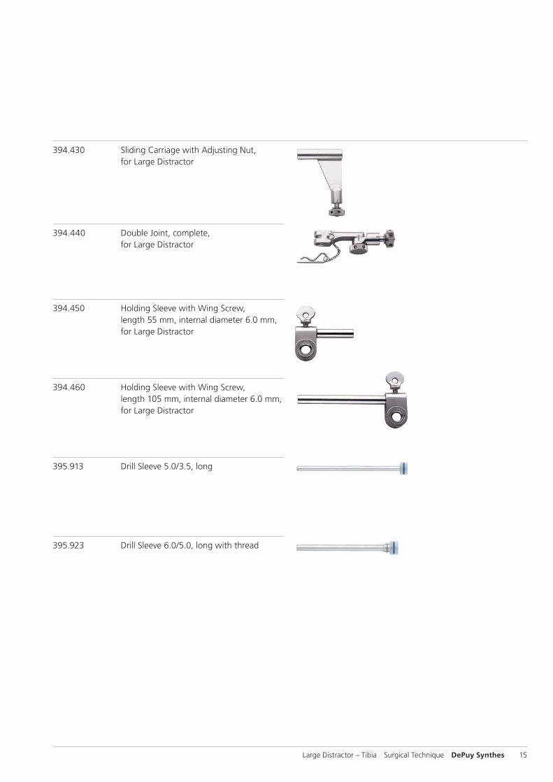
394.430 Sliding Carriage with Adjusting Nut, for Large Distractor
394.440 Double Joint, complete, for Large Distractor
394.450 Holding Sleeve with Wing Screw, length 55 mm, internal diameter 6.0 mm, for Large Distractor
394.460 Holding Sleeve with Wing Screw, length 105 mm, internal diameter 6.0 mm, for Large Distractor
395.913 Drill Sleeve 5.0/3.5, long
395.923 Drill Sleeve 6.0/5.0, long with thread

16 DePuy Synthes Large Distractor – Tibia Surgical Technique
68.120.510 Modular Tray for Instrument Set for Large Distractor, without Contents
Content of Instrument Set Units
310.370 Drill Bit B 3.5 mm, length 195/170 mm, 2 2-flute, for Quick Coupling
321.160 Combination Wrench B 11.0 mm 1
321.170 Pin Wrench B 4.5 mm, length 120 mm 1
393.100 Universal Chuck with T-Handle 1
393.790 Drill Sleeve 5.0/3.5, long 1
393.830 Drill Sleeve 6.0/5.0, long 1
394.160 Trocar B 3.5 mm, long 1
394.400 Threaded Rod B 14.0 mm, 1 length 480 mm, for Large Distractor
394.410 Threaded Rod B 14.0 mm, 1 length 330 mm, for Large Distractor
394.420 Nut, knurled, for Large Distractor 3
394.430 Sliding Carriage with Adjusting 1 Nut, for Large Distractor
394.440 Double Joint, complete, 1 for Large Distractor
394.450 Holding Sleeve with Wing Screw, 2 length 55 mm, internal diameter 6.0 mm, for Large Distractor
394.460 Holding Sleeve with Wing Screw, 2 length 105 mm, internal diameter 6.0 mm, for Large Distractor
294.540 Schanz Screw B 5.0 mm 4 length 150/50 mm, Stainless Steel
294.550 Schanz Screw B 5.0 mm, 4 length 175/50 mm, Stainless Steel
294.560 Schanz Screw B 5.0 mm, 4 length 200/50 mm, Stainless Steel
Set List
Product Information

Large Distractor – Tibia Surgical Technique DePuy Synthes 17
MRI Information
The “Large Distractor – Tibia” is MR unsafe. Do not use this device in any MR environment. This device is known to pose hazards in all MR environments.

18 DePuy Synthes Large Distractor – Tibia Surgical Technique
Bibliography
ReferencesMoed, B.R., Watson, J.T. “Intramedullary Nailing of the Tibia without a Fracture Table: The Transfixation Pin Distractor Technique.” Journal of Orthopaedic Trauma. 1994; 8;3. 195–202
Moed, B.R., Watson, J.T. “Intramedullary Nailing of Aseptic Tibial Nonunions Without the Use of a Fracture Table.” Journal of Orthopaedic Trauma. 1995; 9;2. 128–134
Fernandez, A. “External Fixation.” AO Principles of Fracture Management.
Ruedi, T. and Murphy, W., ed. Dubendork, Switzerland; AO Publishing. 2000. 239
Illustrations modified and used with permission.


Synthes GmbHEimattstrasse 34436 OberdorfSwitzerlandTel: +41 61 965 61 11Fax: +41 61 965 66 00www.depuysynthes.com 0123 ©
DeP
uy S
ynth
es T
raum
a, a
div
isio
n of
Syn
thes
Gm
bH. 2
016.
A
ll rig
hts
rese
rved
. 03
6.0
00.
038
DSE
M/T
RM
/101
5/05
43(1
) 07
/16
Not all products are currently available in all markets.
This publication is not intended for distribution in the USA.
All surgical techniques are available as PDF files at www.depuysynthes.com/ifu