large scale shearography inspection of the space · pdf fileasnt spring conf. 2010 1 large...
TRANSCRIPT

ASNT Spring Conf. 2010 1
Large Scale Shearography Inspection of the Space Shuttle External Fuel Tank
Warren UsseryLockheed Martin Space Systems CompanyMichoud Assembly Facility504-257-1834
Phillip ScheurerLockheed Martin Space Systems CompanyMichoud Assembly Facility504-257-2068
Joanna RiversLockheed Martin Space Systems CompanyMichoud Assembly Facility504-257-1833
James WalkerNASAMarshall Space Flight Center256-961-1784
Donald LovellSynder Technical ServicesMarshall Space Flight Center256-544-0108
https://ntrs.nasa.gov/search.jsp?R=20100017430 2018-05-03T23:39:59+00:00Z

ASNT Spring Conf. 2010 2
• External Propellant Tank (ET) Background– ET holds cryogenic liquid hydrogen and oxygen fuel
for shuttle main engines
– Polyurethane foam insulation prevents cryogenic fuel from boiling as well as ice formation
– Aero loads during launch can produce foam debris potentially damaging the shuttle orbiter
– After the Columbia accident, ET foam debris was identified as a likely cause of the orbiter wing damage
– Several NDE methods including shearography were developed for foam inspection to minimize debris damage to orbiter
Background: External Propellant Tank
External Fuel Tank
ASNT Spring Conf. 2010 3
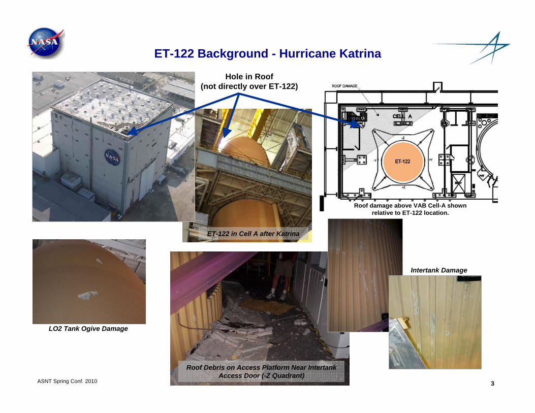
ET-122 Background - Hurricane Katrina
ET-122 in Cell A after Katrina
Hole in Roof(not directly over ET-122)
Roof damage above VAB Cell-A shownrelative to ET-122 location.
LO2 Tank Ogive Damage
Intertank Damage
Roof Debris on Access Platform Near Intertank Access Door (-Z Quadrant)

ASNT Spring Conf. 2010 4
ET-122 RestorationThermal Protection System Assessment
• Objective– Perform Shearography to inspect for non-visible damage including:
• Crushed foam• Delaminations• Embedded debris
– Provide a screening test that could be confirmed with follow up visual and tactile inspections
Delamination
Embedded DebrisCrushed Foam
SEM Photomicrograph of Intact Foam Cells
Three Types of Damage Assessed with Shearography Inspection

ASNT Spring Conf. 2010 5
ET-122 RestorationShearography Assessment
Method Description• Shearography (Shearing Holography) is an inspection
technique that detects minute changes of shape of a part due to heat, vacuum or another form of agitation.
• The system measures the interference pattern generated by two sheared laser speckle images before and after loading.
• The result of the interference pattern is a measure of the change in out of plane surface slope which can be directly related to the local stiffness of the structure under test.
Equipment• A Laser Technologies Inc. Model 5100 shearographic
system along with heat lamps, vacuum, acoustic and vibration sources for structural excitation
Advantages• Useful in detecting and sizing voids, delaminations,
contamination, cracks, material inconsistencies in coatings and paints, insulation layers, and polymer or elastomer based structural materials
• The shearographic method images a large area (up to several square feet) of the part under test providing a rapid, near real time, inspection.
Limitations• The part under test must have a matte, light colored,
surface that will reflect the laser speckle without glare. • The test article must be stable and not move during the
acquisition time. • The interpretation on the images requires some training and
is not as intuitive as other imaging techniques.
Imager/Laser
Acoustic source
Acoustic Stress
100 dB SPL
Defect vibrates under acoustic load

ASNT Spring Conf. 2010 6
Sound Meter
Camera/Laser
Data acquisition and system control cart
Tank inspection fixtureBldg 420
Test Procedure:QTI-N-044 Drafted
“Shearographic Inspection of the External Tank”
ET-122 RestorationShearography Assessment
• Background – Shearography System
Shearography Using Acoustic Stressing Performed on 8 External Tanks to Date

ASNT Spring Conf. 2010 7
ET-122 RestorationShearography Assessment
• Background - POD Summary– POD Test Plan was developed following the guidelines of MIL-HNBK-1823– Multiple inspectors participated in study– 100 defects and 300 blanks were used to evaluate detection and false call rates– POD studies completed for non-visible crush damage and delaminations– Worst case POD value for shearography on net spray foam:
• Crushed foam is 0.43” deep• Delamination 1.18” diameter
– False positive rate established• No false positive results at or above critical flaw size
– MSFC FCB reviewed and concurred with shearography POD for detection of crush damage and delaminations

ASNT Spring Conf. 2010 8
ET-122 RestorationThermal Protection System Assessment
• Issues– Large inspection area– Accurate positioning of inspection grid– Access to +Z ogive region– Detection threshold for embedded concrete
Scissors lifts and stands provide access to all inspection regions
except +Z, or top, of tank
Difficult geometries such as stringers and carrier support arm
require angled shots

ASNT Spring Conf. 2010 9
Crush Damage
Concrete Chip
Test Panel Shearography Image of Test Panel
ET-122 RestorationShearography Assessment
• Shearography on Acreage with Crush Damage and Embedded Concrete– Test panel with net spray NCFI– Simple geometry allows optimal inspection– Test article contained 1/8” concrete chip embedded in foam plus crush damage– One foot field of view to detect 1/8” concrete chip– Smaller concrete chips were not reliably detected

ASNT Spring Conf. 2010 10
ET-122 RestorationShearography Assessment
• Shearography on Stringers with Embedded Concrete– Stringer geometry introduces difficulties– Test article is approx. stringer geometry with approx. 1/8” concrete chips embedded– At approx. 30° off normal, concrete chips are detected on top and side of stringer– Stringer inspections will require two shots, at ±30° to capture tops and sides of stringers
Test Panel with Three Concrete Chips

ASNT Spring Conf. 2010 11
SLA-22 Shearography fixture at KSC (VAB Check-out Cell)
Acreage Shearography fixture at MAF (Bldg 420)
ET-122 RestorationShearography Assessment
• Shearography System Positioning Fixtures
Shearography System
Shearography System

ASNT Spring Conf. 2010 12
ET-122 RestorationShearography Assessment
• Shearography Inspections Were Performed in Three configurations– -Z region: modified Genie Lift tool adapted for shearography camera– Region below +Y and -Y: SLA tool (another modified Genie Lift model)– Region above +Y and -Y: Crane mounted tool
-Z Inspection -Y and +Y Inspection
+Z Inspection

ASNT Spring Conf. 2010 13
ET-122 RestorationShearography Assessment
• Shearography Inspection Approach – Inspection Layout
• Regions were identified by ogive, barrel, or inter tank panel• Inspections were performed by panel to work with manageable sizes• An LCD projector was used to project an Excel worksheet onto the panel• The Excel grid was adjusted to provide 12” cells
Excel grid
Welds act as landmarks for each inspection region
ASNT Spring Conf. 2010 14
ET-122 RestorationShearography Assessment
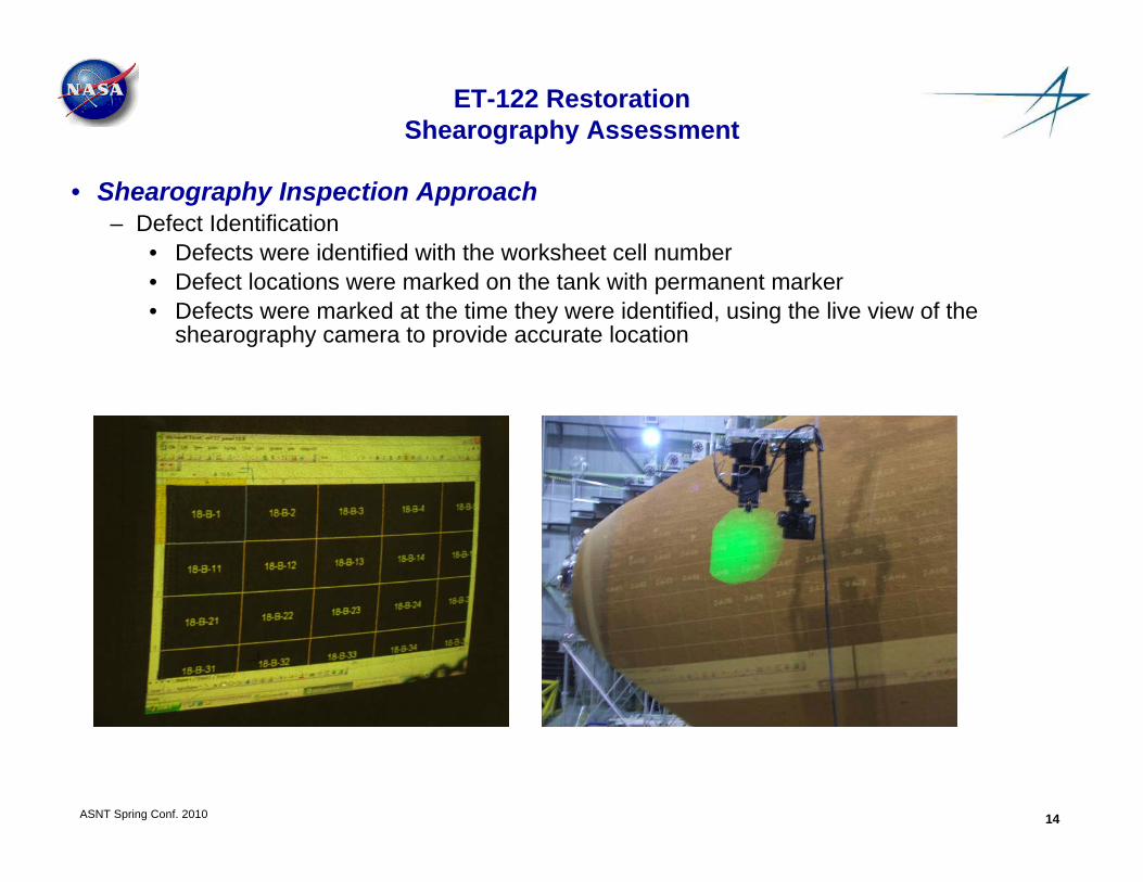
• Shearography Inspection Approach – Defect Identification
• Defects were identified with the worksheet cell number• Defect locations were marked on the tank with permanent marker• Defects were marked at the time they were identified, using the live view of the
shearography camera to provide accurate location

ASNT Spring Conf. 2010 15
ET-122 RestorationShearography Assessment
• Shearography Acoustic Stressing Technique– Band limited white noise in the audio frequency range– Intensity 105 ±5dB at part– Frequency bands are established to distinguish deeper delaminations from near surface
crush damage– Higher frequencies detect crush damage but not delaminations
Delamination Test PanelNo response in the mid to high frequency range
Crush Damage Test PanelResponse in the mid to high frequency range
Low Freq Band 1 Low Freq Band 2 Mid Freq Band 1
Mid Freq Band 2 High Freq Band 1 Broad Band
Low Freq Band 1 Low Freq Band 2 Mid Freq Band 1
Mid Freq Band 2 High Freq Band 1 Broad Band

ASNT Spring Conf. 2010 16
ET-122 RestorationShearography Assessment
• Shearography Results - Examples
Visible IndicationStrong Shearography response and damage was visibly evident
Non-visible IndicationStrong Shearography response but no visible damage on tank
Embedded Concrete ChipStrong Shearography response, small
but visible damage on tank

ASNT Spring Conf. 2010 17
ET-122 RestorationShearography Assessment
• Shearography Results– 95 total defect indications– 74 indications involved visible TPS damage– 21 indications exhibited no visible damage– Two occurrences of embedded concrete chips were detected
Distribution of Defect Indications by Size
Distribution of Visible and Nonvsible Defect Indications
0102030405060
0 to 1 1 to 4 4 to 10 10 to 24
Square Inches
Visible Defect Indications
Nonvisible DefectIndications
56
15 10 5 53
ASNT Spring Conf. 2010 18
ET-122 RestorationShearography Assessment
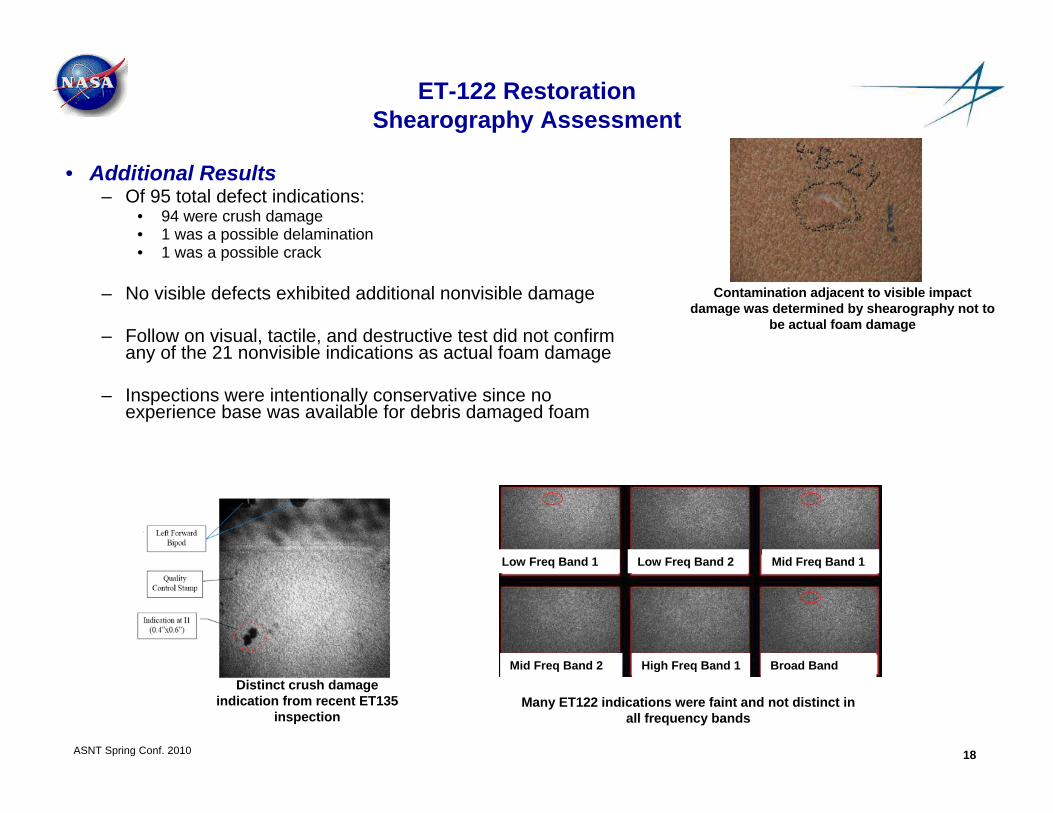
• Additional Results– Of 95 total defect indications:
• 94 were crush damage• 1 was a possible delamination• 1 was a possible crack
– No visible defects exhibited additional nonvisible damage
– Follow on visual, tactile, and destructive test did not confirm any of the 21 nonvisible indications as actual foam damage
– Inspections were intentionally conservative since no experience base was available for debris damaged foam
Contamination adjacent to visible impact damage was determined by shearography not to
be actual foam damage
Distinct crush damage indication from recent ET135
inspectionMany ET122 indications were faint and not distinct in
all frequency bands
Low Freq Band 1 Low Freq Band 2 Mid Freq Band 1
Mid Freq Band 2 High Freq Band 1 Broad Band

ASNT Spring Conf. 2010 19
ET-122 RestorationShearography Assessment
• Conclusions– Shearography was successfully used to inspect the damaged region of ET122 for nonvisible
damage
– The shearography inspection was extensive covering over 3100 square feet of foam and lasting 9 months
– Most foam damage was visible and shearography results confirmed that foam damage in visibly impacted regions did not extend outside the area with visible damage
– Of the 21 nonvisible defect indications detected with shearography, none were determined to be actual foam damage
– Inspections were intentionally conservative since no experience base was available for debris damaged foam
– Shearography results were used in conjunction with tactile and visual inspection to support the acceptance of the foam application allowing the tank to move forward for refurbishment