laser marking technology - laser manufacturer & supplier in
TRANSCRIPT

Sintec Optronics Pte Ltd
URL: http://www.SintecOptronics.com http://www.SintecOptronics.com.sg 1
LASER MARKING TECHNOLOGIES
Sintec Optronics Pte Ltd 196 Pandan Loop #07-26 Pantech Ind Complex Singapore 128384
Tel: +65-67781866 Fax: 67781781 E-mail: [email protected]

Sintec Optronics Pte Ltd
URL: http://www.SintecOptronics.com http://www.SintecOptronics.com.sg 2
1. Introduction 2. Advantages of laser marking 3. Marking methods in laser marking technologies 3.1 Mask marking 3.2 Beam deflected marking 3.3 Comparison of mask marking and beam deflected marking 3.4 Comparison of laser vs. other marking technologies 3.5 Cost justification 4. Lasers in laser marking 4.1 Laser resonator and modes 4.2 CO2 lasers 4.3 Nd:YAG lasers 4.4 Excimer lasers 4.5 Laser marking system evaluation 5. Major components & calculation in laser marking 5.1 Q-switch element 5.2 Beam expander 5.3 F-θ lens 5.4 Beam homogeniser 6. Laser marking mechanism and quality characteristics 6.1 Surface material removal 6.2 Marking quality characteristics 6.3 Process parameters 7. Laser marking examples 7.1 Laser marking on IC packages 7.2 Laser marking on PCBs 7.3 Laser marking of polymers 8. References

Sintec Optronics Pte Ltd
URL: http://www.SintecOptronics.com http://www.SintecOptronics.com.sg 3
1. Introduction Light has much relationship with nature matters and living species, since light has a very wide range in its wavelength spectrum (near zero to about 100 mm) and has been underlying in almost every activities of life. Since 1960, when the first laser was operated, extensive research and development have been undertaken leading to a rapid growth in laser types, output power and scope of applications. The reason for the rapid development in laser technology lies in five distinct properties of the laser beam: monochromaticity, coherence, good directionality, high brightness, and short pulse duration. Now lasers are widely used in almost every field of industry, agriculture, research and development, military, education, and daily-used appliance. For example, CO2 lasers have been finding wide use in almost every aspects of laser material processing such as cutting, welding, cladding, and heat treatment. It is currently the most powerful material processing laser with commercial laser being offered up to 45 kW. Nd:YAG lasers are being widely used in laser drilling, marking, and cutting. Diode-pumped solid state lasers have been finding more applications in semiconductor fabrication/repair, micro-material processing, medical diagnostics because of their all solid state reliability, high efficiency, and long life time. Since the short wavelengths of excimer lasers permit both fine spatial resolution and cold ablative processing, excimer lasers have developed from physicists' "toys" to powerful tools in material processing since their initial demonstration 20 years ago. It is reported that the world commercial sales of diode lasers and nondiode lasers are 84,370,408 and 361,581 units respectively, reaching US$264.5 and US$700.5 millions respectively in 1994. Product laser marking is one of the most common industrial applications of lasers. The laser marking systems using different lasers and optical delivery systems may be used to mark an almost endless list of materials including metals, plastics, ceramics, glass, wood and leather as well as painted surfaces and photographic emulsions. 2. Advantages of laser marking As we know, information sinformation such as part number, operating instructions, date of manufacture, logos, etc., is needed for typical quality control monitoring as well as consumer protection. A wide variety of marking and labelling methods has been developed. Examples include pen or pencil writing, press labelling, and ink-stamp marking. Each method has its own advantages and disadvantages. Label markings, for instance, are generally not permanent. Even through ink markings can produce very legible and permanent writings, the method involves many imprecise and time-consuming steps. Furthermore, this method is not satisfactory for marking minute objects or large objects with very small print. In addition, there are complications associated with equipment maintenance and control of the print quality. Laser marking most commonly takes the form of an alphanumeric code imprinted on the surface of the product to indicate the date of manufacture, best-before, serial number etc. Therefore, it is a surface process. The marking processes include one or a combination of the following processes: (1) black carbonisation; (2) bleaching or changing the colour of a colorant in the material;

Sintec Optronics Pte Ltd
URL: http://www.SintecOptronics.com http://www.SintecOptronics.com.sg 4
(3) physical modification of the surface finish; (4) scribing a shallow groove into the material by vaporisation; (5) highly-controlled modification of the surface by melting. Laser marking is superior in quality and flexibility to traditional marking techniques; it leads itself to automation and integrated production techniques. The common advantages of all laser marking techniques are (1) permanent, high quality marks; (2) high efficiency and low operation cost; (3) good accessibility, even to irregular surface; (4) non-contact marking and no special working environmental needed; (5) easy to automate and integrate (direct writing of patterns can established
using computer-controlled movement of the beam or sample); (6) precise beam positioning and a beam highly localised energy transfer to
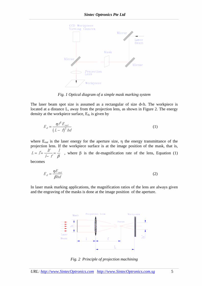
the workpiece (a narrow damage zone); (7) high reproducibility, high speed and throughput; and (8) contamination - free. 3. Marking methods in laser marking technologies There are two basic methods for laser marking: they are mask marking and beam deflected marking. Both methods take advantage of the relatively high powers generated by lasers. Both methods also use optical techniques to enhance the power densities to levels sufficient to etch the surface of the material to be marked. 3.1 Mask marking In mask marking, a stencil of the desired mark is projected onto the workpiece. The picture of the mask on the object is made using a lens. An extremely short impulse of light energy is directed on the workpiece. Therefore, employed in the mask marking are often the pulsed lasers such as pulsed TEA CO2 laser, excimer laser, and pulsed Nd:YAG laser. Figure 1 shows the optical diagram of a simple mask marking system. An image of the mask (or the aperture) is projected with high resolution onto the workpiece through a projection lens to ablate and process materials.
Sintec Optronics Pte Ltd
URL: http://www.SintecOptronics.com http://www.SintecOptronics.com.sg 5
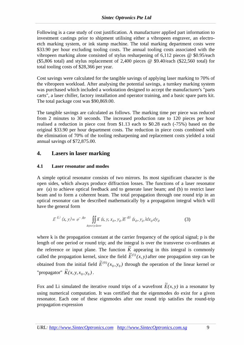
Fig. 1 Optical diagram of a simple mask marking system The laser beam spot size is assumed as a rectangular of size d×h. The workpiece is located at a distance L, away from the projection lens, as shown in Figure 2. The energy density at the workpiece surface, Ed, is given by
( )
Ef E
L f hdd
out=−
η 2
2 (1)
where Eout is the laser energy for the aperture size, η the energy transmittance of the projection lens. If the workpiece surface is at the image position of the mask, that is,
L llf
l f
l= =
−='β
, where β is the de-magnification rate of the lens, Equation (1)
becomes
EE
hddout=
ηβ
(2)
In laser mask marking applications, the magnification ratios of the lens are always given and the engraving of the masks is done at the image position of the aperture.
Fig. 2 Principle of projection machining

Sintec Optronics Pte Ltd
URL: http://www.SintecOptronics.com http://www.SintecOptronics.com.sg 6
The following are some experimental data of marking thresholds by TEA CO2 laser for the given materials: colour paper: 6.12 J/cm2; glass: 6.38 J/cm2; plastic pen: 6.76 J/cm2; pharmaceutical 13.14 J/cm2, and acrylic: 16.15 J/cm2. Table 1 gives ablation thresholds for microelectronics materials by excimer laser at the wavelength of 308nm. Table 1 Ablation thresholds for electronics materials Material Threshold (J/cm2) Material Threshold (J/cm2)Alumina 5 Chrome 1 Copper 9 GaAs 20 Germanium 20 Indium Tin Oxide 5 Lithium Niobate 3 Nitride 5 Polycarbonate 15 Polyimide 0.03 Polysilicon 3 Silicon 20 3.2 Beam deflected marking In the beam deflected method, the laser is directed via two galvanometer mirrors and a lens system to the object to be marked. Using special software, a computer controls the galvanometer mirrors. The marking is made by directing the beam in directions x and y. The beam deflection method is very flexible and can transmit a high density of information. The lasers used in this method are often CW CO2 laser and CW (Q-switched ) Nd:YAG laser with 532nm and 1064nm wavelength. The typical schematic diagram is shown in Figure 3.

Sintec Optronics Pte Ltd
URL: http://www.SintecOptronics.com http://www.SintecOptronics.com.sg 7
Fig. 3 Schematic diagram of beam deflected marking The pattern can be created by scanning the laser beam or moving the photomask through a CNC controlled X-Y table. There are two scan techniques, raster scan and vector scan, as shown in Fig. 4. The raster scan is best suited for generating complex patterns of many geometries. The starting position of each scan line is a pre-set position away from the geometry, and then laser beam moves along one axis (for example, x axis). When the beam reaches the position where the pattern is generated, the laser is pulsed until the beam reaches the position where the pattern is not created. The scan line terminates at the end of the geometry. Then, another axis (for example, y axis) is given an incremental equal to the resolution, and the second scan line starts. All the areas will be scanned in the similar way. The fundamental difference of the vector scan compared to raster scan is that only the pattern area to be created is addressed or “vectored to”. In fact, vector scan is in the “writing” mode like laser marking. The machining trace is along the required pattern. The software for such a system is similar to word processing and CAD/CAM software. Thus, it is easy to use with such powerful features as line, ring, circle, and alphanumeric words. This technique is best suited for patterns with simple and a few geometries. The marks can be generated quicker by vector scanning sparely distributed geometries.
Fig. 4 Raster scan vs. vector scan in laser beam moving
3.3 Comparison of mask marking and beam deflected marking Comparing the two marking methods, it is concluded that (1) Marking speed: mask marking has higher marking speed up to a few tens pieces
per second. Because the laser pulse duration is in the range of micro-second to nano-second, the workpiece to be marked does not need to stop.
(2) Marking area: beam deflected marking has a bigger marking area. The marking
area by mask marking is very small because of limited beam spot size and energy per pulse.

Sintec Optronics Pte Ltd
URL: http://www.SintecOptronics.com http://www.SintecOptronics.com.sg 8
(3) Flexibility: In mask making, the patterns required are produced by masks. To produce a mask is time-consuming. Therefore, mask marking is more suitable for high-volume production without any change on the patterns. In beam deflected marking, the patterns are produced by software. Thus, it is highly flexible to change patterns.
(4) Cost of investment: In general, the cost of beam deflected marking is higher
because the scanning system is more expensive. 3.4 Comparison of laser vs. other marking technologies As an example, the following table compares beam deflected marking to other marking technologies in the context of speed, performance, and image flexibility.
Marking process Speed Performance Image flexibilityLaser marking Good Good Good Chemical etch Good Good Poor Photo etch Good Good Poor Ink-jet Good Poor Good Mechanical stamping Good Good Poor Namepaltes (1) NA Moderate Poor Casting/moulding Good Good Poor Pneumatic pin Moderate Good Moderate Vibratory pencil Poor Good Good CO2 mask marker Good Moderate Poor (1) There are numerous laser marking systems being used to engrave nameplates as a
means of applying the advantages of laser marking to products that are too large and/or too heavy to bring to the laser marking system.
3.5 Cost justification A thorough cost-justification analysis of the benefits of incorporating laser marking must include both the tangible and intangible savings. Not only can the tangible savings be considerable, but the intangible savings can be significant as well. Examples of tangible savings are: reduced work-in-process capital, reduced labour, reduced downtime for maintenance and repair, reduced or eliminated tool costs, and reduced or eliminated Consumables disposal costs. Intangible savings can be found in several areas of the manufacturing process, such as quality and reliability improvements, production flexibility/efficiency, increased customer service and satisfaction, improved competitive positioning with new technologies, responsiveness to the marketplace with shorter production cycle times, reduced lead times, and the capability to respond more quickly to short-term changes in market demand. Regarding operating cost, as a representative of normal operating cost associated with beam deflected marking systems from Excel Control Laser, Inc., operating costs would be below a $1.00 per hour, including electric power, water, krypton are lamps, and deionised water filters.
Sintec Optronics Pte Ltd
URL: http://www.SintecOptronics.com http://www.SintecOptronics.com.sg 9
Following is a case study of cost justification. A manufacturer applied part information to investment castings prior to shipment utilising either a vibropeen engraver, an electro-etch marking system, or ink stamp machine. The total marking department costs were $33.90 per hour excluding tooling costs. The annual tooling costs associated with the vibropeen marking alone consisted of stylus resharpening of 6,112 pieces @ $0.95/each ($5,806 total) and stylus replacement of 2,400 pieces @ $9.40/each ($22,560 total) for total tooling costs of $28,366 per year. Cost savings were calculated for the tangible savings of applying laser marking to 70% of the vibropeen workload. After analysing the potential savings, a turnkey marking system was purchased which included a workstation designed to accept the manufacturer's "parts carts", a laser chiller, factory installation and operator training, and a basic spare parts kit. The total package cost was $90,869.00. The tangible savings are calculated as follows. The marking time per piece was reduced from 2 minutes to 30 seconds. The increased production rate to 120 pieces per hour realised a reduction in piece cost from $1.13 each to $0.28 each (-75%) based on the original $33.90 per hour department costs. The reduction in piece costs combined with the elimination of 70% of the tooling resharpening and replacement costs yielded a total annual savings of $72,875.00. 4. Lasers in laser marking 4.1 Laser resonator and modes A simple optical resonator consists of two mirrors. Its most significant character is the open sides, which always produce diffraction losses. The functions of a laser resonator are (a) to achieve optical feedback and to generate laser beam; and (b) to restrict laser beam and to form a coherent beam. The total propagation through one round trip in an optical resonator can be described mathematically by a propagation integral which will have the general form ( , )( )E x y e jkp
input plan
1 = − ∫∫ K (x,y,x ,y )E (x ,y )dx dy0 0(0)
0 0 0 0
e
(3)
where k is the propagation constant at the carrier frequency of the optical signal; p is the length of one period or round trip; and the integral is over the transverse co-ordinates at the reference or input plane. The function ~K appearing in this integral is commonly called the propagation kernel, since the field ~ ( , )( )E x y1 after one propagation step can be obtained from the initial field ~ ( , )( )E x y0
0 0 through the operation of the linear kernel or
"propagator" ~( , , )K x y, x y0 0 . Fox and Li simulated the iterative round trips of a wavefront ~( , )E x y in a resonator by using numerical computation. It was certified that the eigenmodes do exist for a given resonator. Each one of these eignmodes after one round trip satisfies the round-trip propagation expression
Sintec Optronics Pte Ltd
URL: http://www.SintecOptronics.com http://www.SintecOptronics.com.sg 10
~ ~( , , ) ~ ( , ) ~ ( , )( ) ( ) ( )E K x y, x y E x y dx dy E x ynm nm nmnm1
0 00
0 0 0 00= =∫∫ γ (4)
where ~ ( , )E x ynm is a set of eignmodes and γ nm is a corresponding set of eignvalues. For a lowest-order gaussian beam, the radial intensity variation with spot size ω0 in cylindrical co-ordinates is given by
I r P e r( ) /= −2
02
2 20
2
πωω (5)
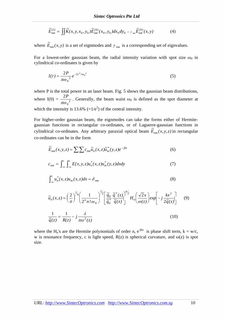
where P is the total power in an laser beam. Fig. 5 shows the gaussian beam distributions,
where I(0) = 2
02
Pπω
. Generally, the beam waist ω0 is defined as the spot diameter at
which the intensity is 13.6% (=1/e2) of the central intensity. For higher-order gaussian beam, the eignmodes can take the forms either of Hermite-gaussian functions in rectangular co-ordinates, or of Laguerre-gaussian functions in cylindrical co-ordinates. Any arbitrary paraxial optical beam ~ ( , )E x y, znm in rectangular co-ordinates can be in the form ~ ( , ) ~ ( , )~ ( )*E x y, z c u x z u y, z enm nm n m
jkz= ∑∑ − (6) c E x y, z u x z u y, z dxdynm n m=
−∞
∞
−∞
∞
∫∫ ( , ) ( , ) ( )* * (7)
u x z u x z dxn m nm
* ( , ) ( , )−∞
∞
∫ = δ (8)
~ ( , )!
~~
~ ( )~( ) ( )
exp ~( )*
*u x z
nqq
q zq z
H xz
j kxq zn n
n
n= ⎛⎝⎜⎞⎠⎟
⎛
⎝⎜
⎞
⎠⎟
⎡
⎣⎢
⎤
⎦⎥
⎛⎝⎜
⎞⎠⎟ −
⎡
⎣⎢
⎤
⎦⎥
2 12
22
14
0
12
0
0
2 2
π ω ω (9)
1 12~( ) ( ) ( )q z R z
jz
= −λ
πω (10)
where the Hn's are the Hermite polynomials of order n, e-jkz is phase shift term, k = w/c, w is resonance frequency, c is light speed, R(z) is spherical curvature, and ω(z) is spot size.
Sintec Optronics Pte Ltd
URL: http://www.SintecOptronics.com http://www.SintecOptronics.com.sg 11
0
0.1
0.2
0.3
0.4
0.5
0.6
0.7
0.8
0.9
1
-2 -1.5 -1 -0.5 0 0.5 1 1.5 2r/w
I(r)/I
(0)
(1, 0.135)
0
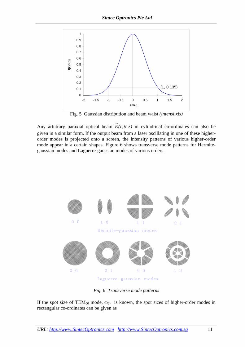
Fig. 5 Gaussian distribution and beam waist (intensi.xls) Any arbitrary paraxial optical beam ~( , , )E r zθ in cylindrical co-ordinates can also be given in a similar form. If the output beam from a laser oscillating in one of these higher-order modes is projected onto a screen, the intensity patterns of various higher-order mode appear in a certain shapes. Figure 6 shows transverse mode patterns for Hermite-gaussian modes and Laguerre-gaussian modes of various orders.
Fig. 6 Transverse mode patterns If the spot size of TEM00 mode, ω0, is known, the spot sizes of higher-order modes in rectangular co-ordinates can be given as

Sintec Optronics Pte Ltd
URL: http://www.SintecOptronics.com http://www.SintecOptronics.com.sg 12
ω ωm m= +2 1 0 (11) and ω ωn n= +2 1 0 (12) where m and n are the null numbers of x and y axles of modes. The spot sizes of higher-order modes in cylindrical co-ordinates are given in Table 2. Table 2 Spot sizes for high-order modes in cylindrical co-ordinates
Mode TEM00 TEM10 TEM20 TEM01 TEM11 TEM21 Spot size ω0 1.50ω0 1.77ω0 1.92ω0 2.21ω0 2.38ω0
It is noted that the practical laser beams often behave in a combination of various modes, except special resonators or other ways used to obtain TEM00 mode. 4.2 CO2 lasers The first CO2 laser operated at the wavelength of 10.6μm in 1964. Because it is one of the most efficient lasers, with 10% conversion efficiency for commercial models, it is widely used in laser cutting, welding, drilling, and surface treatment. It is currently the most powerful material processing laser with commercial laser being offered up to 45 kW. 1. Principle of Operation CO2 laser is a molecular laser. The key lasing material is carbon dioxide molecule. It can take on various energy states depending on the form of vibration or rotation. The basic energy network possible with carbon dioxide is shown in Figure 7. The gas mixture in a carbon dioxide laser is subject to an electric discharge causing the low pressure gas (usually around 30-50 torr) to form a plasma. In the plasma, the molecules take up various excited states as expected from the Boltzmann distribution. Some will be in the upper state (00o1) which represents an asymmetric oscillation mode. By chance this molecule may lose its energy by collision with the walls of the cavity or by spontaneous emission. Through spontaneous emission the state falls to the symmetric oscillation mode (10o0) and a photon of light of wavelength 10.6 μm is emitted travelling in any direction by chance. One of these photons, again by chance, will be travelling down the optics axis of the cavity and will start oscillating between the resonator mirrors.

Sintec Optronics Pte Ltd
URL: http://www.SintecOptronics.com http://www.SintecOptronics.com.sg 13
Fig. 7 Simplified energy-level diagram of the CO2 molecule
In general, the working material in a CO2 laser is a mixture of CO2, He, and N2. N2 plays the role as a buffer gas, and its molecules resonantly transfer the excitation energy to CO2 molecules. Because the relaxation of the level (0110) is the bottleneck, He plays the role as a heat sink to transfer the energy of the level (0110) to He atoms. 2. Types of CO2 lasers The way the waste heat is rejected (or gas cooling method) has a large influence on the laser system design. In principle, it can be performed by two possible methods. The first method is based on the automatic process of natural diffusion of the heated gas to the tube wall, which is the operating principle of the sealed, and slow axial flow lasers. The second method is based on the gas forced convection, which is the operating principle of the fast flow lasers. In general, there are 5 major types of CO2 lasers: - sealed or no-flow - slow axial flow - fast axial flow - fast transverse flow - transverse excited atmosphere (TEA) The sealed or no flow CO2 laser is often used in beam deflected laser marking. Its discharge tube is completely sealed-off. The laser beam quality is excellent. It is very easy to maintain as in most cases the whole discharge tube is replaced with a new one and the used one is sent back for gas-refill. There is no need for a separate gas supply system. Only a fewer connections to the laser head are needed. It is therefore compact and light. However, its output power is low (generally less that 200 W). The TEA CO2 laser is often used in mask marking. It operates in pulsed mode only. The gas flow is low and the gas pressure is high. The excitation voltage is around tens thousand volts. The laser beam energy distribution is uniform over a relatively large area. Its peak power is very high up to 1012 W as its pulse duration is very small. However it is very difficult to focus its laser beam to a small spot due to multimode operation. 3. Pumping power supply In general, there are three key types of pumping power supplies for CW CO2 lasers, i.e. DC, HF and RF. The DC power supply is simple in design. The current in HF power supplies alternate at a frequency between 20 to 50 kHz. HF power supplies are compact in size and efficiency is higher compared to DC power supplies. The current in RF power supplies alternates at a frequency between 2 to 100 MHz. The voltage and the efficiency are lower compared to DC power supplies. 4.3 Nd:YAG lasers

Sintec Optronics Pte Ltd
URL: http://www.SintecOptronics.com http://www.SintecOptronics.com.sg 14
The most practical solid state laser is the YAG laser, which has a high thermal conductivity ten times that of glass, and emits at a wavelength of 1064nm. YAG is an acronym for yttrium-aluminium-garnet (Y3Al5O12), a crystalline manmade substance. A typical YAG laser rod is a cylinder of 50 to 150 mm long and 4 to 10 mm diameter. The YAG rod is not pure. It has 2% of a rare earth element called neodymium uniformly distributed throughout the YAG. Such a neodymium-doped YAG is preferred to as the Nd:YAG. 1. Principle of operation Figure 8 shows the energy-level diagram of a Nd:YAG laser. Lasing is dependent on the rapid transitions from the lower lasing level to the ground state by radiationless transition. When the rod temperature is low, these transitions will occur at a high rate. Hence, lasing efficiency depends mainly on cooling efficiency. Higher output powers can be achieved by having lower operating temperature. This explains why cooling systems are generally operated at temperatures just above the threshold of this effect.
Fig. 8 Energy level system of Nd:YAG laser
In the laser pumping cavity, Nd:YAG crystals are excited by absorbing light from a krypton flash lamp. The crystal absorbs light energy in two 730 - 760 nm and 790 - 820 nm pumping bands which are provided by the krypton lamp. This causes the molecules in the crystal to excite to the E4 pump band shown. The molecules radiate heat in the E4 to E3 transition and the E2 to E1 transition. Subsequently, this heat has to be removed by cooling the crystal rod. 2. Laser pumping cavity One of the most important elements in solid state lasers is pumping cavity. It, besides providing good coupling between the pumping source and the absorbing active material, is also responsible for the pump density distribution in the laser element which influences the uniformity, divergence, and optical distortion of the output beam. Depending on the shape of the active material and the type of pumping source used, pumping geometries can be broadly divided into systems in which the active material is side-pumped, end-pumped, or face-pumped. Fig. 9 shows some of the typical pumping cavities.

Sintec Optronics Pte Ltd
URL: http://www.SintecOptronics.com http://www.SintecOptronics.com.sg 15
Fig. 9 Typical pumping cavities
(a) Single ellipse (b) Double ellipse (c) Circular cylinder (d) Close-wrap
Among the pumping cavities, the elliptical cavities have been most extensively discussed in the development of solid state lasers. In this configuration, a linear lamp and a laser rod, possibly with different radii, are placed at the foci of an elliptical cylinder, as shown in Fig. 9 (a). 3. Laser material The laser material is shaped into a cylindrical rod whose ends are round and polished to be plane parallel. When the rod is placed between two mirrors facing each other, and is strongly irradiated by an intense light source around it, laser is emitted. To minimise cooling problems, YAG rods with smaller diameter are usually used. The rod ends are usually anti-reflection coated for the Nd:YAG wavelength of 1064 nm. The rod ends are held in place and sealed by O-rings recessed in the ends of the rod holders to protect them from the pump lamp light. 4. Cooling system The cooling system is one of the most critical sub-system in a laser. The section of Nd:YAG rod, flashlamp, and pump cavity is cooled with deionised water. This is done by using a water pump in the separately provided cooling unit. The Nd:YAG rod is mounted in a glass tube and the flashlamp is mounted in a water jacket; thus enabling them to be cooled effectively at a high flow velocity. 4.4 Excimer lasers 1. Introduction Excimer lasers were first demonstrated in 1975, more than a decade after most of the other common types of lasers. Despite this fact the technology of excimer lasers has already developed sufficiently. Commercial lasers with output powers of up to a few hundreds of watts are now available and are being incorporated into industrial
Sintec Optronics Pte Ltd
URL: http://www.SintecOptronics.com http://www.SintecOptronics.com.sg 16
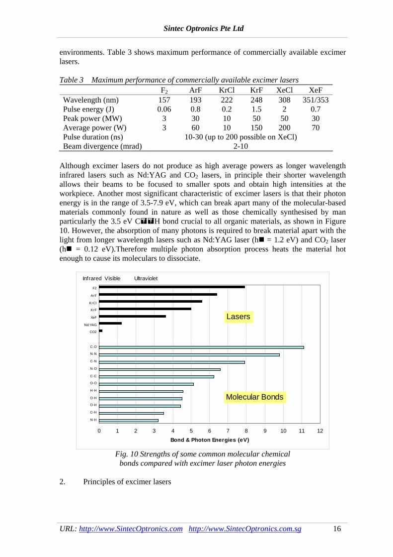
environments. Table 3 shows maximum performance of commercially available excimer lasers. Table 3 Maximum performance of commercially available excimer lasers F2 ArF KrCl KrF XeCl XeF Wavelength (nm) 157 193 222 248 308 351/353Pulse energy (J) 0.06 0.8 0.2 1.5 2 0.7 Peak power (MW) 3 30 10 50 50 30 Average power (W) 3 60 10 150 200 70 Pulse duration (ns) 10-30 (up to 200 possible on XeCl) Beam divergence (mrad) 2-10
Although excimer lasers do not produce as high average powers as longer wavelength infrared lasers such as Nd:YAG and CO2 lasers, in principle their shorter wavelength allows their beams to be focused to smaller spots and obtain high intensities at the workpiece. Another most significant characteristic of excimer lasers is that their photon energy is in the range of 3.5-7.9 eV, which can break apart many of the molecular-based materials commonly found in nature as well as those chemically synthesised by man particularly the 3.5 eV C H bond crucial to all organic materials, as shown in Figure 10. However, the absorption of many photons is required to break material apart with the light from longer wavelength lasers such as Nd:YAG laser (h = 1.2 eV) and CO2 laser (h = 0.12 eV).Therefore multiple photon absorption process heats the material hot enough to cause its moleculars to dissociate.
0 1 2 3 4 5 6 7 8 9 10 11 12
N-H
C-H
O-H
O-H
H-H
O-O
C-C
N-O
C-N
N-N
C-O
CO2
Nd:YAG
XeF
KrF
KrCl
ArF
F2
Bond & Photon Energies (eV)
Infrared Visible Ultraviolet
Lasers
Molecular Bonds
Fig. 10 Strengths of some common molecular chemical
bonds compared with excimer laser photon energies 2. Principles of excimer lasers
Sintec Optronics Pte Ltd
URL: http://www.SintecOptronics.com http://www.SintecOptronics.com.sg 17
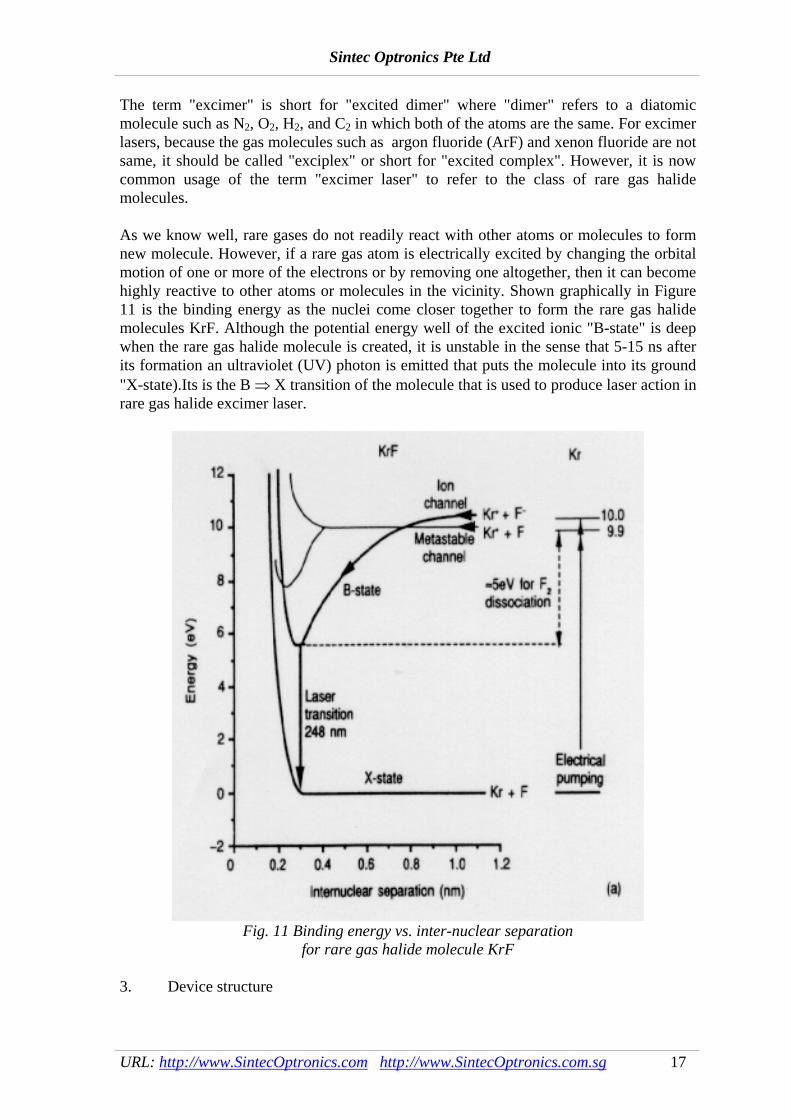
The term "excimer" is short for "excited dimer" where "dimer" refers to a diatomic molecule such as N2, O2, H2, and C2 in which both of the atoms are the same. For excimer lasers, because the gas molecules such as argon fluoride (ArF) and xenon fluoride are not same, it should be called "exciplex" or short for "excited complex". However, it is now common usage of the term "excimer laser" to refer to the class of rare gas halide molecules. As we know well, rare gases do not readily react with other atoms or molecules to form new molecule. However, if a rare gas atom is electrically excited by changing the orbital motion of one or more of the electrons or by removing one altogether, then it can become highly reactive to other atoms or molecules in the vicinity. Shown graphically in Figure 11 is the binding energy as the nuclei come closer together to form the rare gas halide molecules KrF. Although the potential energy well of the excited ionic "B-state" is deep when the rare gas halide molecule is created, it is unstable in the sense that 5-15 ns after its formation an ultraviolet (UV) photon is emitted that puts the molecule into its ground "X-state).Its is the B ⇒ X transition of the molecule that is used to produce laser action in rare gas halide excimer laser.
Fig. 11 Binding energy vs. inter-nuclear separation
for rare gas halide molecule KrF 3. Device structure
Sintec Optronics Pte Ltd
URL: http://www.SintecOptronics.com http://www.SintecOptronics.com.sg 18
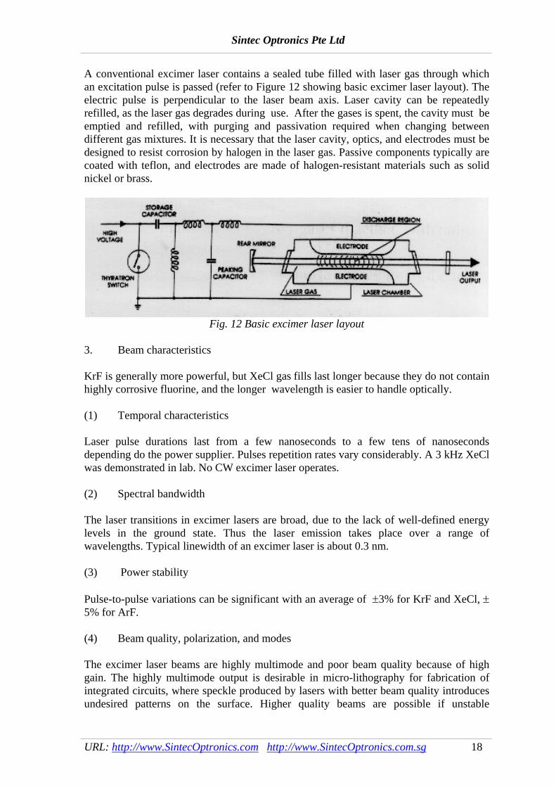
A conventional excimer laser contains a sealed tube filled with laser gas through which an excitation pulse is passed (refer to Figure 12 showing basic excimer laser layout). The electric pulse is perpendicular to the laser beam axis. Laser cavity can be repeatedly refilled, as the laser gas degrades during use. After the gases is spent, the cavity must be emptied and refilled, with purging and passivation required when changing between different gas mixtures. It is necessary that the laser cavity, optics, and electrodes must be designed to resist corrosion by halogen in the laser gas. Passive components typically are coated with teflon, and electrodes are made of halogen-resistant materials such as solid nickel or brass.
Fig. 12 Basic excimer laser layout
3. Beam characteristics KrF is generally more powerful, but XeCl gas fills last longer because they do not contain highly corrosive fluorine, and the longer wavelength is easier to handle optically. (1) Temporal characteristics Laser pulse durations last from a few nanoseconds to a few tens of nanoseconds depending do the power supplier. Pulses repetition rates vary considerably. A 3 kHz XeCl was demonstrated in lab. No CW excimer laser operates. (2) Spectral bandwidth The laser transitions in excimer lasers are broad, due to the lack of well-defined energy levels in the ground state. Thus the laser emission takes place over a range of wavelengths. Typical linewidth of an excimer laser is about 0.3 nm. (3) Power stability Pulse-to-pulse variations can be significant with an average of ±3% for KrF and XeCl, ± 5% for ArF. (4) Beam quality, polarization, and modes The excimer laser beams are highly multimode and poor beam quality because of high gain. The highly multimode output is desirable in micro-lithography for fabrication of integrated circuits, where speckle produced by lasers with better beam quality introduces undesired patterns on the surface. Higher quality beams are possible if unstable
Sintec Optronics Pte Ltd
URL: http://www.SintecOptronics.com http://www.SintecOptronics.com.sg 19
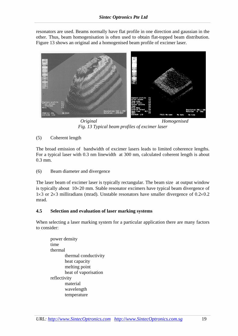
resonators are used. Beams normally have flat profile in one direction and gaussian in the other. Thus, beam homogenisation is often used to obtain flat-topped beam distribution. Figure 13 shows an original and a homogenised beam profile of excimer laser.
Original Homogenised
Fig. 13 Typical beam profiles of excimer laser (5) Coherent length The broad emission of bandwidth of excimer lasers leads to limited coherence lengths. For a typical laser with 0.3 nm linewidth at 300 nm, calculated coherent length is about 0.3 mm. (6) Beam diameter and divergence The laser beam of excimer laser is typically rectangular. The beam size at output window is typically about 10×20 mm. Stable resonator excimers have typical beam divergence of 1×3 or 2×3 milliradians (mrad). Unstable resonators have smaller divergence of 0.2×0.2 mrad.
4.5 Selection and evaluation of laser marking systems When selecting a laser marking system for a particular application there are many factors to consider: power density time thermal thermal conductivity heat capacity melting point heat of vaporisation reflectivity material wavelength temperature

Sintec Optronics Pte Ltd
URL: http://www.SintecOptronics.com http://www.SintecOptronics.com.sg 20
Power density is determined by the amount of (peak) power generated by the laser divided by the area of focused beam. Wavelength, beam divergence and quality of optics become important factors in determining how small a beam can be produced. The amount of time the laser power is focused onto the material also has impact on the ease of marking and depth of penetration. Sometimes, the pulse duration is a key factor in determining which laser can be used. Reflectivity or absorptivity is effected by the type of material, surface condition (i.e. smooth or rough, polish or oxidised), wavelength and surface temperature. In general, metals absorb a greater percentage of Nd:YAG laser energy than that of carbon dioxide laser energy. On the other hand, white paper and most transparent materials absorb a great amount of carbon dioxide laser energy. Some materials such as silicon absorb the same percentage of energy from either laser. After considering above factors, the following step is to evaluate available laser marking systems in the market for the application. The following factors shall be focused on in evaluating the system: laser specifications optical delivery systems control system and software ease of operation manufacturer's performance record price The laser specifications of different types of lasers are different. For CW lasers, the major specifications should include wavelength, average laser power, power stability, beam quality factors (beam spot size, M2, divergence angle, or beam parameter product) and Q-switch element performance (maximum pulse repetition rate, minimum pulse duration, laser peak power). For pulsed lasers, the specifications should include wavelength, average laser power, maximum peak power, maximum energy per pulse, pulse repetition rate, pulse duration, pulse-to-pulse stability, and beam quality factors (beam spot size, M2, divergence angle, or beam parameter product). There are many types of optical delivery systems. For mask marking systems, the systems may include beam expander, homogeniser, CCD camera and monitor or/and microscope, and project lens. The project lens, together with the beam size entering it, determines how big a mark can be obtained per pulse. It and output laser energy/peak power also determine the energy/power density on the workpiece. For beam deflected marking system, the system may include beam expander, CCD camera and monitor or/and microscope, scanner, fibber optics, and f-θ lens. The f-θ lens is very important in determining focused spot size, marking field, minimum marked-line width and power density on the workpiece. The scanner together with the marking software determines the scanning speed. Control systems and software are very different for different laser marking systems. The control system may include feeding of workpiece, stage, control of beam on/off, and interfaces among computer, laser generator, stage, and protection/alarm systems. The

Sintec Optronics Pte Ltd
URL: http://www.SintecOptronics.com http://www.SintecOptronics.com.sg 21
laser marking software also include facilities for controlling other external devices such as work handlers and transport mechanisms as well as interfaces to external triggers for "marking on the fly" applications. The marking software should be easy to implement in a user's system and to program conveniently. It is more compatible to commercially available software in the market. The marking software must generate the required drive and control signals for not only the motion and speed of the marking head but also the laser power (via D/A card). 5. Major components & calculation in laser marking 5.1 Q-switch element The acousto-optical Q-switch often used in the laser marking makes use of mutual interaction between an ultrasonic wave and a light beam in a scattering medium. The light beam that enters in a direction forming a Bragg angle to the wave surface of the acoustic wave in the scattering medium is diffracted in accordance with periodic changes in the diffraction rate produced by the acoustic wave. The situation is briefly explained in Fig. 14. First of all, an RF signal is impressed to the transducer adhered to the melten quartz and thickness extensional vibration is produced. Ultrasonic shear waves are caused to advance in the melten quartz by this vibration, and phase grating formed by acoustic waves is produced. The laser beam is diffracted when it satisfies the Bragg angle with respect to this phase grating, and is separated in space from the incident light.
Fig. 14 Principle of A-O Q-switch
If the laser optical resonator is constructed against 0-dimensional diffracted light (undiffracted light), the diffracted light deviates from the laser optical resonator axis when a RF signal is impressed. As a result, loss occurs in the laser optical resonator and laser oscillation is suppressed. To make use of this phenomenon, an RF signal is impressed for a certain length of time only (status of low Q-value) to suspend laser oscillation. In the mean time, the population inversion of the Nd:YAG rod is accumulated by continuous pumping. When the RF signal is reduced to zero (status of high Q-value) and the loss to the laser optical resonator is removed, the accumulated energy is activated as laser oscillation in a pulse form within an extremely short length of time. They are Q-switch pulses.

Sintec Optronics Pte Ltd
URL: http://www.SintecOptronics.com http://www.SintecOptronics.com.sg 22
This situation is briefly explained in Fig. 15. When an RF signal is subjected to pulse modulation, it is possible to periodically take out a Q-switch pulse. When the period of Q-switch pulses becomes shorter than the life (about 200 μs) of the higher order of the Nd:YAG rod, however, the population inversion decreases and the peak value of Q-switch pulses decreases.
Fig. 15 Laser oscillation output of a Q-switch laser 5.2 Beam expander The most common type of beam expander is derived from the Galilean telescope which usually has one negative input lens and one positive output lens, as shown in Fig. 16. The input lens presents a virtual beam focus at the output. For low expansion ratios (1.3-20×), the Galilean telescope is most often employed due to its simplicity, small package size, and low cost.
Fig. 16 Diagram of a beam expander

Sintec Optronics Pte Ltd
URL: http://www.SintecOptronics.com http://www.SintecOptronics.com.sg 23
As shown in Fig. 16, the lens M3 focuses the laser beam from the laser generator onto the front focus plane and the new beam waist ω′0 and divergence angle θ′ can be represented as
ωλ
πω03′ =
fl( )
(13)
and
′ =′
θ λπω2
0
(14)
ω ω λπω
( )l l= +
⎛⎝⎜
⎞⎠⎟0
02
2
1 (15)
where ω(l) is the radius of the beam entering the lens M3, l is the distance between the lens M3 and the beam waist ω0 from the laser generator, and f3 is the focal length of the lens M3. Since ω0′ just lies on the back focus plane of the lens M4 with a longer focal length, f4, the Gaussian beam with a beam waist ω′0 will be collimated by the beam expander. The collimation ratio of the beam expander for a Gaussian beam is as follows
T T l=
′′= +
⎛⎝⎜
⎞⎠⎟
θθ
λπω1
02
2
1 (16)
where T1 = f4/f3. The beam waist ω″0 and divergence angle θ″ after the beam expander are
ω λ
πω0
0
4″ =
′f (17)
and
′′ =θ θT
(18)
Substituting Equation (13) into Equation (17), the following expression can be obtained ω ω0 1
″ = T l( ) (19) From Equations (16)-(19), it is concluded that the beam expansion ratio and the collimation ratio for a Gaussian beam depend not only on the specifications of the beam expander, but also on the laser beam parameters as well as the positions of the optical lenses. 5.3 F-θ lens

Sintec Optronics Pte Ltd
URL: http://www.SintecOptronics.com http://www.SintecOptronics.com.sg 24
Off axis deflection through a focusing lens system will, in general, form aberrated images in a curved plane as opposed to a more desirable flat surface. A flat field scanning lens is a specialised lens system in which the focal plane of a defected laser beam is a flat surface. In the absence of distortion, the position of the focused spot is dependent on the product of the focal length (F) and the tangent of the deflection angle (θ). When the lens is designed with built-in barrel distortion, the position of the focused spot can then be made dependent on the product of F and θ, thereby simplifying position algorithms. Lenses designed in this way are called F-theta lenses. The scanning lens in laser marking is F-theta lens because line length marked by laser beam is proportional to the angles rotated by the galvanometers. Fig. 17 is a diagram of the standard parameters used for describing and specifying lenses. Two parameters are very important in selecting the scanning lens, scan field diameter and spot size. The scan field diameter determines many of the overall lens specifications. It along with the focal length defines the deflection angle required, since the focus position is proportional to the product of F×θ. The spot size will be most affected by the input laser beam diameter, divergence of the laser source, and the effective focal length of the lens system. For a diffraction limited lens coupled with a Gaussian source, the 1/e2 spot size can be expressed as S = 1.27λ×EFL/A where EFL is the effective focal length of the lens, A is the entrance pupil diameter. In general, the bigger the scan field diameter, the longer the focal length and the bigger the spot size.
Fig. 17 Diagram specifying scan lens
FWD: front working distance, BWD: back working distance, A: entrance pupil diameter, θ: deflection angle
5.4 Beam homogeniser Although there are many homogenisation methods such as cylindrical lens arrays, kaleidoscopes, diffuser plates, mirrors or fibres at present, the simplest way to homogenise the beam is to aperture it down in size, but this causes losses of major of the beam energy, and so it proves an inefficient method. As an example, using multi-prism lenslets as a homogeniser is described in details. Latest-generation homogenisers show transmissions more than 90%. The principle is explained by a bi-prism shown in Figure 18 (a). The bi-prism splits the beam, inverts the two halves and then overlaps them to

Sintec Optronics Pte Ltd
URL: http://www.SintecOptronics.com http://www.SintecOptronics.com.sg 25
produce a more uniform profile. Such a system can have throughputs of 90% and can produce uniformities of better than ±4% over 90% of the beam area. In actual applications, multi-prisms are often used instead of the bi-prisms. The homogenisation system is schematically shown in Figure 18 (b). Lenslets LV1 and LV2 expand the beam to make it roughly square in order to fill the entrance aperture of the homogeniser. Lens arrays A1, A2 and the output focusing lens form the homogeniser. A1 consists of 36 lenslets and hence breaks the beam up into 36 separate beamlets each of which is focused before expanding to intercept the corresponding lenslet in Array 2. The output focusing lens deviates the principal ray from each lenslet to cross the optic axis at its focal plane at which the mask plane is situated. Hence each expanding beamlet from A2 is caused to overlap at the mask plane to give a beam of uniformity. An important property of the homogeniser is that the first array is separated from the second array by the focal length of the lenslets in the second array. Because of this, each lenslet in the first array is imaged (by A2 and FS) onto the mask plane to give a profile with sharp edges. The output of such a homogeniser used with the excimer laser is shown in Figure 13. It is clear the energy distribution has a good uniformity.
(a) Principle of bi-prism- (b) Layout of the homogeniser based homogeniser
Fig. 18 Laser beam homogeniser 6. Laser marking mechanism and quality characteristics Marking contrast can be achieved by surface material removal or color change. When infrared lasers are used, marking contrast relies on thermal effects. When UV lasers, such as excimer lasers are used, marking contrast can be achieved through a photo-chemical transformation, i.e., color change. The process is non-thermal and thus has its unique markets for applications. 6.1 Surface material removal When a laser beam is focused on the surface of a target material, many phenomena may occur as shown in Fig. 19.
Sintec Optronics Pte Ltd
URL: http://www.SintecOptronics.com http://www.SintecOptronics.com.sg 26
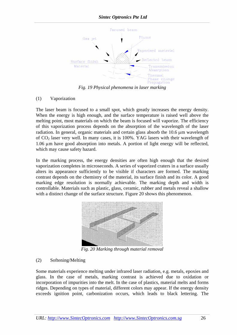
Fig. 19 Physical phenomena in laser marking
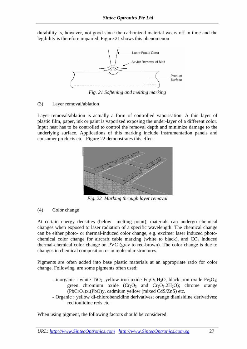
(1) Vaporization The laser beam is focused to a small spot, which greatly increases the energy density. When the energy is high enough, and the surface temperature is raised well above the melting point, most materials on which the beam is focused will vaporize. The efficiency of this vaporization process depends on the absorption of the wavelength of the laser radiation. In general, organic materials and certain glass absorb the 10.6 μm wavelength of CO2 laser very well. In many cases, it is 100%. YAG lasers with their wavelength of 1.06 μm have good absorption into metals. A portion of light energy will be reflected, which may cause safety hazard. In the marking process, the energy densities are often high enough that the desired vaporization completes in microseconds. A series of vaporized craters in a surface usually alters its appearance sufficiently to be visible if characters are formed. The marking contrast depends on the chemistry of the material, its surface finish and its color. A good marking edge resolution is normally achievable. The marking depth and width is controllable. Materials such as plastic, glass, ceramic, rubber and metals reveal a shallow with a distinct change of the surface structure. Figure 20 shows this phenomenon.
Fig. 20 Marking through material removal
(2) Softening/Melting Some materials experience melting under infrared laser radiation, e.g. metals, epoxies and glass. In the case of metals, marking contrast is achieved due to oxidation or incorporation of impurities into the melt. In the case of plastics, material melts and forms ridges. Depending on types of material, different colors may appear. If the energy density exceeds ignition point, carbonization occurs, which leads to black lettering. The
Sintec Optronics Pte Ltd
URL: http://www.SintecOptronics.com http://www.SintecOptronics.com.sg 27
durability is, however, not good since the carbonized material wears off in time and the legibility is therefore impaired. Figure 21 shows this phenomenon
Fig. 21 Softening and melting marking
(3) Layer removal/ablation Layer removal/ablation is actually a form of controlled vaporisation. A thin layer of plastic film, paper, ink or paint is vaporized exposing the under-layer of a different color. Input heat has to be controlled to control the removal depth and minimize damage to the underlying surface. Applications of this marking include instrumentation panels and consumer products etc.. Figure 22 demonstrates this effect.
Fig. 22 Marking through layer removal
(4) Color change At certain energy densities (below melting point), materials can undergo chemical changes when exposed to laser radiation of a specific wavelength. The chemical change can be either photo- or thermal-induced color change, e.g. excimer laser induced photo-chemical color change for aircraft cable marking (white to black), and CO2 induced thermal-chemical color change on PVC (gray to red-brown). The color change is due to changes in chemical composition or in molecular structures. Pigments are often added into base plastic materials at an appropriate ratio for color change. Following are some pigments often used:
- inorganic : white TiO2, yellow iron oxide Fe2O3.H2O, black iron oxide Fe3O4; green chromium oxide (Cr2O3 and Cr2O3.2H2O); chrome orange (PbCrO4)x.(PbO)y, cadmium yellow (mixed CdS/ZnS) etc.
- Organic : yellow di-chlorobenzidine derivatives; orange dianisidine derivatives; red toulidine reds etc.
When using pigment, the following factors should be considered:

Sintec Optronics Pte Ltd
URL: http://www.SintecOptronics.com http://www.SintecOptronics.com.sg 28
- selection of pigment with respects to base material (transparency to laser
wavelength) - effects on base material properties - additional process and cost - could the color degrade with time?
Fig. 23 shows the laser marking through colour change.
Fig. 23 Marking through colour change
6.2 Marking Quality Characteristics The quality of a mark assessed by its legibility characteristics such as mark contrast, mark with, mark depth, spattering, and microcracks. The characteristics are usually evaluated using complementary techniques such as optical microscopy, ultrosonics microscopy, electron microscopy, surface roughness measurement, and contrast evaluation devices. The acceptance of level of each of these characteristics generally depends on the manufacturer's requirements. (1) Mark width Mark width refers to the width of the line segment that forms a character. With the mask image marking, the mark width in the characters is essentially determined by the mask geometry and the lens imaging quality. It can be as small as a few micro-meters, which can only be read under a microscope. In beam deflected marking, the line width is mainly determined by the focused beam spot size, which varies between 20 - 100 mm. Other parameters such as scanning speed, power density and material properties also affect the line width. A toolmaker’s microscope or Talysurf surface texture measuring equipment are used for the line width measurement. (2) Marking depth The depth of marking depends on energy density, types of materials and the beam/material interaction time. In mask marking, the vaporization depth is often determined by the thickness of paint or oxidation layer. It is typical of a few microns to several tens of microns. In beam deflected marking, greater depth of penetration into the material can be achieved varying between a few microns to several tens of a millimeter. A further enhancement of the effect on the material can be realized by the supply of gases such as oxygen or compressed air, which assist material removal.

Sintec Optronics Pte Ltd
URL: http://www.SintecOptronics.com http://www.SintecOptronics.com.sg 29
A RANK TAYLOR HOBSON surface analyzer or a laser beam scanning profiler can be used for depth measurement. (3) Mark contrast Marking contrast is the visual difference between the apparent brightness of the marked surface and unmarked surface of a workpiece. An Image Analysis System can be used for the contrast measurement. It comprises a PC, a 2-axis precision table, a CCD camera and monitor. The light source is a tungsten incandescent light bulb. A reference black and white background provides two extreme grey levels as references in computing the mark contrast, hence compensating for the difference in illumination conditions and the variation of the electronic gain in the system. A histogram plot of the average gray level of the mark, the background material, and the black and white backgrounds are obtained. The marking contrast, c , can be defined as a percentage value as:
c =g g
g gbackground mark
white back
−
− (20)
The sharpness or resolution of the marked edges affects the marking contrast. This parameter is particularly important in marking “bar code”, as poor edge sharpness may fail bar code reader. High peak power or power density produces better edge resolution. (4) Scattering Scattering is characterized by the presence of re-solidified droplets of surface material in the marking area. These scattering are undesirable as they distort mark boundary and producing poor line definition. Visual inspection with an optical microscope is often suffice to evaluate the effect. (5) Microcracks Microcracks are created due to thermal stress generated during laser marking. The micro-cracks affects mechanical properties and may induce corrosion in metals. Scanning acoustic microscope and scanning electron microscope can be used for detection and analysis. (6) Continuity When pulsed or Q-switched CW lasers are used, the repetition rate affects the continuity of the marking. Marking speed is another key factor. An optical scope is used to evaluate the effect. 6.3 Process parameters 1. Effects of average, peak power and pulse energy
Sintec Optronics Pte Ltd
URL: http://www.SintecOptronics.com http://www.SintecOptronics.com.sg 30
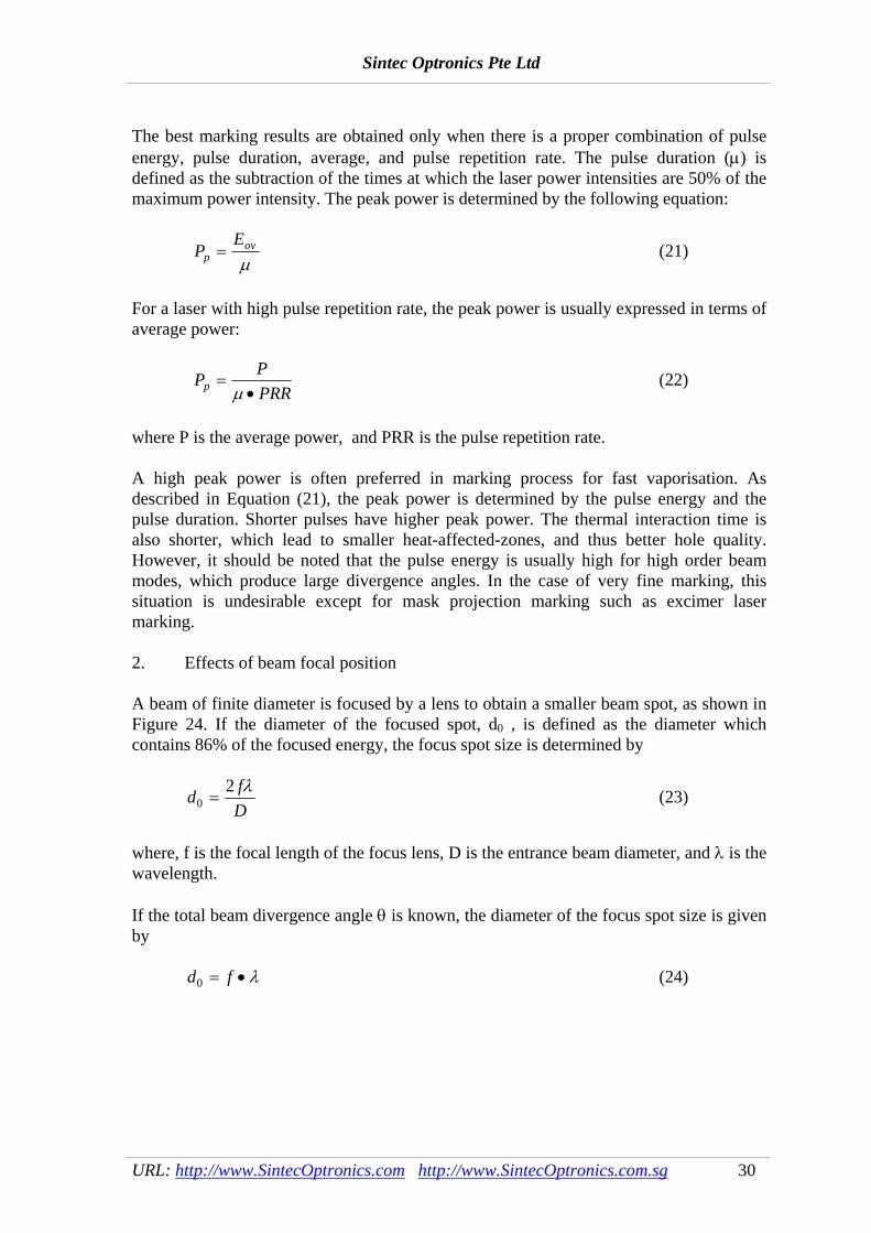
The best marking results are obtained only when there is a proper combination of pulse energy, pulse duration, average, and pulse repetition rate. The pulse duration (μ) is defined as the subtraction of the times at which the laser power intensities are 50% of the maximum power intensity. The peak power is determined by the following equation:
PE
pov=μ
(21)
For a laser with high pulse repetition rate, the peak power is usually expressed in terms of average power:
P PPRRp =
•μ (22)
where P is the average power, and PRR is the pulse repetition rate. A high peak power is often preferred in marking process for fast vaporisation. As described in Equation (21), the peak power is determined by the pulse energy and the pulse duration. Shorter pulses have higher peak power. The thermal interaction time is also shorter, which lead to smaller heat-affected-zones, and thus better hole quality. However, it should be noted that the pulse energy is usually high for high order beam modes, which produce large divergence angles. In the case of very fine marking, this situation is undesirable except for mask projection marking such as excimer laser marking. 2. Effects of beam focal position A beam of finite diameter is focused by a lens to obtain a smaller beam spot, as shown in Figure 24. If the diameter of the focused spot, d0 , is defined as the diameter which contains 86% of the focused energy, the focus spot size is determined by
d fD0
2=
λ (23)
where, f is the focal length of the focus lens, D is the entrance beam diameter, and λ is the wavelength. If the total beam divergence angle θ is known, the diameter of the focus spot size is given by d f0 = • λ (24)

Sintec Optronics Pte Ltd
URL: http://www.SintecOptronics.com http://www.SintecOptronics.com.sg 31
Fig. 24 Focusing of a gaussian beam
As the gaussian beam focuses from a lens down to a waist and then expands, there is a need to define a depth of focus. Normally, it is defined as the distance between the 2 d0 spot size points or 2 times Rayleigh range. It can be written as Δf Z FR= ≈2 2 2πλ (25) or
Δf fD
=2 2θ (26)
where F is the f-number of a focusing lens, which is defined as
F fD
= (27)
It is concluded from Eqs. (23) to (27) that a lens with a longer focal length gives a longer depth of focus and a larger focus spot size than those produced by a lens with a shorter focal length. Thus the focal length of the focus lens should be selected properly according to the marking requirements. 3. Effects of beam mode and spot size Since the order of the beam mode has great effects on both the focused spot size and the depth of focus, the beam mode structure plays an important role in laser materials processing. A laser beam with a higher-order mode structure diverges more rapidly, focuses to a larger spot and has a shorter depth of focus than a TEM00 gaussian beam. In laser marking, it is generally desirable to achieve highest possible speed and therefore the highest possible power density. Thus the lowest order mode is desirable (TEM00 or gaussian mode for stable resonators). However, a low-order mode structure often means a lower conversion efficiency and thus less laser output power. Therefore optimisation is needed for obtaining a good processing quality, proper processing speed, and laser output power. 4. Laser wavelength

Sintec Optronics Pte Ltd
URL: http://www.SintecOptronics.com http://www.SintecOptronics.com.sg 32
Generally, beam energy is much better absorbed by materials at shorter wavelengths. Also, the wavelength determines a theoretical limit on how small a beam can be focused. For a TEM00 laser diffraction limited optics, the focused spot size, s, can be given by s f d= 1 27. ( / )λ (28) where λ is the laser wavelength, f is the lens focal length, and d is the diameter of the beam (entering the lens). It is obvious that the focused spot is proportional to the laser wavelength. The spot size reduces by a factor of two and the focused spot area does by a factor of four when the laser wavelength is converted from 1.06 μm to 0.532 μm. The wavelength also determines the interaction mechanism - thermal or photochemical, as shown in Fig. 10. Reflectivities of a number of metals are a function of wavelengths, as shown in Fig. 25.
Fig. 25 Absorption vs. wavelength
5. Material properties For any material, absorptivity, reflectivity, and transmissivity will satisfy absorptivity + reflectivity + transmissivity =1 In general, metals absorb well of Nd:YAG laser beam energy, while paper and most transparent materials (e.g. polymers and glass) absorb well of CO2 laser energy. Almost all materials absorb well the short wavelengths of excimer laser beams. Surface finish or coating affects absorptivity. Bare metal surface will be difficult to mark by CO2 lasers, but can be easily marked by YAG or excimer lasers. Glass and transparent plastics are not suitable for YAG laser marking. Nearly all materials can be marked by excimer lasers with a shallow depth. 6. System requirements
Sintec Optronics Pte Ltd
URL: http://www.SintecOptronics.com http://www.SintecOptronics.com.sg 33
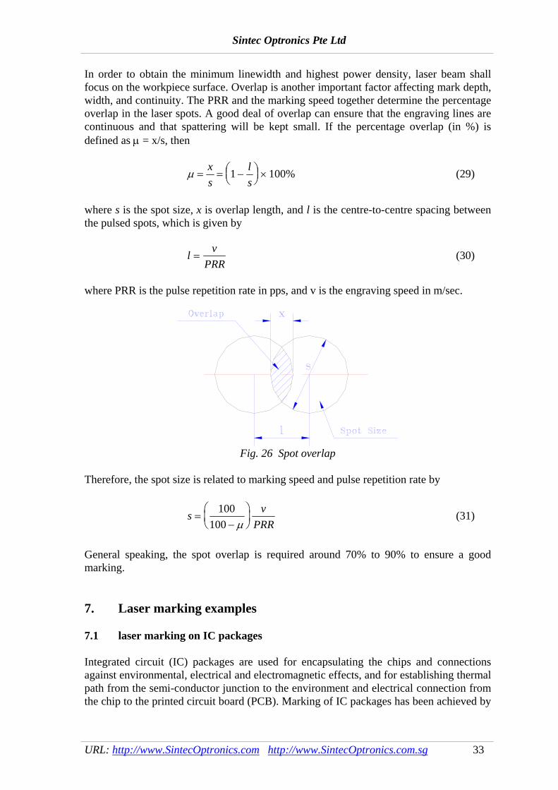
In order to obtain the minimum linewidth and highest power density, laser beam shall focus on the workpiece surface. Overlap is another important factor affecting mark depth, width, and continuity. The PRR and the marking speed together determine the percentage overlap in the laser spots. A good deal of overlap can ensure that the engraving lines are continuous and that spattering will be kept small. If the percentage overlap (in %) is defined as μ = x/s, then
μ = = −⎛⎝⎜
⎞⎠⎟ ×
xs
ls
1 100% (29)
where s is the spot size, x is overlap length, and l is the centre-to-centre spacing between the pulsed spots, which is given by
l vPRR
= (30)
where PRR is the pulse repetition rate in pps, and v is the engraving speed in m/sec.
Fig. 26 Spot overlap
Therefore, the spot size is related to marking speed and pulse repetition rate by
s vPRR
=−
⎛⎝⎜
⎞⎠⎟
100100 μ
(31)
General speaking, the spot overlap is required around 70% to 90% to ensure a good marking. 7. Laser marking examples 7.1 laser marking on IC packages Integrated circuit (IC) packages are used for encapsulating the chips and connections against environmental, electrical and electromagnetic effects, and for establishing thermal path from the semi-conductor junction to the environment and electrical connection from the chip to the printed circuit board (PCB). Marking of IC packages has been achieved by

Sintec Optronics Pte Ltd
URL: http://www.SintecOptronics.com http://www.SintecOptronics.com.sg 34
ink printing techniques such as 'Soft-Tough Symbol' or 'Ink-offset Transfer'. However, the ink printing techniques pose several drawbacks:
• cleaning and decreasing prior to the ink print process • curing time for ink to dry • non-permanent mark • chemicals disposal with environmental concerns • untidy working environment • maintenance cost is high • high inventory
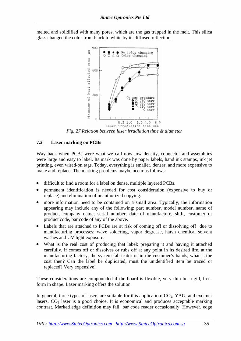
Laser marking offers good potential to replace the ink printing techniques. It is achieved usually by either beam deflected marking with Q-switched Nd:YAG lasers or mask marking with pulsed TEA CO2, Nd:YAG or excimer lasers. In mask marking of IC packages, the marking area is determined by the output power of the laser, the cross-section of the beam and the properties of the material being marked. Marked area of 75 mm2 at 10 J/pulse with pulse duration of about 0.69 ms has been reported for uncoated plastic packages. For the coated plastic packages (e.g. marker ink or varnish), the marked area can reach 600 mm2 per pulse with pulse energy ranging from 0.1 J to 0.75 J and a pulse repetition frequency of 30 Hz. For mask marking, a minimum character height of about 0.5 mm has been reported. An advantage of mask marking is that large quantities of packages can be marked at relatively high speed with high repeatability, provided that the marked message stays the same. Typical marking rate of about 20 packages per second or about 120 million packages per year on a single-shift basis has been reported. Marking “on the fly” is possible due to the short pulse width (tens of nanoseconds) in the mask marking mode, where components are continuously moving underneath the beam. Mask is often made of metals (stainless steel or copper). A mask inventory is necessary as spare parts or masks of different patterns. In beam deflected marking of IC packages, CW Q-switched Nd:YAG laser is most commonly used at present. This is because some color change is achieved and the thermal effect is less compared to the use of CO2 lasers. Marking contrast is generally poor with no or little colour change. Surface roughness or grooves are utilized for distinction. It was reported by researchers in Tokyo Institute of Technology that both the laser beam interaction time and the atmosphere have significant influence on the change of color. - color change started after a period of beam/material interaction - color change occurred in oxygen atmosphere, but not in argon atmosphere. The experimental results showing the relationship between laser radiation time and area of white portion is shown in Fig. 27. One possible explanation given is that carbon black is oxidized and vaporized in oxygen-rich atmosphere. Whereas, silica glass powder was
Sintec Optronics Pte Ltd
URL: http://www.SintecOptronics.com http://www.SintecOptronics.com.sg 35
melted and solidified with many pores, which are the gas trapped in the melt. This silica glass changed the color from black to white by its diffused reflection.
Fig. 27 Relation between laser irradiation time & diameter
7.2 Laser marking on PCBs Way back when PCBs were what we call now low density, connector and assemblies were large and easy to label. Its mark was done by paper labels, hand ink stamps, ink jet printing, even wired-on tags. Today, everything is smaller, denser, and more expensive to make and replace. The marking problems maybe occur as follows: • difficult to find a room for a label on dense, multiple layered PCBs. • permanent identification is needed for cost consideration (expensive to buy or
replace) and elimination of unauthorized copying. • more information need to be contained on a small area. Typically, the information
appearing may include any of the following: part number, model number, name of product, company name, serial number, date of manufacture, shift, customer or product code, bar code of any of the above.
• Labels that are attached to PCBs are at risk of coming off or dissolving off due to manufacturing processes: wave soldering, vapor degrease, harsh chemical solvent washes and UV light exposure.
• What is the real cost of producing that label: preparing it and having it attached carefully, if comes off or dissolves or rubs off at any point in its desired life, at the manufacturing factory, the system fabricator or in the customer’s hands, what is the cost then? Can the label be duplicated, must the unidentified item be traced or replaced? Very expensive!
These considerations are compounded if the board is flexible, very thin but rigid, free-form in shape. Laser marking offers the solution. In general, three types of lasers are suitable for this application: CO2, YAG, and excimer lasers. CO2 laser is a good choice. It is economical and produces acceptable marking contrast. Marked edge definition may fail bar code reader occasionally. However, edge

Sintec Optronics Pte Ltd
URL: http://www.SintecOptronics.com http://www.SintecOptronics.com.sg 36
definition for YAG laser marking is better. It is able to mark very small letters, but is more expensive. Excimer laser marking is non-thermal marking. It has excellent marked edge definition and accurate depth control. It is able to mark very small letters, but excimer laser marking is the most expensive among the three lasers. PCBs are made of epoxy FR4, marking directly on the epoxy may cause craters and some surface charring, and therefore marks are not uniform and unsatisfactory (barcode marks may not read due to poor edge resolution). The coatings used on PCBs such as dark shaded photo resist and conformal coating, promote good marks. The marks appear as a pale yellow against a deep green. Another popular approach is to coat a patch or an area on a PCB with an epoxy ink that has been formulated to survive harsh solvents and thermal shock after curing. Such epoxy inks are either IR or UV cured. The ink is best if it is chromium or TiO2 based (white). Laser marks will appear black at a specific wavelength or simply exposing the deep green under-layer. Dot matrix marking or galvanometer type of beam scanning are well suited. 7.3 Laser marking of polymers As plastic items such as bottles, containers, and automobile parts become more cost effective, the demand to laser mark these parts also increases. However, many common polymers such as polyethylene, polypropylene and polycarbonates do not mark well in their pure states. Polymers are rarely seen in their pure state, however, because a variety of additives such as inorganic fillers, flame retardants, UV inhibitors, colorants and stabilisers are added. And, based on the analysis given above, additives that increase the optical absorption coefficient of the polymer should improve the marking process simply by increasing the rate of temperature rise. By incorporating additives with high absorption and choosing the appropriate laser wavelength, enhanced markability has been achieved. Organic pigments are often used as colorant for polymers. Because these are strong absorbers of visible light, they usually lasermark well. The polychromatic (both black and white) laser mark exhibits two marking effect depending on the energy density of the frequency-doubled green YAG laser namely: • bleaching of the pigment to allow the underlying polymer colour to shown through; • carbonisation of the polymer. In addition, sensitivity of the material to energy can be modulated pulse to pulse. Inorganic materials such as silica are common additives in polymers used for foodstuff containers. Some inorganic additives that have been used to enhance the laser markability of polymers include mica, carbon black, titanium dioxide, and kaolin. A series of metal-oxide-coated mica additives have recently been shown to allow good laser marks on previously unmarkable polyolefins using CO2 and YAG laser markers. These additives, sold by E Merck under the trade mark names AFFLAIR and LAZER FLAIR, have already been widely used to give a metallic appearance to automobile body paints, and a pearllescent (pear-like) appearance to cosmetic and pharmaceutical bottles. Pearlescence is basically an optical interference effect of white light interacting with the layered

Sintec Optronics Pte Ltd
URL: http://www.SintecOptronics.com http://www.SintecOptronics.com.sg 37
structure of mica platelets near the surface of the polymer. Enhanced marking of the polymer is probably not due to absorption by the mica, but rather due to trapping of the laser light near the surface to cause thermal decomposition of the polymer. 8. References 1. Chen Yihong, Tang Zhonghua, Qiu Junlin, Optical parameters computation for CO2
laser marking system, Laser Technology, Vol. 18, No. 1 (1994), 36-41 (in Chinese) 2. G. A. Shukov and A. Smith, Micromachining with excimer lasers, Lasers &
Optronics, Vol. 7, No. 9 (1988), 75-77 3. David P. Beach, Allen Shotwell, and P. Essue, Applications of Lasers and Laser
Systems, Englewood Cliffs, NJ: Prentice-Hall, 1993 4. S. C. Tam, Y. M. Noor, L. E. N. Lim, and S. Jana, Laser marking of IC packages,
Proceedings of ISLOE'93, 96-103 5. S. Tezuka & M. Yoshikawa, Study on the marking processing of IC packages by
YAG laser, Int. J. Japan Soc. Proc. Eng., Vol. 25, No. 4 (1991), 297-299 6. R. T. Crowley, Laser fabrication of photomasks for hybrid circuits, Proc. of SPIE
Vol. 611 Laser Processing of Semiconductors and Hybrids (1986), 18-22 7. J. F. Higgins, Laser marking of passive components, hybrids and semiconductors,
Proc. of SPIE Vol. 611 Laser Processing of Semiconductors and Hybrids (1986), 40-47
8. J. Sercel and U. Sowada, Why excimer lasers excel in marking, Lasers & Optronics, Vol. 7, No. 9 (1988), 69-72
9. G. A. Shukov and A. Smith, Micromachining with excimer lasers, Lasers & Optronics, Vol. 7, No.9 (1988), 75-77
10. S. C. Tam, Yusoff Md. Noor, L. E. N. Lim and S. Jana, Laser marking of IC packages, ISLOE'93 Proceedings, Nov. 1993, 96-103
11. B. H. Klimt, Review of laser marking and engraving, Lasers & Optronics, Vol. 7, No.9 (1988), 61-67
12. H. L. Deng, Laser marking- a feasible industrial laser application, Laser & Infrared, 1986, No. 4, 27-29 (in Chinese)
13. M. Hofmann, F. Breitenfellner, N. Buehler, R. C. Skykes and H. Gugger, High contrast and intact surface-challenge in laser marking of plastics, Proc. of SPIE Vol. 744 Lasers in Motion for Industrial Applications, 156-180
14. S. Tezuka and M. Yoshikawa, Study of the marking processing of IC packages by YAG laser, Int. J. Japan Soc. Prec. Eng., Vol. 25, No.4 (1991), 297-300
14. B. Bernard, Laser marking techniques, Lasers in Material Processing, Los Angeles, U.S., 24-26 Jan. 1983, 48-52
15. A. V. Gress, Laser marking of component parts, Lasers in Material Processing, Los Angeles, U.S., 24-26 Jan. 1983, 54-62
16. T. J. McKee, How lasers mark, ElectroTechnology, Vol. 7, No. 2 (1996), 27-31 17. J. B. Willis, Laser marking-what are the benefits, Proc. 4th Int. Conf. on Lasers in
Manufacturing (1987), 33-40 18. B. Marx, Light tough, Manufacturing Engineer, June 1996, 111-113 19. J. J. Benes, Lasers make their mark in metalworking, American Machinist, July 1996,
93-95 20. C. M. Bosnos, Meeting the challenges of marking ultrathin packages, Asian
Electronics Engineer, July 1996 21. Merck: Iriodin LS for the laser marking of plastics

Sintec Optronics Pte Ltd
URL: http://www.SintecOptronics.com http://www.SintecOptronics.com.sg 38
22. R. L. Stevenson, Industrial strength laser marking: turning photons into dollars, Excel\Control Laser, Inc.
23. W. M. Steen, Laser Material Processing, Springer-Verlag, 1991 24. Make it with lasers, Excimer laser workshop, Exitech Ltd, Oct. 13, 1994 25. T. Hiruma, New development on photonics, Proc. of 1995 International Conference
on Optoelectronics and Lasers (Hangzhou, Oct. 1995), 2-4 26. T. H. Maiman, Optical and microwave-optical experiments in ruby, Physics Review
Letters, Vol. 4, No. 11 (1960), 564-566 27. J. F. Ready, Industrial Applications of Lasers, Academic Press, New York, 1978 28. A. Yariv, Quantum Electronics, 3rd ed. Wiley, New York, 1988 29. O. Svelto, Principles of Lasers, 3rd ed. Plenum Press, New York, 1989 30. J. V. Owen, Lasers on the line, Manufacturing Engineering, Vol. 116, No. 6 (1996),
33-42 31. K. Owen, Laser diodes find their own niche, Photonics Spectra, Vol. 30, No. 1
(1996), 94-95 32. Allister and J. White, Solid state lasers improve bio-imaging applications, Photonics
Spectra, Vol. 30, No. 1 (1996), 100-103 33. J. Tracy, High-power diode lasers serve medical, industrial applications, Photonics
Spectra, Vol. 30, No. 1 (1996), 96-98 34. D. Basting, Excimer laser technology opens doors for industrial innovations,
Photonics Spectra, Vol. 30, No. 1 (1996), 99 35. S. G. Anderson, Review and forecast of laser markets: 1994, Laser Focus World,
Vol. 30, No. 1 (1994), 62-76 36. T. Kilp, Laser marking of plastics, ANTEC'91, 1901-1903 37. J. Miller, Laser marking enhances IC identification, Evaluation Engineering, Jan.
1990, 20-22 38. K. Kuwabara, Nd:YAG laser marker utilising a liquid-crystal-device mask, SPIE
Vol. 1223 Solid State Lasers (1990), 47-53 39. J. H. Scaroni, Laser marking technology, SPIE Vol. 527 Applications of High Power
Lasers (1985), 11-17 40. S. J. Parnas, Indelible coding with lasers: variable information marking on-the-fly,
Surface Mount Technology, Dec. 1989, 20-28 41. R. L. Stevenson, Lasers, The Fabricator, April 1993, 64-67 42. C. Herkt-Maetzky, Investigation on colour change reaction during laser marking of
plastics, Macroomol. Symp. 100 (1995), 57-63 43. G. Graff, Additives make possible laser marking of polyolefin components, Modern
Plastics, April 1996, 24-25 44. D. R. Alexander, Laser marking using organo-metallic films, Optics and Lasers in
Engineering 25 (1996), 55-70 45. K. Sakai, Resin compositions for laser marking, European patent, EP 0572178A1,
1993 46. H. Kato, Resin composition for laser marking, European patent, EP0644234A1, 1994 47. T. Kiyonari, Laser marking method and resin composition for laser marking, US
patent 5063137, 1991 48. F. Herren, Laser marking of ceramic materials, glazes, glass ceramics and glasses,
US patent 5030551, 1991 49. H. Gugger, Laser marking of ceramic materials, glazes, glass ceramics and glasses,
US patent 4769310, 1988