co30a laser marking system - telesistelesis.com/pdf/47823.pdfco30a laser marking system co30a laser...
TRANSCRIPT
CO30A Laser Marking System
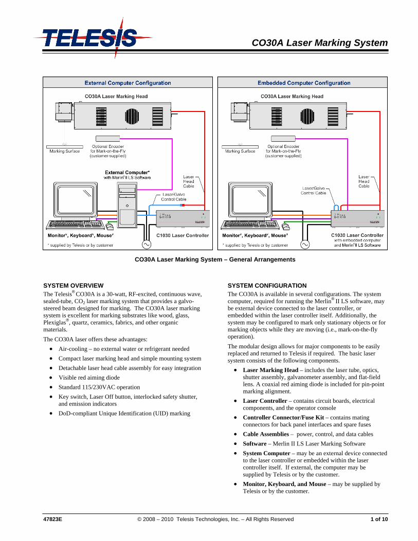
CO30A Laser Marking System – General Arrangements
SYSTEM OVERVIEW The Telesis® CO30A is a 30-watt, RF-excited, continuous wave, sealed-tube, CO2 laser marking system that provides a galvo-steered beam designed for marking. The CO30A laser marking system is excellent for marking substrates like wood, glass, Plexiglas®, quartz, ceramics, fabrics, and other organic materials. The CO30A laser offers these advantages: • Air-cooling – no external water or refrigerant needed • Compact laser marking head and simple mounting system • Detachable laser head cable assembly for easy integration • Visible red aiming diode • Standard 115/230VAC operation • Key switch, Laser Off button, interlocked safety shutter,
and emission indicators • DoD-compliant Unique Identification (UID) marking
SYSTEM CONFIGURATION The CO30A is available in several configurations. The system computer, required for running the Merlin® II LS software, may be external device connected to the laser controller, or embedded within the laser controller itself. Additionally, the system may be configured to mark only stationary objects or for marking objects while they are moving (i.e., mark-on-the-fly operation). The modular design allows for major components to be easily replaced and returned to Telesis if required. The basic laser system consists of the following components. • Laser Marking Head – includes the laser tube, optics,
shutter assembly, galvanometer assembly, and flat-field lens. A coaxial red aiming diode is included for pin-point marking alignment.
• Laser Controller – contains circuit boards, electrical components, and the operator console
• Controller Connector/Fuse Kit – contains mating connectors for back panel interfaces and spare fuses
• Cable Assemblies – power, control, and data cables • Software – Merlin II LS Laser Marking Software • System Computer – may be an external device connected
to the laser controller or embedded within the laser controller itself. If external, the computer may be supplied by Telesis or by the customer.
• Monitor, Keyboard, and Mouse – may be supplied by Telesis or by the customer.
47823E © 2008 – 2010 Telesis Technologies, Inc. – All Rights Reserved 1 of 10
CO30A Laser Marking System
2 of 10 47823E
SYSTEM SPECIFICATIONS Compliance .............................. CDRH Laser Type ............................... RF-excited, continuous wave,
sealed-tube, carbon dioxide laser Wavelength .............................. 10.6 micrometers (µm) CW Average Power ................ 30 watts Long Term Output Power Drift .......................... < ±5% Power Consumption ................ approx. 3.0 amps at 115 VAC Input Power .............................. 115 VAC, single-phase,
15A, 50/60Hz 230 VAC, single-phase, 7.5A, 50/60Hz
Supply Voltage Fluctuation ..... < ±10% with clean ground line Operational Temperature........ 15° to 30°C (59° to 86°F) Recommended Temperature.. 16° to 24°C (61° to 75°F) Ambient Relative Humidity ...... 10% to 90% non-condensing
SYSTEM OPTIONS • External computer (desktop or notebook with powered
cardbus-to-PCI expansion enclosure) to run the Merlin II LS Laser Marking Software
• Embedded computer within laser controller to run Merlin II LS Laser Marking Software
• Remote pushbutton station (start/abort) • Externally-mounted focus-finder diode • Mark-on-the-fly kit to interface with customer-supplied
encoder for marking objects in motion (linear or circular) • I/O options (see Remote Communications for details):
TTL via PCI-DIO24 Board Opto-isolated via Merlin DCIO Module Two-axis Controller
• Manually operated tool post for z-axis adjustment • Programmable tool post for z-axis adjustment (requires
two-axis controller) • Programmable rotary drive fixture for theta-axis
adjustment (requires two-axis controller) • Workstation / Work Area Enclosure • Fume Extraction Systems
SYSTEM SETUP The following procedures are listed for reference only to provide a general overview of the installation process. Refer to the CO30A Installation & Maintenance Manual for complete installation details.
Do not connect any power cable to power source until all system connections are made.
1. All equipment must remain powered down and in the OFF position until mounting and connection are complete.
2. Place the laser controller, monitor, keyboard, mouse, and if applicable, the external system computer, in the desired locations. Locate the laser controller as close as practical to the laser marking head.
3. Ensure sufficient clearance exists on all sides of the laser controller to allow for proper air circulation. Allow sufficient space behind the laser controller to permit proper installation of applicable cables. Refer to the Dimensions & Mounting drawings for details.
4. Place the laser marking head on a suitable mounting surface.
5. Ensure sufficient clearance exists on all sides of the laser marking head to allow for proper air circulation. Allow sufficient space behind the laser marking head to permit proper installation of applicable cables.
6. Mount the laser marking head with three M8-1.25 bolts and lock washers using the factory-tapped mounting holes provided. Refer to the CO30A Dimensions & Mounting drawing for details. Caution: Maximum mounting bolt penetration into
the laser marking head is 7.8 mm (.31 in.). Note: Optionally, three M6 locating pins may be
used at the 0.2362 P6 hole locations for more precise marking head alignment.
7. Connect all cables remaining cables, as applicable.
8. Connect any optional or customer-supplied devices or interface circuits as applicable.
9. Refer to the CO30A Operation Supplement for proper startup procedure. Refer to the Merlin II LS Operating Instructions for complete information on using the system software.

CO30A Laser Marking System
47823E 3 of 10
CO30A Laser Marking Head Dimensions & Mounting Details
C1030 Laser Controller Dimensions & Mounting Details (external computer configuration shown – embedded computer configuration similar)

CO30A Laser Marking System
CO30A LASER MARKING HEAD SAFETY LABELS The following illustration shows the labels and their locations on the CO30A laser marking head. Please familiarize yourself with the laser labels and their locations prior to operating the laser marking system.
4 of 10 47823E
CO30A Laser Marking System
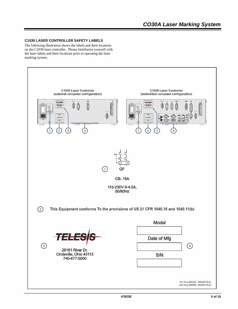
C1030 LASER CONTROLLER SAFETY LABELS The following illustration shows the labels and their locations on the C1030 laser controller. Please familiarize yourself with the laser labels and their locations prior to operating the laser marking system.
47823E 5 of 10
CO30A Laser Marking System
6 of 10 47823E
CO30A LASER MARKING HEAD The laser marking head incorporates the latest technology in sealed-tube, RF-excited, continuous wave, carbon dioxide lasers, providing excellent output power, stability, and reliability in a rugged compact modular package.
Dual-Sensor Shutter Circuit The CO30A laser marking head employs two separate sensors to detect the closed-state of the laser shutter mechanism. The sensor signals can be monitored at the Outputs Connector on the back panel of the laser controller. When the shutter is open, the sensor feedback signals are OFF. When the shutter is closed, the sensor feedback signals are ON.
Visible Red Aiming Diode Laser marking head includes a visible red diode that can be viewed on the work surface without the need for protective safety goggles. The aiming diode provides a safe and convenient aid for laser setup and part programming. Since the red beam is located after the shutter, the aiming beam may be used with the shutter opened or closed. Additionally, the visible red beam may be used with the lasing beam during the marking cycle. Note that protective eyewear must always be worn when the laser is in operation.
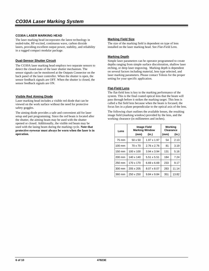
Marking Field Size The size of the marking field is dependent on type of lens installed on the laser marking head. See Flat-Field Lens.
Marking Depth Simple laser parameters can be operator programmed to create depths ranging from simple surface discoloration, shallow laser etching, or deep laser engraving. Marking depth is dependent on several factors including material, lens type selected, and laser marking parameters. Please contact Telesis for the proper setting for your specific application.
Flat-Field Lens The flat-field lens is key to the marking performance of the system. This is the final coated optical lens that the beam will pass through before it strikes the marking target. This lens is called a flat field lens because when the beam is focused, the focus lies in a plane perpendicular to the optical axis of the lens. The following chart outlines the available lenses, the resulting image field (marking window) provided by the lens, and the working clearance (in millimeters and inches).
Lens
Image Field Marking Window
(mm) (in.)
Working Clearance
(mm) (in.)
75 mm 50 x 50 1.97 x 1.97 54 2.13
100 mm 70 x 70 2.76 x 2.76 81 3.19
150 mm 100 x 100 3.94 x 3.94 131 5.16
200 mm 140 x 140 5.51 x 5.51 184 7.24
250 mm 170 x 170 6.69 x 6.69 233 9.17
300 mm 205 x 205 8.07 x 8.07 283 11.14
360 mm 250 x 250 9.84 x 9.84 351 13.82

CO30A Laser Marking System
C1030 LASER CONTROLLER Designed to meet CDRH and IEC 60825-1 standards, the laser controller is remotely connected to the laser marking head by the laser marking head cable assembly. The cable assembly carries power and control signals to the laser marking head. The laser controller provides the electrical control of the laser marking system. The controller connects to the facility electrical supply to provide power to the laser marking system. The laser controller is also the electrical interface between the laser marking software (installed on the system computer) and the laser marking head. It provides buttons and indicators to control and monitor the laser marking process.
Operator (Front) Panel The laser control panel includes the system enable key switch, a soft power on/off button, green power indicator, laser start push button, laser off push button, safety shutter open and close controls, and a laser on (emission) indicator.
C1030 Laser Controller – Front Panel
Connector (Back) Panel for External Computer Usage
The rear panel of the controller provides a power entry module with circuit breaker and connectors for the laser marking head cable and the laser/galvo control cable. It also provides a remote interlock connector and a remote pendant connector. An output connector allows you monitor output signals reporting the status of the shutter, laser emission, and fault conditions.
C1030 Laser Controller Back Panel – External Computer
Connector (Back) Panel with Embedded Computer The rear panel of the controller provides a power entry module with circuit breaker and connectors for the laser marking head cable and the laser/galvo control cable. It also provides a remote interlock connector and a remote pendant connector. An output connector allows you to monitor output signals reporting the status of the shutter, laser emission, and fault conditions. An opto-isolated I/O connector and an I/O cable is provided for connection to the remote I/O devices. Refer to Remote Communications for more information. Connections for the embedded system computer are mounted on a sub-panel. The separate panel allows you to connect a monitor, keyboard and mouse directly to the laser controller. Additional RS-232, Ethernet, and USB ports are provide for other optional connections and usage.
C1030 Laser Controller Back Panel – Embedded Computer
SYSTEM COMPUTER The laser system requires an IBM-compatible computer for running the Merlin II LS Laser Marking Software. The system computer may be an external device connected to the laser controller, or it may be embedded within the controller itself. If supplied by Telesis, the Laser/Galvo Controller board and the Merlin II LS is installed in the system computer prior to shipment and the entire unit is tested as a laser marking system. Warranty for the computer, keyboard, monitor, and peripherals default to the original equipment manufacturer. If the system computer is supplied by anyone other than Telesis it must, at a minimum, meet the following specifications: Operating System..... Windows® 2000, Windows® XP, or
Windows® Vista™ Business Edition Operator Interface .... Telesis Merlin II LS Laser Marking Software Processor ................. Pentium® III with RAM as recommended
per operating system Hard Drive ................ 2 GB Hard Disk Drive External Drives ......... CD-ROM Drive Comm Ports.............. One available RS-232 Serial Port, Two available USB Ports, Two available full-height PCI Slots * Circuit Cards............. Laser/Galvo Controller Board, Video Board Peripherals ............... SVGA Color Monitor, Mouse, Keyboard,
* One additional PCI slot required if system is configured for mark-on-the-fly operation.
If system computer is a notebook, expansion must be used to provide the PCI slots.
47823E 7 of 10

CO30A Laser Marking System
SYSTEM SOFTWARE The powerful Telesis Merlin II LS Laser Marking Software is a Windows® based software package that comes standard with the laser marking system. It is a graphical user interface that makes marking pattern design quick and easy. The WYSIWYG (what-you-see-is-what-you-get) interface provides a to-scale image of the pattern as it is created. Just “click and drag” for immediate adjustment to field size, location, or orientation. The Merlin II LS software includes tools to create and edit text at any angle, arc text, rectangles, circles, ellipses, and lines. Multiple fields may be grouped and saved as a block to form a logo. Existing DXF files can also be imported for marking. Non-printable fields can be created to clearly display a graphical representation of the part being marked.
Merlin-II LS User Interface
Merlin II LS Laser Marking Software Specifications Operating System.................... Windows® 2000, Windows® XP, or
Windows® Vista™ Business Edition Font Generation....................... True Type Fonts Barcodes and Matrix................ 2D Data Matrix, PDF417, BC 39,
Interleaved 2 of 5, UPCA/UPCE BC 128, Maxi Code, Code 93, QR Code and others
Graphic Formats ...................... Raster and Vector: BMP, GIF, JPG, WMF, EMF, DXF, CUR, ICO
Serialization.............................. Automatic and Manual Input Host Interface Capable
Linear Marking ......................... Scalable w/ Letter Spacing Control Arc Text Marking...................... Scalable and Adjustable Drawing Tools .......................... Line, Rectangle, Circle, Ellipse
Remote Communications The communication capability of the laser marking software allows you to control the laser from a remote source. Remote communications can be performed by connecting to a Host computer, an optional two-axis Auxiliary Controller, or to remote I/O devices.
Host Communications. Remote communications may be executed from a host computer using RS-232 or Ethernet (TCP/IP) connections to the system computer running the Telesis laser marking software. The software provides parameters to define the data transmitted to and from the host. For more information on using and configuring these parameters, refer to the Merlin II LS Operating Instructions.
Two-axis Controller. Telesis offers an optional two-axis controller for all systems that use the Merlin-II LS software. The auxiliary controller provides an interface for connecting six input and six output signals to and from the laser marking system, and for connecting the optional auxiliary axes: vertical (Z) axis, rotational (Theta) axis, and linear (L1 and L2) axes. Environmental considerations must be taken into account when installing the auxiliary controller concerning contaminants and EMI susceptibility. For details, refer to the Auxiliary Controller Installation & Maintenance Manual supplied with the controller.
I/O Kits for Systems with External Computers. Telesis offers optional kits that provide programmable I/O signals in addition to the standard input signals (Go, Abort, Input 1 through Input 4) and standard output signals (Done, Ready, Paused, Output 1 through Output 3). For more information on connecting and using the additional I/O signals, refer to the I/O Installation Supplement provided in each of the kits.
Kit #53920 provides an additional 6 inputs and 6 outputs. It includes the I/O board, pre-installed SIPs resistor packs, software driver CD, and installation documentation. This kit does not provide opto-isolated signals. Telesis does not endorse direct connection of I/O signals to the I/O board. Direct connections to high current/high voltage devices will damage the board. The installer/integrator must provide opto-isolation between remote I/O devices and the I/O board.
Kit #53928 provides an additional 6 inputs and 6 outputs. It includes the I/O board, pre-installed SIPs resistor packs, software driver CD, Telesis Interface Module (#53423), two cable assemblies, and installation documentation. This kit provides opto-isolated signals between remote I/O devices and the I/O board using a Telesis interface module so additional I/O racks or opto-isolated board assemblies are not required.
I/O Connector for Systems with Embedded Computers. Controllers configured with an embedded computer provide an opto-isolated DB26P I/O connector. Separate I/O racks or opto-isolated board assemblies are not required. In addition to the standard input signals (Go, Abort, Input 1 through Input 4) and standard output signals (Done, Ready, Paused, Output 1 through Output 3), this connector provides two programmable inputs and two programmable outputs. For more information on connecting and using the opto-isolated I/O connector, refer to the CO30A Installation & Maintenance Manual.
8 of 10 47823E
CO30A Laser Marking System
47823E 9 of 10
Communications Protocol Two types of host interface are supported (RS-232 or TCP/IP) and two communication protocols are provided through the Merlin-II LS laser marking software: Programmable Protocol and Extended Protocol. Programmable Protocol. Programmable protocol provides one-way (receive only) communication with no error checking or acknowledgment of the transmitted data. You may use Programmable protocol to extract a continuous portion of a message string to print. This can be used with a host computer or a bar code scanner. Note that XON/XOFF Protocol applies even when Programmable Protocol is selected. The Programmable Protocol Message Type identifies the type of message sent from the host. It determines how the marker uses the data it extracts from the host message string when Programmable Protocol is used. 49 Message type 49 ("1") overwrites the content of the first
text-based field in the pattern with the data extracted from the host message. Note that if the field contains message flags, they will be overwritten, not updated.
65 Message type 65 ("A") updates the Offset Angle parameter with the data extracted from the host message. Syntax for the transmitted string is ±n where ± is a positive or negative sign and n is an integer that represents the offset angle for the marking window.
72 Message type 72 ("H") updates the Offset X/Y parameters with the data extracted from the host message. Syntax for the transmitted string is ±X.X,±Y.Y where ± is a positive or negative sign, X.X represents the X-axis offset distance, and Y.Y represents the Y-axis offset distance.
80 Message type 80 ("P") indicates the data extracted from the host message is the name of the pattern to be loaded.
81 Message type 81 ("Q") updates the text in the first query text buffer (buffer 0) with the data extracted from the host message.
86 Message type 86 ("V") updates the text in the first variable text field in the pattern with the data extracted from the host message.
118 Message type 118 ("v") updates the first text field encountered in the pattern that contains a variable text flag that matches the specified string length.
If the host provides the message type within the transmitted text string, set the Programmable Protocol Message Type (on the software Host/Setup window) to Message Type 0 (zero). 0 Message type 0 (zero) indicates that the host will
provide the message type, field number (if applicable), and data (if applicable). This option allows more flexibility by delegating the message type selection to the host on a message-by-message basis. It also allows you to direct data to specific fields and/or query text buffers. The host can use Message Type 0 to provide data to the marking system. The marking system will insert data transmitted with the message into the appropriate location.
Extended Protocol. Extended protocol provides two-way communication with error checking. It is designed to provide secure communications with an intelligent host device using pre-defined message formats and response formats. It also provides error checking using a block check code to detect faults in the transmitted messages and to verify the data is properly received. The Extended Protocol Message Type determines how the marker uses the data it extracts from the host message string or from the laser marking software, as applicable. 1 Message Type 1 can provide data to a text string in the
pattern or poll the pattern for data. A Message Type A can provide data to the system Offset
Angle parameter for the marking window or poll the system for data.
E Message Type E allows the host to take the machine offline. It also provides the option of displaying an error message box with the provided data string.
V Message Type V can provide data to a variable text string in the pattern or poll the pattern for data.
P Message Type P can load a pattern or poll the system for the current pattern name.
O Message Type O places the marker online. This allows a host computer to reset. For example, this may be used to recover from a power outage when the marker is unattended.
G Message Type G initiates a print cycle. Q Message Type Q can provide data to the system query
text buffer or poll the system for data. H Message Type H can provide data to the system X/Y
Offset parameters or poll the system for data. S Message Type S is used to poll the system for the
machine status. The machine status is returned to the host in an eight-character hexadecimal mask.
I Message Type I is used to poll the system for the I/O status.

CO30A Laser Marking System
10 of 10 47823E
TRADEMARKS Telesis and Merlin are registered trademarks of Telesis Technologies, Inc. in the United States and/or other countries. Pentium is a registered trademark of Intel Corporation in the United States and other countries. Plexiglas is a registered trademark of Arkema, Inc. Vista is a trademark of Microsoft Corporation in the United States and other countries. Windows is a registered trademark of Microsoft Corporation in the United States and other countries.