latency requirements for head-worn display s/evs … · latency requirements for head-worn display...
TRANSCRIPT

Latency Requirements for Head-Worn Display S/EVS Applications
Randall E. Bailey, J.J. (Trey) Arthur III, and Steven P. Williams
NASA Langley Research Center, Hampton, VA
ABSTRACT
NASA’s Aviation Safety Program, Synthetic Vision Systems Project is conducting research in advanced flight deck
concepts, such as Synthetic/Enhanced Vision Systems (S/EVS), for commercial and business aircraft. An emerging
thrust in this activity is the development of spatially-integrated, large field-of-regard information display systems. Head-
worn or helmet-mounted display systems are being proposed as one method in which to meet this objective. System
delays or latencies inherent to spatially-integrated, head-worn displays critically influence the display utility, usability,
and acceptability. Research results from three different, yet similar technical areas – flight control, flight simulation, and
virtual reality – are collectively assembled in this paper to create a global perspective of delay or latency effects in head-
worn or helmet-mounted display systems. Consistent definitions and measurement techniques are proposed herein for
universal application and latency requirements for Head-Worn Display S/EVS applications are drafted. Future research
areas are defined.
Keywords: Synthetic Vision, Enhanced Vision, Head-Worn Display, Helmet-Mounted Display, Latency, Time Delay
1. INTRODUCTION
The Synthetic Vision Systems (SVS) project, under NASA’s Aviation Safety Program (AvSP), is developing
technologies with practical applications that will eliminate low visibility conditions as a causal factor to civil aircraft
accidents1 while replicating the operational benefits of clear day flight operations, regardless of the actual outside
visibility condition. Research, development, test, and evaluation, including ground simulation and flight testing, have
been conducted to mature SVS concepts (Figure 1), which provide a real-time, unobscured view of the out-the-window
terrain and obstacle information by visually rendering an on-board terrain database, with integrity and reliability
sufficient for primary flight reference.2, 3, 4
1.1 Advanced Information Display Systems Using Synthetic/Enhanced Vision System
The optimal fusion of Synthetic and Enhanced Vision Systems (S/EVS) technology is emerging as a cornerstone to the
development of advanced flight deck information systems which can provide the flight crew with significantly improved
spatial awareness, increased awareness of outside terrain and obstacle features, enhanced manual flight performance, and
reduced pilot workload. The goal is to develop technologies which create an “error-immune” flight deck information
system with potentially revolutionary improvements in safety and capacity for commercial flight operations, enabling
safety and capacity in all-weather conditions superior to present, clear-day operations. A key component to these
revolutionary benefits is advanced display media which can create spatially-integrated, large field-of-view, “unlimited”
field-of-regard information displays for the pilot (Figure 1).
Head-worn or helmet-mounted displays (HMDs) are one display media which may meet these information display
requirements. HMDs are not new technology, particularly for military operations, but component miniaturization and
maturation are progressing to the point where HMDs can be considered in commercial and business aircraft operations –
i.e., the costs are reaching affordable levels and their use should be as unobtrusive to the pilot as wearing sunglasses.
The head-worn display S/EVS application will optimally blend unlimited field-of-regard database (synthetic) and large
field-of-view sensor (enhanced) imagery onto large field-of-view display media with various flight symbology and
information to create an intuitive, spatially integrated cue environment for the pilot. The HMD will include a
combination of aircraft-referenced, earth-referenced, and screen-referenced information and symbology5 to enable safety
and capacity superior to Visual Flight Rules operations today. Numerous technical challenges, in general, and for
HMDs, in particular, have been identified as barriers which may inhibit full realization of these goals.
https://ntrs.nasa.gov/search.jsp?R=20120009198 2018-07-06T11:50:54+00:00Z
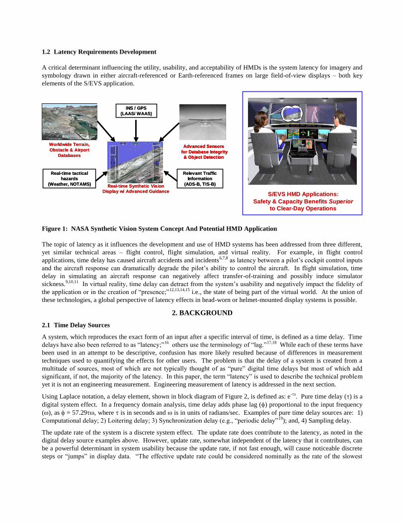
1.2 Latency Requirements Development
A critical determinant influencing the utility, usability, and acceptability of HMDs is the system latency for imagery and
symbology drawn in either aircraft-referenced or Earth-referenced frames on large field-of-view displays – both key
elements of the S/EVS application.
S/EVS HMD Applications: S/EVS HMD Applications:
Safety & Capacity BenefitsSafety & Capacity Benefits Superior Superior
to Clearto Clear--Day OperationsDay Operations
S/EVS HMD Applications: S/EVS HMD Applications:
Safety & Capacity BenefitsSafety & Capacity Benefits Superior Superior
to Clearto Clear--Day OperationsDay Operations
Worldwide Terrain,
Obstacle & Airport
Databases
Worldwide Terrain,
Obstacle & Airport
Databases
INS / GPS
(LAAS/ WAAS)
INS / GPS
(LAAS/ WAAS)
Real-time tactical
hazards
(Weather, NOTAMS)
Real-time tactical
hazards
(Weather, NOTAMS)
Relevant Traffic
Information
(ADS-B, TIS-B)
Relevant Traffic
Information
(ADS-B, TIS-B)Real-time Synthetic Vision
Display w/ Advanced Guidance
Real-time Synthetic Vision
Display w/ Advanced Guidance
Advanced Sensors
for Database Integrity
& Object Detection
Advanced Sensors
for Database Integrity
& Object Detection
Advanced Sensors
for Database Integrity
& Object Detection
Figure 1: NASA Synthetic Vision System Concept And Potential HMD Application
The topic of latency as it influences the development and use of HMD systems has been addressed from three different,
yet similar technical areas – flight control, flight simulation, and virtual reality. For example, in flight control
applications, time delay has caused aircraft accidents and incidents6,7,8
as latency between a pilot’s cockpit control inputs
and the aircraft response can dramatically degrade the pilot’s ability to control the aircraft. In flight simulation, time
delay in simulating an aircraft response can negatively affect transfer-of-training and possibly induce simulator
sickness.9,10,11
In virtual reality, time delay can detract from the system’s usability and negatively impact the fidelity of
the application or in the creation of “presence;”12,13,14,15
i.e., the state of being part of the virtual world. At the union of
these technologies, a global perspective of latency effects in head-worn or helmet-mounted display systems is possible.
2. BACKGROUND
2.1 Time Delay Sources
A system, which reproduces the exact form of an input after a specific interval of time, is defined as a time delay. Time
delays have also been referred to as “latency;”16
others use the terminology of “lag.”17,18
While each of these terms have
been used in an attempt to be descriptive, confusion has more likely resulted because of differences in measurement
techniques used to quantifying the effects for other users. The problem is that the delay of a system is created from a
multitude of sources, most of which are not typically thought of as “pure” digital time delays but most of which add
significant, if not, the majority of the latency. In this paper, the term “latency” is used to describe the technical problem
yet it is not an engineering measurement. Engineering measurement of latency is addressed in the next section.
Using Laplace notation, a delay element, shown in block diagram of Figure 2, is defined as: e-s
. Pure time delay () is a
digital system effect. In a frequency domain analysis, time delay adds phase lag () proportional to the input frequency
(), as = 57.29, where is in seconds and is in units of radians/sec. Examples of pure time delay sources are: 1)
Computational delay; 2) Loitering delay; 3) Synchronization delay (e.g., “periodic delay”19
); and, 4) Sampling delay.
The update rate of the system is a discrete system effect. The update rate does contribute to the latency, as noted in the
digital delay source examples above. However, update rate, somewhat independent of the latency that it contributes, can
be a powerful determinant in system usability because the update rate, if not fast enough, will cause noticeable discrete
steps or “jumps” in display data. “The effective update rate could be considered nominally as the rate of the slowest

component in the pathway of interest” 20
. A minimum of 15Hz is recommended for commercial Head-Up Displays21
but
other works show that this may be very optimistic.22
(Note that a 15 Hz update will cause a minimum of 100 msec
system latency due to one-half the update rate for a sampling delay of the input and 67 msec computational delay if only
one computation cycle is necessary to compute and display the system output from the input).
Input
e-sOutput
Laplacian Description of Time Delay
0 0.5 1 1.5 2 2.5 3 3.5 4 4.5 50
0.1
0.2
0.3
0.4
0.5
0.6
0.7
0.8
0.9
1
Input
e-s
Output
Time History of Time Delay
Time (sec)
Input
e-sOutput
Laplacian Description of Time Delay
0 0.5 1 1.5 2 2.5 3 3.5 4 4.5 50
0.1
0.2
0.3
0.4
0.5
0.6
0.7
0.8
0.9
1
Input
e-s
Output
Time History of Time Delay
Time (sec)
0 0.5 1 1.5 2 2.5 3 3.5 4 4.5 50
0.1
0.2
0.3
0.4
0.5
0.6
0.7
0.8
0.9
1
Input
e-s
Output
Time History of Time Delay
Time (sec)
Figure 2: Pure Time Delay Laplacian Description and Example Time History Response
A prominent source of latency, which is not a “pure time delay,” is caused by dynamic elements in the computational
path. A prime example would be the filtering of a head-tracker signal. While the filters attenuate noise in the head-
tracker signal, the undesirable side effect is the addition of phase lag, which manifests itself as latency.
In many studies, these different latency contributions, definitions, or measurements have not been well-understood.
Actual measurements have often not been made. From the technologies of flight simulation and flight control, two
latency measures have been developed and are accepted as standards because they are reliable, sensitive, measurable,
and valid as they are inclusive of all delay sources and types: “equivalent time delay” and “effective time delay.”6
2.2 Equivalent Time Delay
Equivalent time delay (see
) is measured by comparing the frequency response of the system against a desired system
output. Phase lag greater than the “desired” system is considered to be the “equivalent time delay” (Figure 3). For the
analysis of aircraft control laws, this analysis sometimes gets confounded23
by the definition of a “low order” desired
system response. However, in the analysis of HMD systems, the desired system response is trivial; the desired
amplitude ratio is unity (0 dB) and the phase lag is zero, as the HMD should respond without delay or amplification to
the system input. In this case, the “equivalent time delay” can be measured directly as the phase lag of the system
response to a sinusoidal input. While not called “equivalent delay,” researchers have generally recognized this latency
measurement issue and in many cases, are already measuring the system equivalent time delay.24,25,26,27
2.3 Effective Time Delay
Effective time delay (seffe
) provides, in most situations, the analogy (if not identical numerical value) to “equivalent
time delay,” but in the time-domain. Effective time delay is computed from a time history of the system output to a
sharp, abrupt system input, such as a step input. The effective delay is calculated from the time difference between the
system input and the maximum slope intercept of the system output. An example is shown in Figure 3 where the system
input is pilot’s lateral control input and the output is the aircraft roll rate response (p).
3. LATENCY RESEARCH IN S/EVS-RELATED APPLICATIONS
Latency research is reviewed from the technical disciplines of flight control, flight simulation and virtual reality research
to develop requirements for head-worn applications of S/EVS. Several obstacles with this approach are that: 1)
inconsistent latency definitions have been used in the different research projects; 2) latency measurements have not

always been made; and, 3) most comparisons/experiments were not to an “established” baseline; but rather, were relative
comparisons. Future research will, hopefully, address these deficiencies.
10-1
100
101
-50
-40
-30
-20
-10
0
10-1
100
101
-250
-200
-150
-100
-50
0
Frequency (rad/sec)
Frequency (rad/sec)
Phase
(deg)
Amplitude
(dB)
Frequency Range
Of Interest
Low Order
“Equivalent”
Model
“Equivalent” Time
Delay, e-tes
10-1
100
101
-50
-40
-30
-20
-10
0
10-1
100
101
-250
-200
-150
-100
-50
0
Frequency (rad/sec)
Frequency (rad/sec)
Phase
(deg)
Amplitude
(dB)
Frequency Range
Of Interest
Low Order
“Equivalent”
Model
“Equivalent” Time
Delay, e-tes
Equivalent DelayEquivalent Delay
RollRate,
p(deg/sec)
time (sec)
time (sec)
LateralPilot
ControlInput 50% input
63% p ss
pss
reff
eff
Effective DelayEffective Delay
RollRate,
p(deg/sec)
time (sec)
time (sec)
LateralPilot
ControlInput 50% input
63% p ss
pss
reff
eff
Effective DelayEffective Delay
10-1
100
101
-50
-40
-30
-20
-10
0
10-1
100
101
-250
-200
-150
-100
-50
0
Frequency (rad/sec)
Frequency (rad/sec)
Phase
(deg)
Amplitude
(dB)
Frequency Range
Of Interest
Low Order
“Equivalent”
Model
“Equivalent” Time
Delay, e-tes
10-1
100
101
-50
-40
-30
-20
-10
0
10-1
100
101
-250
-200
-150
-100
-50
0
Frequency (rad/sec)
Frequency (rad/sec)
Phase
(deg)
Amplitude
(dB)
Frequency Range
Of Interest
Low Order
“Equivalent”
Model
“Equivalent” Time
Delay, e-tes
Equivalent DelayEquivalent Delay
RollRate,
p(deg/sec)
time (sec)
time (sec)
LateralPilot
ControlInput 50% input
63% p ss
pss
reff
eff
Effective DelayEffective Delay
RollRate,
p(deg/sec)
time (sec)
time (sec)
LateralPilot
ControlInput 50% input
63% p ss
pss
reff
eff
Effective DelayEffective Delay
Figure 3: Equivalent and Effective Time Delay Computation Examples
From this review, conflicting evidence can be found on the effects of display delay. However, if interpreted from a
consistent pilot-vehicle interface standpoint, the data collectively unfolds into a plausible requirements basis.
3.1 Acceptable Latency Values: Pilot-Vehicle Dynamics System Analysis
The engineering analysis/analytical framework from which to evaluate these data, technologies and their resulting
influence on the pilot is provided by the pilot-vehicle dynamic system,28
is shown in Figure 4. This diagram identifies
the influencing factors and characteristics that “govern the ease and precision with which a pilot performs the tasks
required in support of an aircraft role.” The key element in this dynamic system is the pilot. The pilot acts as the
controller of this closed-loop system to complete a given task by making decisions, determining and taking corrective
actions, and evaluating and re-evaluating the results of these actions.
Pilot
AuralCues
Task
Stress
VisualCues
MotionCues
Control
Force Cockpit
FeelSystem
Control
Command Augmented
Aircraft
Aircraft
Response
External Disturbances -
Turbulence
Wind / X-Wind
Pilot
AuralCues
Task
Stress
VisualCues
MotionCues
Control
Force Cockpit
FeelSystem
Control
Command Augmented
Aircraft
Aircraft
Response
External Disturbances -
Turbulence
Wind / X-Wind
Figure 4: Pilot-Vehicle Dynamic System
The pilot in this system responds depending upon the sources and types of information or cues received, tailored by
individual training, experience, expertise, expectation, and real or apparent stress/workload. The information consists of

aural, visual, and motion cues, tactile feedback from cockpit interfaces/systems such as control stick movements, and
external disturbances, which are not necessarily correlated to the pilot’s control actions.
Review of the research shows that the effects of HMD delay, specific to S/EVS applications, depend predominantly
upon: 1) the required task; 2) the available visual cues; and, 3) the available motion cues, as described in the following.
3.2 Acceptable Latency Influences: Task Dependency
In the development of flight control systems, the United States Air Force military specification, based on years of
research, development, test and evaluation, stipulate a maximum of 100 msec equivalent time delay to ensure that the
aircraft flying qualities are satisfactory without improvement. Yet, with the addition of just another 140 msec (i.e., a
total equivalent delay of over 240 msec), aircraft controllability comes into question. The key factor in the background
of these requirements is that the task is a precisely defined, time-critical operation. The pilot must generate control
inputs, which achieve and maintain a high level of closed-loop pilot-vehicle performance.
When tasks require less precision or time-criticality, the pilot can relax their control inputs since a high level of system
performance is not required. Consequently, latency effects are significantly reduced. Equivalent delays over 350 msec
may be tolerated,6 unlike the data shown above. This same dependence of time delay effects on task requirements has
been found in other applications14
as it naturally follows that the required task drives the closed-loop system and the
criticality of the system latency.
3.3 Acceptable Latency Influences: Visual Cue Dependency
Acceptable latency values are shown to depend upon: the fidelity of the HMD visual cues and whether outside visual
cues are also available and used in the accomplishment of the task. The HMD visual cues are predominately the field-
of-view, resolution, and transmissivity of the HMD. Other factors will also be important such as color, brightness, etc.
but data guiding these effects are not as prevalent.
With an opaque HMD, subtending a moderate visual field-of-view (FOV), (48o H x 36
o V FOV and approximately 4.5
arc-min resolution), studies have shown that:
Users are very sensitive to display latency effects when they provide the only visual cues. Psychophysical
studies53
indicated that subjects can discriminate latency differences at least as low as 16.7 msec.
Virtual environment stability, or oscillopsia, which refers to the perception that the visual world appears to
swim about or oscillate,12
are a first-order effect of latency in opaque HMDs. As latency increased or head
rates increased, image stability was shown to degrade. Beyond oscillopsia, a primary concern has been the
possibility of visual-vestibular conflict, possibly leading to motion or simulator sickness33
(discussed later).
Lower latency promotes the sense of virtual environment “presence”: Participants in the lowest latency
condition (50 msec) had a higher self-reported sense of presence than a higher latency condition (90 msec)15
to
the extent that physiological measures of stress were statistically significant in the lower latency conditions.
Latency of visual information is not as noticeable and detrimental to the task if the (delayed) information extends only
into the pilots' foveal vision.
Ground simulation research (without motion) on latency effects in primary flight displays showed task
performance and pilot workload degradation, although shallow, was observable with increasing display delay.
These trends were supported by increased stick activity and degraded tracking performance.29
The United
States Navy established 150 msec as the maximum allowable display latency of all basic flight information.
Flight testing of a Head-Up Display (HUD) with delays up to 250 msec did not significantly affect task
performance and pilot workload if the aircraft otherwise exhibited good flying qualities (little motion delay) 22
.
A lack of prominent visual display latency effects stems from the small visual extent of the displays. Human perception
of motion30
is derived predominately from vestibular senses and peripheral vision cues.31
Vestibular motion cueing is
the most direct and accurate cue for “high frequency” motion effects, with peripheral visual cueing providing
supplement motion cueing (albeit delayed and degraded in comparison to vestibular sensing) and spatial orientation.
Foveal visual cues provide predominant attitude information but are relatively poor rate of motion sensors. A limited
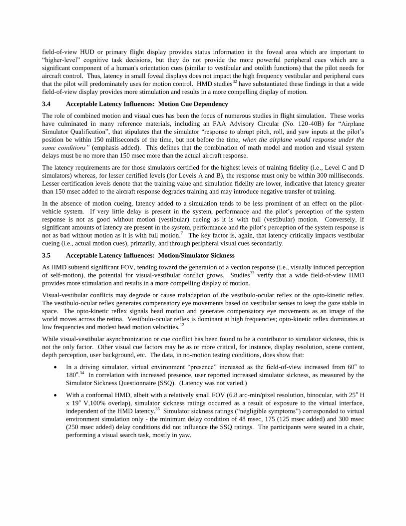
field-of-view HUD or primary flight display provides status information in the foveal area which are important to
“higher-level” cognitive task decisions, but they do not provide the more powerful peripheral cues which are a
significant component of a human's orientation cues (similar to vestibular and otolith functions) that the pilot needs for
aircraft control. Thus, latency in small foveal displays does not impact the high frequency vestibular and peripheral cues
that the pilot will predominately uses for motion control. HMD studies32
have substantiated these findings in that a wide
field-of-view display provides more stimulation and results in a more compelling display of motion.
3.4 Acceptable Latency Influences: Motion Cue Dependency
The role of combined motion and visual cues has been the focus of numerous studies in flight simulation. These works
have culminated in many reference materials, including an FAA Advisory Circular (No. 120-40B) for “Airplane
Simulator Qualification”, that stipulates that the simulator “response to abrupt pitch, roll, and yaw inputs at the pilot’s
position be within 150 milliseconds of the time, but not before the time, when the airplane would response under the
same conditions” (emphasis added). This defines that the combination of math model and motion and visual system
delays must be no more than 150 msec more than the actual aircraft response.
The latency requirements are for those simulators certified for the highest levels of training fidelity (i.e., Level C and D
simulators) whereas, for lesser certified levels (for Levels A and B), the response must only be within 300 milliseconds.
Lesser certification levels denote that the training value and simulation fidelity are lower, indicative that latency greater
than 150 msec added to the aircraft response degrades training and may introduce negative transfer of training.
In the absence of motion cueing, latency added to a simulation tends to be less prominent of an effect on the pilot-
vehicle system. If very little delay is present in the system, performance and the pilot’s perception of the system
response is not as good without motion (vestibular) cueing as it is with full (vestibular) motion. Conversely, if
significant amounts of latency are present in the system, performance and the pilot’s perception of the system response is
not as bad without motion as it is with full motion.7
The key factor is, again, that latency critically impacts vestibular
cueing (i.e., actual motion cues), primarily, and through peripheral visual cues secondarily.
3.5 Acceptable Latency Influences: Motion/Simulator Sickness
As HMD subtend significant FOV, tending toward the generation of a vection response (i.e., visually induced perception
of self-motion), the potential for visual-vestibular conflict grows. Studies33
verify that a wide field-of-view HMD
provides more stimulation and results in a more compelling display of motion.
Visual-vestibular conflicts may degrade or cause maladaption of the vestibulo-ocular reflex or the opto-kinetic reflex.
The vestibulo-ocular reflex generates compensatory eye movements based on vestibular senses to keep the gaze stable in
space. The opto-kinetic reflex signals head motion and generates compensatory eye movements as an image of the
world moves across the retina. Vestibulo-ocular reflex is dominant at high frequencies; opto-kinetic reflex dominates at
low frequencies and modest head motion velocities.12
While visual-vestibular asynchronization or cue conflict has been found to be a contributor to simulator sickness, this is
not the only factor. Other visual cue factors may be as or more critical, for instance, display resolution, scene content,
depth perception, user background, etc. The data, in no-motion testing conditions, does show that:
In a driving simulator, virtual environment “presence” increased as the field-of-view increased from 60o to
180o.34
In correlation with increased presence, user reported increased simulator sickness, as measured by the
Simulator Sickness Questionnaire (SSQ). (Latency was not varied.)
With a conformal HMD, albeit with a relatively small FOV (6.8 arc-min/pixel resolution, binocular, with 25o H
x 19o V,100% overlap), simulator sickness ratings occurred as a result of exposure to the virtual interface,
independent of the HMD latency.35
Simulator sickness ratings (“negligible symptoms”) corresponded to virtual
environment simulation only - the minimum delay condition of 48 msec, 175 (125 msec added) and 300 msec
(250 msec added) delay conditions did not influence the SSQ ratings. The participants were seated in a chair,
performing a visual search task, mostly in yaw.
With a 1280x1024 pixel resolution, binocular 60o H x 40
o V FOV
36 HMD consisting of a reported nominal
latency of 46 msec, simulator sickness ratings varied directly with time on task, not with HMD latency. The
results lend credence to the notion that time delay per se is not sufficient for the onset of simulator sickness.
In contrast to no-motion testing conditions, full motion testing conditions showed subtly different trends:
In an in-flight evaluation,37
an HMD degraded helicopter handling qualities because of reduced visual acuity,
limited FOV, and latency and caused pilot fatigue due to excessive helmet inertia. The HMD was provided a
substantial FOV (105o H x 45
o V FOV with 25
o Binocular Overlap); but it was coupled to an NTSC sensor
platform yielding only ~11 arc min line per pixel pair resolution. As a result, the HMD acuity was one of the
main factors affecting performance, reportedly providing only ~20/120 Snellen visual acuity. Some motion
sickness complaints (eye strain, uneasiness and helmet discomfort, stomach awareness) were reported and
significant changes in head-movement were noted when using the HMD. Pilots reported that they reduced head
rate movement and scanned the display with their eyes instead. The system latency was reported to be 90-120
msec but latency was not experimentally varied.
In a follow-on study,38
using the same HMD, 50 msec was reported as an effective time delay6 for the baseline
system latency and latency up to a total of 350 msec was added experimentally to the HMD system. In
addition, control system delays were experimentally varied. HMD acuity was still a main factor affecting
performance (i.e., visual acuity of ~20/120). However, the effects of visual (HMD) and control system latency
were reported to be very similar. The absence of handling qualities problems with this amount of flight control
system delay suggests that demanding piloting tasks could not flown because of the lack of HMD visual acuity.
Pilots were reported to adapt to the delay conditions. With increased HMD latency, the pilots tended to reduce
their head movements, especially in yaw. Pilots reported that large yaw head movements increased
disorientation and workload. Long visual delays, in tasks which required head-movements, prompted post-
flight discomfort. A follow-on simulator study showed a significant increase in reported simulator (motion)
sickness as the visual delay increased from the baseline condition to 350 msec total HMD latency.
In a related research area,39 subjects performed driving tasks in a military armored vehicle using four display
conditions: direct, periscope, head-slaved with normal camera lenses, and with wide-angle lenses. (Non-
conformal situation is ignored for this analysis). The driver’s HMD was coupled to a 2 DOF head-slave
stereoscopic camera system (heading and pitch). The opaque HMD provided 640x480 pixel resolution over a
48o H x 36
o V yielding approximately 4.5 arc-min resolution. In comparison of performance, driving with the
head-slaved conformal HMD was 50% better than the current equipage (periscope) but was still only 50% as
good as direct viewing. Three of seven subjects reported motion sickness symptoms after driving in an HMD
viewing condition and subsequently, withdrew from the experiment. Motion sickness was not expected with
the HMD – no reported problems in previous studies that involved direct view cameras and monitors. In this
experiment, it was hypothesized that four factors contributed to the motion sickness occurrences: 1) Omission
of image roll; 2) inherent delays between visual and vestibular (due to the HMD system latencies); 3) low
image quality; and/or, 4) offset between camera viewpoint and physical position of driver.
While not conclusive, these data indicate that visual-vestibular conflict will be a significant concern for head-worn
applications for S/EVS.
4. LATENCY REQUIREMENTS IN HEAD-WORN DISPLAY S/EVS APPLICATIONS
The following latency requirements are given based on the following assumptions of what the HMD requirements will
be for S/EVS applications:
The HMD will be used as a large field-of-regard display to create or augment the environment in which the
aircraft is being operated; it is not primarily a pointing or aiming device. The S/EVS information will be
conformally displayed.
The HMD will be see-through (>70% photopic transmissivity40
). The pilot will be able to see the cockpit
instrument displays (unless a “see-through” mode is selected by the pilot; whereby the pilot will be able to
display the S/EVS imagery at all aspects and thus, “look-through” the aircraft fuselage.)
In unrestricted day visibility conditions, the S/EVS imagery will be removed from the display (i.e., decluttered)
and only necessary flight symbology will be provided.
In marginal VMC, VMC on-top, night, or IMC conditions, the S/EVS imagery will be displayed and the HMD
provides the predominant but not only visual cues to the pilot. The degree that the S/EVS imagery will
predominant the pilot’s visual cues will depend upon the outside (i.e., background) illumination, coloration, and
visibility and the HMD field-of-view.
HMD display resolution will tend toward “eye limiting” resolutions (i.e., approaching 1 arc-min resolution).
4.1 Measurement
Both equivalent or effective time delay measures should be used in the analysis of HMD latencies to ensure reliability
and repeatability of analyses. Measurement, in general, is always needed because: a) these data are the only way to
verify performance against specification24
; b) these data are needed to evaluate where latency improvements can be
made26
; and, c) assumed latencies don’t necessarily meet reality due to unforeseen, because, without periodic
measurement, system latency can grow unexpectedly as a side effect from other system “upgrades.”41
Both equivalent or effective time delay measures should be used as numerical differences can be revealing in the
analysis and understanding of latency effects. In general, the two measures yield the same numeric result for linear
systems. Differences will arise for nonlinear systems or systems which are frequency-tailored, such as those that attempt
latency “compensation” or “prediction” as discussed later. As such, both measures should be used and also, the
equivalent time delay measurement should be computed using a fairly large frequency band.
The methods by which to measure equivalent or effective time delay should be repeatable, easily administered, and
preferable “in situ”; hence, special test software should be refrained from since often the special software may be
unrepresentative of the application. Some methods for measuring video system and HMD latencies have been
developed24,25,27,42,43
and may be applicable. Automatic testing methods are also very desirable.
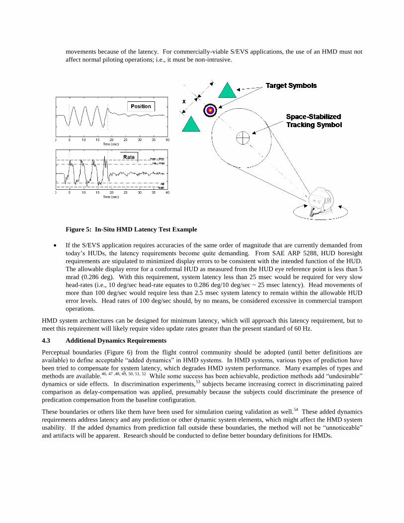
An easily administered in-situ latency measurement technique such as a “windshield washer” test, should be considered
as a psuedo built-in-test method (Figure 5) because of the importance that latency may have in system acceptability and
mission success. This test involves a space-stabilized, boresight symbol and an outer “target box” of known dimensions
located symmetrically on either side of the boresight symbol. In the presence of HMD latency, the boresight symbol
cannot remain perfectly space-stabilized. The test requires that the user smoothly oscillate their head in azimuth (or
elevation) at a rate which causes the space-stabilized symbol to touch the outer, target box. The head-movement rate
data divided by the size of the target box, defines the equivalent time delay (at one frequency). (Note that the latency in
the head movement data is immaterial to this computation; only the average rate is needed for the equivalent delay
calculation.) While automatic methods to make these measurements are desired for repeatability of results, a user can be
easily trained to obtain this data. Ranges of target box sizes should be used to test for linearity and multiple frequencies
as necessary for frequency-tailoring effects analysis.
4.2 Overall Requirement
The end-to-end latency for an HMD supporting an S/EVS application should be no greater than 20 msec equivalent or
effective time delay. This requirement is based on the following principles:
In the definition of HMD latency requirements for S/EVS, a worse-case task requirement should be assumed.
Therefore, the latency requirements will be stringent because, as shown previously, the latency influences are
pronounced for demanding piloting tasks. If lesser task demands are envisioned, the latency requirements may
be relaxed, but this should not be assumed a priori.
HMD experiments have shown that subjects moved their heads less, but faster with large FOVs than with small
FOVs.44
Large FOVs are assumed to be required for S/EVS applications. Thus, latency will tend to trigger
oscillopsia. Visual-vestibular conflicts will be a prominent concern for S/EVS applications of HMDs.
Others have conjectured HMD latency requirements to be:45
50 msec preferred, 100 msec marginal, 150 msec
unacceptable. However, the visual acuity of the HMD in this test did not approach “eye limiting resolutions”;
hence, lower pilot-task demands were evident and the evaluation pilots noted a tendency to modify their head
movements because of the latency. For commercially-viable S/EVS applications, the use of an HMD must not
affect normal piloting operations; i.e., it must be non-intrusive.
Figure 5: In-Situ HMD Latency Test Example
If the S/EVS application requires accuracies of the same order of magnitude that are currently demanded from
today’s HUDs, the latency requirements become quite demanding. From SAE ARP 5288, HUD boresight
requirements are stipulated to minimized display errors to be consistent with the intended function of the HUD.
The allowable display error for a conformal HUD as measured from the HUD eye reference point is less than 5
mrad (0.286 deg). With this requirement, system latency less than 25 msec would be required for very slow
head-rates (i.e., 10 deg/sec head-rate equates to 0.286 deg/10 deg/sec ~ 25 msec latency). Head movements of
more than 100 deg/sec would require less than 2.5 msec system latency to remain within the allowable HUD
error levels. Head rates of 100 deg/sec should, by no means, be considered excessive in commercial transport
operations.
HMD system architectures can be designed for minimum latency, which will approach this latency requirement, but to
meet this requirement will likely require video update rates greater than the present standard of 60 Hz.
4.3 Additional Dynamics Requirements
Perceptual boundaries (Figure 6) from the flight control community should be adopted (until better definitions are
available) to define acceptable “added dynamics” in HMD systems. In HMD systems, various types of prediction have
been tried to compensate for system latency, which degrades HMD system performance. Many examples of types and
methods are available.46, 47 ,48, 49, 50, 51, 52
While some success has been achievable, prediction methods add “undesirable”
dynamics or side effects. In discrimination experiments,53
subjects became increasing correct in discriminating paired
comparison as delay-compensation was applied, presumably because the subjects could discriminate the presence of
predication compensation from the baseline configuration.
These boundaries or others like them have been used for simulation cueing validation as well.54
These added dynamics
requirements address latency and any prediction or other dynamic system elements, which might affect the HMD system
usability. If the added dynamics from prediction fall outside these boundaries, the method will not be “unnoticeable”
and artifacts will be apparent. Research should be conducted to define better boundary definitions for HMDs.

5. CONCLUDING REMARKS
Head-worn or helmet-mounted display systems are being proposed as one method in which to create spatially-integrated,
large field-of-regard information display systems, specifically using S/EVS. System delays or latencies inherent to these
displays have been shown to critically influence the display utility, usability, and acceptability. Research results from
three different, yet similar technical areas – flight control, flight simulation, and virtual reality – have been collated to
create a proposed requirements. Consistent definitions and measurement techniques are proposed herein for universal
application and latency requirements for Head-Worn Display S/EVS applications. Based upon the most stringent
requirements for HMD applications of S/EVS (i.e., demanding tasks using a high resolution, large field-of-view head-
worn display), the system latency must be less than 20 msec. Future research areas are defined.
Figure 6: Maximum “Unnoticeable” Differences in Gain and Phase Response.
REFERENCES
1.) Baize, D.G. and Allen, C.L., Synthetic Vision Systems Project Plan, Version IIId, NASA Langley Research Center,
5 Nov 2001.
2.) Bailey, R. E., Parrish, R. V., Arthur, J. J., III, and Norman, R. M.: Flight Test Evaluation of Tactical Synthetic
Vision Display Concepts in a Terrain-Challenged Operating Environment . Proceedings of SPIE: Enhanced and
Synthetic Vision 2002, Vol. 4713, 2002, pp. 178-189.
3.) Kramer, L.J., Prinzel, L.J., Bailey, R.E., & Arthur, J.J.: Synthetic Vision Enhances Situation Awareness And RNP
Capabilities For Terrain-Challenged Approaches. Proceedings of the American Institute of Aeronautics and
Astronautics Third Aviation Technology, Integration, and Operations Technical Forum, AIAA 2003-6814, pp. 1-11.
4.) Arthur, J.J., Prinzel, L.J., Kramer, L.J., Bailey, R.E., and Parrish, R.V.: CFIT Prevention Using Synthetic Vision.
SPIE. In Proceedings of SPIE, Enhanced and Synthetic Vision 2003, Editor: Jacuqes G. Verly, Vol. 5018
5.) Newman, R.L. and Greeley, K.W.: HMD Symbol Stabilization Concepts. In SPIE Conference on Helmet- and
Head-Mounted Displays and Symbology Design Requirements II, Vol. 2465, April 1995, pp. 165-174.
6.) Smith, R.E. and Bailey, R.E.: Effect of Control System Delays on Fighter Flying Qualities. in Criteria for
Handling Qualities of Military Aircraft, In AGARD Flight Mechanics Conference Proceedings No. 333, Apr. 1982.
7.) Bailey, R.E.; and Knotts, L.H: Effects of Time Delay on Manual Flight Control and Flying Qualities During In-
Flight and Ground-Based Simulation. AIAA Flight Simulation Conference, AIAA-87-2370, Aug. 1987.

8.) Bailey, R.E.: The Flying Qualities Influence of Delay in the Fighter Pilot's Cuing Environment. in Flying Qualities.
AGARD Flight Mechanics Panel Conference Proceedings Number 508, October 1990.
9.) Riccio, G.E., Cress, J.D., and Johnson, W.V.: The Effects of Simulator Delays on the Acquisition of Flight Control
Skills: Control of Heading and Altitude. Proceedings of the Human Factors Society Annual Meeting, New York,
NY: Human Factors Society, 1987.
10.) Gum, D.R. and Martin, E.A., The Flight Simulator Time Delay Problem. AIAA Paper 87-2369-CP, Monterey, CA,
August 1987.
11.) Motion Cues in Flight Simulation and Simulator Induced Sickness, AGARD Conference Proceedings No. CP-433.
Neuilly Sur Seine, France. 1988.
12.) Allison, R. S., Harris, L.R., Jenkin, M., Urszula, J., and Zacher, J.E., Tolerance of Temporal Delay in Virtual
Environments. Virtual Reality, 2001. Proceedings IEEE, 13-17 March 2001, pp. 247-254.
13.) So, R.H.Y., and Griffin, M.J.: Effects of Time Delays on Head-Tracking Performance and the Benefits of Lag
Compensation by Image Deflection. AIAA-91-2926-CP, pp. 124-130.
14.) Ellis, S.R., Bréant, F., Menges, B., Jacoby, R., and Adelstein, B.D.: Factors Influencing Operator Interaction with
Virtual Objects Viewed via Head-Mounted See-Through Displays: Viewing Conditions and Rending Latency. IEEE
Virtual Reality Annual International Symposium, 1-5 March 1997, pp. 138-145.
15.) Meehan, M., Razzaque, S., Whitton, M.C., and Brooks, F.P., Jr.: Effect of Latency on Presence in Stressful Virtual
Environments. Proceedings of IEEE Virtual Reality 2003, Los Angeles , CA, March 2003, pp. 141-148.
16.) Kranz, Y.: Latency: Requirements and Implementation of a Helmet-Mounted Cueing System (HMCS) in a Fast Jet.
SPIE Conference on Helmet- and Head-Mounted Displays IV, Vol. 3689, Orlando, FL, April 1999, p. 135-142.
17.) Wloka, M.W.: Lag in Multiprocessor Virtual Reality. In Presence: Teleoperators and Virtual Environments, Vol.
4, No. 1, pp 50-63.
18.) Bryson, S., and Fisher, S.S.: Defining, Modeling, and Measuring System Lag in Virtual Environments. SPIE Vol.
1256, Stereoscopic Displays and Applications, 1990, pp. 98-109.
19.) McFarland, R.E.: CGI Delay Compensation. NASA TM 86703, January 1986.
20.) Jacoby, R., Adelstein, B., and Ellis, S. (1996): Improved Temporal Response in Virtual Environment Hardware and
Software. in Conference on Stereoscopic Displays and Applications VII, SPIE. Vol. 2653, pp. 271-284.
21.) SAE ARP 5288: Aerospace Recommended Practices for Transport Category Airplane HUD Systems
22.) Bailey, R.E., Effect of Head-Up Display Dynamics on Fighter Flying Qualities. Journal of Guidance Control and
Dynamics, Vol. 12, No. 4, July-Aug 1989, pp. 514-520.
23.) Hodgkinson, J.: Equivalent System Criteria for Handling Qualities of Military Aircraft. In AGARD Flight
Mechanics Panel Conference Proceedings No. 333, Criteria for Handling Qualities of Military Aircraft, April 1982.
24.) Miller, Dorian and Gary Bishop: Latency Meter: a Device for Easily Monitoring VE Delay. in Proceedings of SPIE
Vol. #4660 Stereoscopic Displays and Virtual Reality Systems IX, San Jose, CA, January 2002.
25.) Mine, M.R.. Characterization of End-to-End Delays in Head-Mounted Display Systems. University of North
Carolina Technical Report TR93-001, Department of Computer Science, Chapel Hill, NC, 1993.
26.) Jacobs, M.C., Livingston, M.A., and State, A.: Managing Latency in Complex Augmented Reality Systems.
SIGGRAPH: ACM Special Interest Group on Computer Graphics and Interactive Techniques, Proceedings of the
1997 symposium on Interactive 3D graphics, Rhode Island, USA,
27.) Adelstein, B.D., Johnson, E.R, and Ellis, S.R. (1996): Dynamic Response of Electromagnetic Spatial Displacement
Trackers. In Presence: Teleoperators and Virtual Environments, Vol. 5, No. 3, pp. 302-318.
28.) Harper, R.P. Jr. and Cooper, G.E.: Wright Brothers Lectureship in Aeronautics: Handling Qualities and Pilot
Evaluation, AIAA/AHS/ASEE Aircraft Design Systems and Operations Meeting, Paper No. AIAA-84-2442.
Oct.31-Nov 2, 1984, San Diego, CA
29.) Johns, J.B. and Funk, J.D.: Impact of V-22 Display Latency on Flying Qualities. Naval Air Development Center
Report NADC-91040-60, August 1991.
30.) Meiry, J.L.: The Vestibular System and Human Dyanmic Space Orientation, Massachusetts Institute of
Technology, Man-Vehicle Control Laboratory Report T-65-1, Cambridge, MA, June 1965.
31.) Hosman, R.J.A.W.: Visual-Vestibular Interaction in the Perception and Control of Aircraft Motions by the Pilot.
AIAA Paper No. A97-37232, August 1997.

32.) Pausch. R., Crea, T., and Conway, M. (1992): A Literature Survey for Virtual Environments and Simulator
Sickness. In Presence, Vol. 1, Number 3, pp. 344-363.
33.) Pausch. R., Crea, T., and Conway, M. (1992): A Literature Survey for Virtual Environments and Simulator
Sickness. In Presence, Vol. 1, Number 3, pp. 344-363.
34.) Lin, J. J-W et al: Effects of Field-of-View on Presence, Enjoyment, Memory and Simulator Sickness in a Virtual
Environment. Proceedings of the IEEE Virtual Reality 2002 Conference
35.) Draper, M.H., Viire, E.S., Furness, T.A., and Gawron, V.J. Effects Of Image Scale And System Time Delay On
Simulator Sickness Within Head-Coupled Virtual Environments. Human Factors, 43(1), Spring 2001, pp. 129 - 146
36.) Nelson, W.T., et al: Assessing Simulator Sickness In A See-Through HMD: Effects of Time Delay, Time on Task,
and Task Complexity. IMAGE 2000 Conference, Scottsdale, AR, 10-14 July 2000.
37.) Jennings, S., Gubbels, A. W., Swail, C.P., and Craig, G.: In-Flight Evaluation of a Fibre Optic Helmet-Mounted
Display. Proceedings of SPIE: Helmet- and Head-Mounted Displays III, Vol. 3362, 1998, pp. 126-135
38.) Jennings, S.: The Effects of Time Delays in Visually-Coupled Systems On Helicopter Control During Flight Test
and Simulation. Under Review, Journal of Aircraft
39.) Oving, A.B., and van Erp, J.B.F.: Driving with a Head-Slaved Camera System. Proceedings of the Human Factors
and Ergonomics Society 45th Annual Meeting - 2001, pp. 1372-1376
40.) Rash, C.E., Helmet-Mounted Displays: Design Issues for Rotary-Wing Aircraft. United States Army Aeromedical
Research Laboratory and United States Army Medical Research and Materiel Command, Fort Rucker, AL
41.) Horowitz, S.J.: Measurements and Effects of Transport Delays in a State-of-the-art F-16C Flight Simulator, AIAA
Flight Simulation Technologies Conference, AIAA-87-2368, August 1987
42.) Smith, R.M.: A Method for Determining Transport Delays in The Flight Simulation Environment, AIAA Paper No.
AIAA-91-2964-CP., August 1991.
43.) Slutz, G.J and Ewart, R.B: An Electronic Visual Display Attitude Sensor (EVDAS) For Analysis of Flight Simulator
Delays. AIAA Paper No. AIAA-92-4167-CP., August 1992.
44.) Wells, M.J., and Venturino, M.: Performance and Head-Movements Using A Helmet-Mounted Display with
Different Sized Fields of View. Optical Engineering, August 1990, Vol. 29, No. 8, pp. 870-877.
45.) Link, N.K., Kruk, R.V., McKay, D., Jennings, S., and Craig, G.: Hybrid Enhanced and Synthetic Vision System
Architecture for Rotorcraft Operations. Proceedings of SPIE: Enhanced and Synthetic Vision 2002, Vol. 4713,
2002, pp. 190-201.
46.) Adelstein, B.D., Jung, J.Y, and Ellis, S.R.: Predictive Compensator Optimization for Head Tracking Lag in Virtual
Environments. NASA TM-2001-209627, Mar. 2001
47.) Akatsuka, Y., and Bekey, G.A.: Compensation for End to End Delays in a VR System. Virtual Reality Annual
International Symposium, Proceedings IEEE, 14-18 March 1998, pp. 156-159.
48.) Emura, S. and Tachi, S.: Compensation Of Time Lag Between Actual And Virtual Spaces By Multi-Sensor
Integration. IEEE International Conference on Multi-sensor Fusion and Integration for Intelligent Systems, 2-5 Oct.
1994, pp: 463 -469
49.) Kiruluta, A., Eizenman, M., and Pasupathy, S. (1997): Predictive Head Movement Tracking Using a Kalman Filter.
IEEE Transactions on Systems, Man, and Cybernetics, Vol. 27, No. 2, pp. 326-331.
50.) Saad, E.W., Caudell, T.P., and Wunsch, D.C. II: Predictive Head Tracking for Virtual Reality. IJCNN '99.
International Joint Conference on Neural Networks, Volume: 6, 10-16 July 1999, pp. 3933 –3936.
51.) So, R.H.Y., and Griffin, M.J.: Experimental Studies of the Use of Phase Lead Filters To Compensate Lags in Head-
Coupled Visual Displays. IEEE Transactions, Systems, Man, and Cybernetics, Vol. 26, No. 4, pp. 445-454.
52.) Nelson, W.T., et al: Compensation For the Effects of Time Delay in a Helmet-Mounted Display: Perceptual
Adaptation Versus Algorithmic Prediction. in SPIE Proceedings of Helmet- and Head-Mounted Displays and
Symbology Design Requirements II, Orlando, FL, 18-19 April 1995.
53.) Jung, J.Y., Adelstein, B.D., and Ellis, S.R.: Discriminability of Prediction Artifacts in a Time-Delayed Virtual
Environment. Proceedings of the IEA 2000/HFES 2000 Congress, pp. 499-502.
54.) Galloway, R.T. and Smith, R.B.: Simulation Cue Validation Using Frequency Response Techniques. AIAA Paper
No. 96-3528, AIAA Flight Simulation Technologies Conference, San Diego, CA. August 1996.