lcds and the arduino - springer · lcds and the arduino ... command-control codes (courtesy of...
TRANSCRIPT
179
CHAPTER 8
LCDs and the Arduino
Making machines talk to humans is quite easy using light indicators or other illumination devices. The most common way of providing information is through a visible light source. By establishing a protocol (set of rules), a messaging scheme is created based on the application definition.
Incandescent lightbulbs were once the component of choice for visual indicators because of their ability to alert someone of a change in a process or the approaching of a dangerous threshold. LEDs improved on the incandescent lightbulb because of low thermals (heat), small size, and greater longevity.
With the arrangement of seven discrete LEDs into a single package, sophisticated messages can be created because of the optoelectronic device’s ability to be wired for displaying numbers and letters. The ability to make alphanumerics (numbers and letters) with multiplexed seven-segment LED displays allows long messages to be displayed easily. Although seven-segment LED displays are better than both discrete LEDs and incandescent lightbulbs for visual information, washout and heat are problems with the optoelectronic part of the seven-segment LED. (Washout is the effect of the sun making LEDs hard to see in daylight).
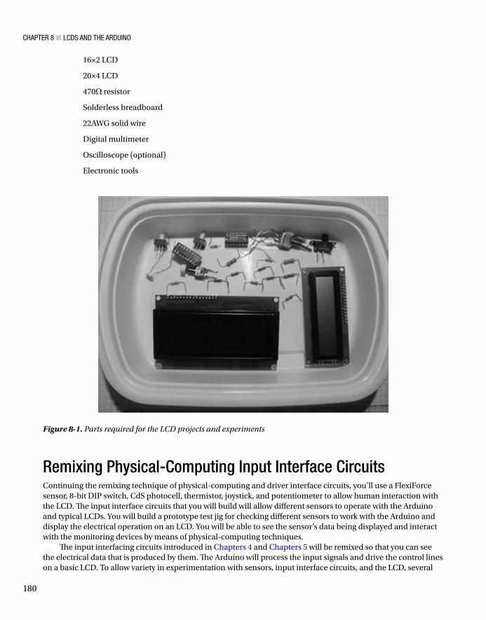
The LCD (liquid crystal display) eliminates both heat and washout, and can be packaged to create characters and sophisticated graphics as well. In this chapter, we’ll investigate the LCD using an experimental test jig that allows individual numbers, characters, and letters to be displayed based on an 8-bit binary code. Also, we’ll explore physical-computing techniques for using the Arduino to create text messages by interacting with an LCD using a variety of solid-state and electromechanical sensors. Figure 8-1 shows the parts required for the hands-on projects and experiments.
Parts ListArduino Duemilanove or equivalent
11 47K resistors
470K resistor
4 10K resistors
CdS photocell
8-bit DIP switch
74LS00 or 7400 NAND Logic IC
SPDT (single-pole, double-throw) switch
SPST (single-pole, single-throw) switch
Learn Electronics with Arduino© Donald ilcher 2012
D. Wilcher,
W
CHAPTER 8 LCDS AND THE ARDUINO
180
16×2 LCD
20×4 LCD
470 resistor
Solderless breadboard
22AWG solid wire
Digital multimeter
Oscilloscope (optional)
Electronic tools
Figure 8-1. Parts required for the LCD projects and experiments
Remixing Physical-Computing Input Interface CircuitsContinuing the remixing technique of physical-computing and driver interface circuits, you’ll use a FlexiForce sensor, 8-bit DIP switch, CdS photocell, thermistor, joystick, and potentiometer to allow human interaction with the LCD. The input interface circuits that you will build will allow different sensors to operate with the Arduino and typical LCDs. You will build a prototype test jig for checking different sensors to work with the Arduino and display the electrical operation on an LCD. You will be able to see the sensor’s data being displayed and interact with the monitoring devices by means of physical-computing techniques.
The input interfacing circuits introduced in Chapters 4 and Chapters 5 will be remixed so that you can see the electrical data that is produced by them. The Arduino will process the input signals and drive the control lines on a basic LCD. To allow variety in experimentation with sensors, input interface circuits, and the LCD, several
CHAPTER 8 LCDS AND THE ARDUINO
181
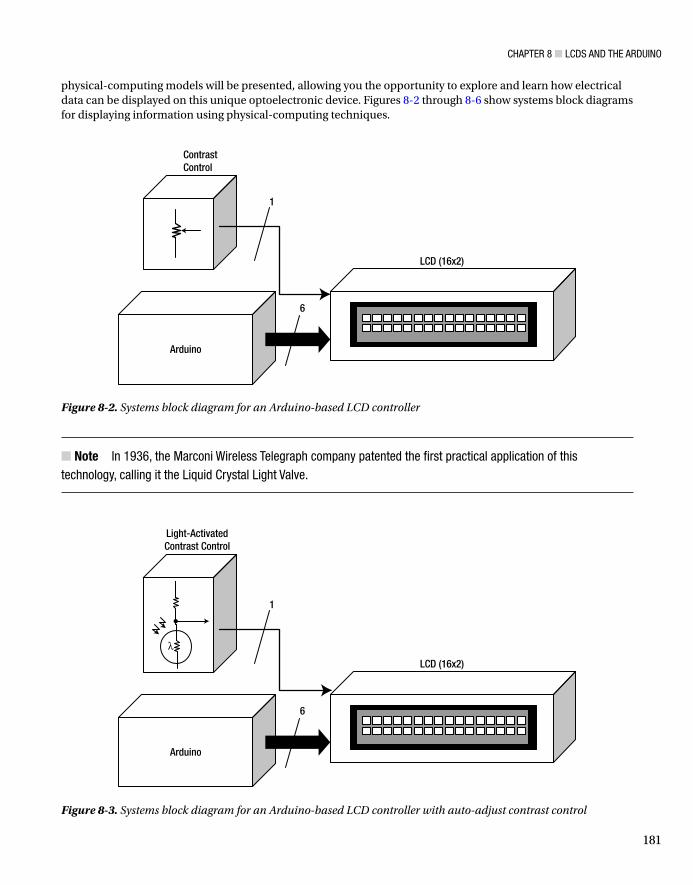
physical-computing models will be presented, allowing you the opportunity to explore and learn how electrical data can be displayed on this unique optoelectronic device. Figures 8-2 through 8-6 show systems block diagrams for displaying information using physical-computing techniques.
ContrastControl
Arduino
LCD (16x2)
1
6
Figure 8-2. Systems block diagram for an Arduino-based LCD controller
Note In 1936, the Marconi Wireless Telegraph company patented the first practical application of this technology, calling it the Liquid Crystal Light Valve.
Arduino
Light-ActivatedContrast Control
LCD (16x2)
1
6
Figure 8-3. Systems block diagram for an Arduino-based LCD controller with auto-adjust contrast control

CHAPTER 8 LCDS AND THE ARDUINO
182
1
61
Arduino
ContrastControl
LCD (16x2)
Light Detection Sensor
Figure 8-6. Systems block diagram for an Arduino-based LCD controller with light detection
1
61
Arduino
SPDT Switchwith DebounceControl
ContrastControl
LCD (16x2)
Figure 8-5. Systems block diagram for an Arduino-based LCD controller with an improved event trigger
1
61
Arduino
PB Switch
ContrastControl
LCD (16x2)
Figure 8-4. Systems block diagram for an Arduino-based LCD controller with simple event detection
Note By keeping the core Arduino-based LCD controller design and changing the input interface detection circuit, five new devices were created quite easily. Can you say “imagination”?

CHAPTER 8 LCDS AND THE ARDUINO
183
The five Arduino LCD controllers I’ve shown are examples of creating new physical-computing designs using different input detection circuits. In the pages to follow, I will show how to develop each one of these input circuit–operated LCD controllers with a few junk-box electronic parts. To build these devices, I will introduce an evaluation-kit approach to wiring the interface circuits to the Arduino-operated LCD controller.
How It Works: The LCD Test JigThe approach I’m going to take in explaining the basics of an LCD is to use the test jig systems block diagram shown in Figure 8-7. As shown in the diagram, there are four main subcircuits required to display characters, letters, and numbers on an LCD. The 8-bit binary code circuit provides the necessary data for changing the LCD operation or displaying characters and/or alphanumerics.
ContrastControl
00001111
8-Bit Binary Code
8
1
1
1
ENABLE Switchwith DebounceControl
REGISTER SELECT Switch
D
Clk
Q0
Q0’
D
Clk
Q1
Q1’
LCD(16x2)
Figure 8-7. Systems block diagram for the LCD test jig

CHAPTER 8 LCDS AND THE ARDUINO
184
The operation of the LCD is based on simple command-control codes. Figure 8-8 shows a table listing the command-control codes for the LCD. As shown in the table, LCD display operations such as Clear Display, Display & Cursor Home, and Display On/Off & Cursor are executed by entering an 8-bit binary code.
Figure 8-8. Command-control codes (courtesy of Everyday Practical Electronics)
The data entry of the 8-bit code is done by using an 8-bit DIP switch. By setting the individual switches to either Open or Closed, discrete binary bits of 1 or 0 will be fed to the eight data lines (D7–D0) of the LCD.
The contrast control is a potentiometer responsible for adjusting the visibility of the discrete LCD squares.The Enable switch allows the 8-bit code entered using the DIP switch to be sent to the LCD’s data lines. This
switch is debounced to prevent sporadic data entry of the 8-bit code from being displayed on the LCD. Figure 8-9 shows the Debounce switch’s circuit schematic diagram, and the operation of the debounce circuit is illustrated in Figure 8-10.
If you don’t wire this circuit to pin 6 of the LCD and use an ordinary switch, the LCD will show multiple letters after each switch toggle, which is not a cool thing. Figure 8-11 shows the complete circuit schematic diagram for the LCD test jig. The LCD test jig prototype is shown in Figure 8-12.
The Register Select switch is used to put the LCD in either command-control or alphanumeric/character mode. I used this switch to set up the LCD test jig by placing it in command-control mode. After wiring the LCD, I placed the switch in the alphanumeric/character mode position to allow the LCD display to show letters, numbers, and special characters using the correct 8-bit code. Figure 8-13 shows the table of letters, numbers, and characters. Notice the table is divided into upper and lower bits. It’s very important that you enter the binary data on the 8-bit DIP switch in proper order. If you don’t, strange characters or a blank screen will be displayed on the LCD. The upper four bits relate to DIP switches D7 through D4 and the lower bits use the remaining D3 through D0 data lines.

CHAPTER 8 LCDS AND THE ARDUINO
185
R147K
+5VDC
R247K
Set Reset Switch
1
2
4
5
U1-B74LS00or 7400
U1-A74LS00or 7400
3
14
Clean Pulse
QSet Reset
6
7
Q-NOT
Figure 8-9. A debounce circuit using two NAND logic gates
Tip If an 8-bit DIP switch is not available, individual slide switches can be used instead. More than one way to skin a cat!
To use the command-control codes to do a specific operation for the LCD, you should have the Register Select switch in a binary 0 position. Place a digital or analog voltmeter across the switch and adjust it so 0 volts is displayed on the meter. Adjust the contrast control (10K potentiometer) so the squares on the LCD are slightly visible.
Next, set the 8-bit DIP switch using the binary code 00001111 and toggle the Enable switch. A small square will flash at the left side of the LCD.
Entering a letter, number, or character is quite easy as well. Toggle the Register Select switch and enter 01000001 on the 8-bit DIP switch. Toggle the Enable switch, and the letter A will be displayed on the LCD.
The flashing square moves to the right side on the LCD screen with each binary code entered using the 8-bit DIP switch. For the final exam, enter 00111000 on the 8-bit DIP switch, and the number 8 will be displayed on the LCD. You can make some unique and cool messages by entering the 8-bit binary code on the DIP switch. Try displaying your name on the LCD using a series of 8-bit binary codes. The test jig can be used to check other LCDs you may have sitting in a junk box in your lab or workshop. What a cool way to test your surplus LCDs using this awesome testing device!

186
Figure 8-11. The LCD test jig
Reset
R147K
+5VDC
R247K
Set Reset Switch
Noisy PulseSwitch Con
Set
R147K
+5VDC
Set Reset Switch
1
2
U1-A74LS00or 7400
3
14
Figure 8-10. Contact bounce and debounce circuit operation

CHAPTER 8 LCDS AND THE ARDUINO
187
Tip Remember, with an active-low switch, a binary 1 means “Open contacts” and a binary 0 means “Closed contacts.” And always use a Debounce switch when building digital circuits that need a smooth sequential operation. That’s how you do the Binary Slide!
The Real “Hello World”: Arduino and the LCDThe test jig provides a cool way to understand the operation of the LCD, but making messages is quite a slow and long task. The Arduino makes it a snap because all you need is six control lines and a basic sketch. You wire the Arduino to the LCD using the circuit schematic shown in Figure 8-14.
In the circuit schematic diagram, I’m using a standard LCD with 20×4 white text on a blue background. Some key features about the LCD are listed here:
The LCD is 20 characters wide and 4 rows tall.
It has white text on a blue background.
Its connection port has a 0.1-inch pitch and is single-row, allowing for easy breadboarding and wiring.
It includes a single LED backlight that can be dimmed easily with a resistor or PWM, and it uses much less power than an LCD with EL (electroluminescent) backlights.
It can be fully controlled with only six digital lines.
It has a built-in character set that supports English and Japanese text (see the HD44780 datasheet for the full character set).
Up to eight extra characters can be created for custom glyphs (such as special accent marks) for foreign-language support.
Figure 8-12. The LCD test jig prototype: Complete build (left) and LCD close-up (right)

CHAPTER 8 LCDS AND THE ARDUINO
188
Figure 8-15 shows the actual kit I purchased from Adafruit Industries to build the different LCD projects in this chapter.
The basic circuits of this LCD module, as well as other optoelectronic versions, consist of a controller IC, LCD panel, driving IC, and backlight driver. The controller IC is responsible for operating the six control lines, consisting of the Register Select (RS), Enable (E), Contrast Control (V0), Read/Write (R/W), Source Supply Voltage (Vss), and Drain Supply Voltage (Vdd). The controller IC sends the 8-bit binary data available on its data
Lower Four Bits
Upper Four Bits
Figure 8-13. The LCD letters, numbers, and character codes (courtesy of Everyday Practical Electronics)

CHAPTER 8 LCDS AND THE ARDUINO
189
lines (DB7–DB0) to the LCD panel for displaying letters, characters, and numbers. The driving IC operates the LCD panel by applying the correct voltage and current levels to it. Last, and optional on some LCD modules, there is a backlight LED used to light up the device for nighttime viewing. The systems block diagram for an LCD module is shown in Figure 8-16.
Figure 8-14. Circuit schematic for the Arduino-based LCD controller. LCD power pins: Vss equals 1 and Vdd equals 2
Figure 8-15. Standard 20×4 LCD with header pins and 10K potentiometer (courtesy of Adafruit Industries)

CHAPTER 8 LCDS AND THE ARDUINO
190
The circuit schematic diagram shown in Figure 8-14 will allow you to display the familiar “Hello World” message on the 20×4 LCD module. You can adjust the contrast of the LCD using the 10K potentiometer. The Arduino LCD controller I built from the circuit schematic diagram is shown in Figure 8-17. The wiring technique used in connecting the LCD correctly to the Arduino is to align the 16 pins to their corresponding numbers on the solderless breadboard. Using this layout technique, I had no wiring errors when connecting the LCD to the Arduino and the contrast control (10K potentiometer). After you have completed the wiring of the LCD circuit, turn on the power supply, and the LCD module will display segmented squares for a few seconds, and then light up with a bluish glow. You can adjust the sharpness of the display to your liking using the contrast control.
The next step is to upload the Hello World sketch to the Arduino. The Hello World sketch is shown in Listing 8-1.
VSSVDD
V0
RS
R/W
E
DB0~DB7
CONTROL IC
DRIVING IC
LCD PANEL
BACK LIGHTLED+
LED–
Figure 8-16. Systems block diagram for an LCD module (courtesy of Tinsharp datasheet)
Figure 8-17. An Arduino-based LCD controller prototype
CHAPTER 8 LCDS AND THE ARDUINO
191
Note In addition to selling Arduinos and accessory kits (shields), Adafruit Industries also stocks electronic parts, toolkits, and electronic tech books. Can you say “one-stop store”?
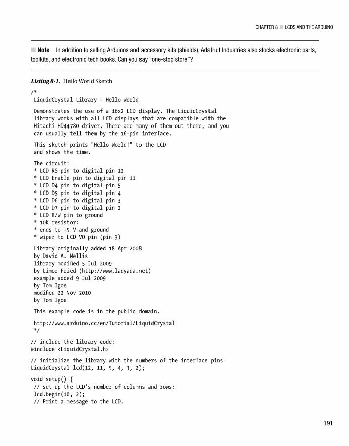
Listing 8-1. Hello World Sketch
/* LiquidCrystal Library - Hello World
Demonstrates the use of a 16x2 LCD display. The LiquidCrystal library works with all LCD displays that are compatible with the Hitachi HD44780 driver. There are many of them out there, and you can usually tell them by the 16-pin interface.
This sketch prints "Hello World!" to the LCD and shows the time.
The circuit: * LCD RS pin to digital pin 12 * LCD Enable pin to digital pin 11 * LCD D4 pin to digital pin 5 * LCD D5 pin to digital pin 4 * LCD D6 pin to digital pin 3 * LCD D7 pin to digital pin 2 * LCD R/W pin to ground * 10K resistor: * ends to +5 V and ground * wiper to LCD VO pin (pin 3)
Library originally added 18 Apr 2008 by David A. Mellis library modified 5 Jul 2009 by Limor Fried (http://www.ladyada.net) example added 9 Jul 2009 by Tom Igoe modified 22 Nov 2010 by Tom Igoe
This example code is in the public domain.
http://www.arduino.cc/en/Tutorial/LiquidCrystal */
// include the library code:#include <LiquidCrystal.h>
// initialize the library with the numbers of the interface pinsLiquidCrystal lcd(12, 11, 5, 4, 3, 2);
void setup() { // set up the LCD's number of columns and rows: lcd.begin(16, 2); // Print a message to the LCD.

CHAPTER 8 LCDS AND THE ARDUINO
192
lcd.print("hello, world!");}
void loop() { // set the cursor to column 0, line 1 // (note: line 1 is the second row, since counting begins with 0): lcd.setCursor(0, 1); // print the number of seconds since reset: lcd.print(millis()/1000);}
Try It Out!There are fun and cool things you can play with using this basic circuit and sketch. The most obvious activity is to change the message. Here is the line of code you can modify to change the message:
lcd.print("hello, world!");
Instead of using lowercase letters for “hello, world,” make them all uppercase. Change the message altogether by having the LCD display your name or favorite hobby. I changed the “hello, world!” to “Arduino: Hi,” as shown in Figure 8-18. Coding messages is easy to do on an Arduino. Also, notice the seconds counting up on the LCD. The counter is showing the number of seconds since the Arduino has been powered off. To speed up counting, try changing the 1000 in lcd.print(millis()/1000); to 100, and then watch the numbers. When you upload the new value to the Arduino’s ATmega328 microcontroller, the counter’s speed increases.
Figure 8-18. A talking Arduino!
Another cool feature to try out is sending text to the LCD using the Arduino-Processing serial monitor. The serial monitor is used to display information from sensors or troubleshooting prompts during a software debug session. You can use the serial monitor as a mini-keyboard to send short text messages to the Arduino. The serial monitor sends the text message at a rate of 9600kbps (kilobits per second) to the Arduino using the USB connection. Whatever you type in the serial monitor’s text box is displayed on the LCD. Long messages will wrap to show the message on the LCD. The Serial Monitor sketch is shown in Listing 8-2.

CHAPTER 8 LCDS AND THE ARDUINO
193
Listing 8-2. Serial Monitor Sketch
/* LiquidCrystal Library - Serial Input
Demonstrates the use of a 16x2 LCD display. The LiquidCrystal library works with all LCD displays that are compatible with the Hitachi HD44780 driver. There are many of them out there, and you can usually tell them by the 16-pin interface.
This sketch displays text sent over the serial port (e.g., from the serial monitor) on an attached LCD.
The circuit: * LCD RS pin to digital pin 12 * LCD Enable pin to digital pin 11 * LCD D4 pin to digital pin 5 * LCD D5 pin to digital pin 4 * LCD D6 pin to digital pin 3 * LCD D7 pin to digital pin 2 * LCD R/W pin to ground * 10K resistor: * ends to +5 V and ground * wiper to LCD VO pin (pin 3)
Library originally added 18 Apr 2008 by David A. Mellis library modified 5 Jul 2009 by Limor Fried (http://www.ladyada.net) example added 9 Jul 2009 by Tom Igoe modified 22 Nov 2010 by Tom Igoe
This example code is in the public domain.
http://www.arduino.cc/en/Tutorial/LiquidCrystal */
// include the library code:#include <LiquidCrystal.h>
// initialize the library with the numbers of the interface pinsLiquidCrystal lcd(12, 11, 5, 4, 3, 2);
void setup(){ // set up the LCD's number of columns and rows: lcd.begin(16, 2); // initialize the serial communications: Serial.begin(9600);}

CHAPTER 8 LCDS AND THE ARDUINO
194
void loop(){ // when characters arrive over the serial port… if (Serial.available()) { // wait a bit for the entire message to arrive delay(100); // clear the screen lcd.clear(); // read all the available characters while (Serial.available() > 0) { // display each character to the LCD lcd.write(Serial.read()); } }}
After uploading to the code to the Arduino, I copied the title of the sketch, pasted it inside of the serial monitor, and clicked the Send button with the mouse. A few seconds later, the title was visible on the LCD. Talk about teleportation! Figure 8-19 shows an experiment of sending a portion of the sketch to be displayed on the LCD . The speed for receiving the text from the serial monitor to the LCD can be explored by changing the delay time. Here is the sketch instruction that’s used to manage the speed at which the LCD displays text:
delay(100);
You can change the number inside the parentheses to tweak how quickly the message reaches the LCD. Making the number small allows quick display of the message on the LCD. A big number allows you time to get a cup of coffee before the message is displayed. Replace the existing number (100) with 10, and upload the new sketch change to the Arduino. You should see the message pop up immediately on the LCD. Now change the number to 800, and the message will be delayed by a few seconds.
You can also program the Arduino to scroll the message using a simple sketch. Messages can be scrolled either left or right using the following code instructions below:
scrollDisplayLeft();scrollDisplayRight();
Some really cool physical-computing devices can be built using these code instructions. If you wire a sensor to the Arduino, a message can be made to move right or left on the LCD based on the sensor’s signal level. For example, you can use a thermistor (a temperature-activated resistor) and the Arduino to detect body temperature and display the message “You’re Healthy” on the LCD, scrolling from left to right. If there is no human contact with the thermistor, the message “You’re a Zombie” will scroll on the LCD. The basic Scroll Text sketch is shown in Listing 8-3. Figure 8-20 shows “hello, world!” scrolling in both directions on the LCD.
Note Marquee display denotes an electronic device filled with rows and columns of discrete LEDs. Each row and column is addressable, enabling the software to scroll messages. In industrial environments, assembly-line operations are sent to a marquee display to get the attention of factory personnel. Using the scrolldisplay() instruction is a cool way to create miniature marquee displays to allow ordinary household machines to alert occupants of conditions in the home.

CHAPTER 8 LCDS AND THE ARDUINO
195
Listing 8-3. Hello World Sketch
/* LiquidCrystal Library - scrollDisplayLeft() and scrollDisplayRight()
Demonstrates the use of a 16x2 LCD display. The LiquidCrystal library works with all LCD displays that are compatible with the Hitachi HD44780 driver. There are many of them out there, and you can usually tell them by the 16-pin interface.
This sketch prints "Hello World!" to the LCD and uses the scrollDisplayLeft() and scrollDisplayRight() methods to scroll the text.
Figure 8-19. Text from sketch can be pasted into the serial monitor, and sent to display on the LCD

CHAPTER 8 LCDS AND THE ARDUINO
196
The circuit: * LCD RS pin to digital pin 12 * LCD Enable pin to digital pin 11 * LCD D4 pin to digital pin 5 * LCD D5 pin to digital pin 4 * LCD D6 pin to digital pin 3 * LCD D7 pin to digital pin 2 * LCD R/W pin to ground * 10K resistor: * ends to +5 V and ground * wiper to LCD VO pin (pin 3)
Library originally added 18 Apr 2008 by David A. Mellis library modified 5 Jul 2009 by Limor Fried (http://www.ladyada.net) example added 9 Jul 2009 by Tom Igoe modified 22 Nov 2010 by Tom Igoe
This example code is in the public domain.
http://www.arduino.cc/en/Tutorial/LiquidCrystal */
// include the library code:#include <LiquidCrystal.h>
// initialize the library with the numbers of the interface pinsLiquidCrystal lcd(12, 11, 5, 4, 3, 2);
void setup() { // set up the LCD's number of columns and rows: lcd.begin(16, 2); // Print a message to the LCD. lcd.print("hello, world!"); delay(1000);}
void loop() { // scroll 13 positions (string length) to the left // to move it offscreen left: for (int positionCounter = 0; positionCounter < 13; positionCounter++) { // scroll one position left: lcd.scrollDisplayLeft(); // wait a bit: delay(150); }

CHAPTER 8 LCDS AND THE ARDUINO
197
// scroll 29 positions (string length + display length) to the right // to move it offscreen right: for (int positionCounter = 0; positionCounter < 29; positionCounter++) { // scroll one position right: lcd.scrollDisplayRight(); // wait a bit: delay(150); }
// scroll 16 positions (display length + string length) to the left // to move it back to center: for (int positionCounter = 0; positionCounter < 16; positionCounter++) { // scroll one position left: lcd.scrollDisplayLeft(); // wait a bit: delay(150); }
// delay at the end of the full loop: delay(1000);
}
Figure 8-20. The “hello, world!” message scrolling left and right on the LCD
What’s really nice about these three sketches is the ability to personalize the Arduino by coding and displaying unique messages. You can do the personalization task by adding the message inside the parentheses of the lcd.print() code instruction. The delay() instruction to change message speed on the LCD is another sketch operation that allows for quick remixing of the electronics device as well. So what are you waiting for? Try it out!

CHAPTER 8 LCDS AND THE ARDUINO
198
The Vanishing MessageThis project is pretty cool and fun because the light detection circuit discussed in Chapter 1 has been remixed to provide interaction with the LCD’s contrast without the need to turn a knob. I slightly modified the light detection circuit in Figure 8-2, whereby the CdS cell and the fixed resistor have been swapped to act as a contrast control for the LCD. The potentiometer contrast control provides approximately 0 V at pin 3 of the LCD, allowing full sharpness of the message, number, or character on the LCD. To meet this electrical requirement with an auto-adjust feature, I created the circuit schematic diagram shown in Figure 8-21.
Figure 8-21. The auto-adjust contrast control for the Arduino-based LCD controller. LCD power pins: Vss equals 1 and Vdd equals 2
I modified the contrast control feature by removing the 10K potentiometer and replacing it with the CdS cell and a 470 resistor voltage divider circuit. Next, I measured the voltage across the 470 resistor using a DMM’s digital voltmeter to ensure the DC voltage at pin 3 (V0) of the LCD was less than 1.0VDC. To measure this DC value, I placed a small piece of electrical tape over the CdS cell. The DC voltage I measured with the digital voltmeter was 0.231 V, or 231 mV. Figure 8-22 illustrates the new contrast control circuit. The DC voltage measured at pin 3 of the LCD is shown in Figure 8-23.

CHAPTER 8 LCDS AND THE ARDUINO
199
To check the DC voltage at pin 3, I removed the electrical tape from the sensor and measured a value of 1.17VDC on the digital voltmeter. With a high voltage reading, the LCD’s message was not visible, as shown in Figure 8-24.
Figure 8-22. The auto-adjust contrast control circuit built on the solderless breadboard
Figure 8-23. Measuring the DC voltage at pin 3 with a CdS cell covered with electrical tape
Tip Instead of doing the circuit design with paper and a calculator for interface circuits, try building the device on the actual prototype and test for proper operation. That’s how the 470 resistor was determined. Jump in, the water is fine!

CHAPTER 8 LCDS AND THE ARDUINO
200
Although the Hello World sketch was used to test the light detection sensor, you can use the circuit with the other devices discussed in this chapter to create some cool LCD gadgets that respond to waving hands!
Building an Evaluation BoardThe nice thing about a solderless breadboard is how easy it is to add circuits without the hassle of a soldering iron. To explore some cool sensor-monitoring applications using the Arduino, I combined Figures 8-4 and 8-6 into an evaluation board. An evaluation board is a PCB that has target electronic components to test for hardware and software operations. Circuit schematic diagrams for the systems block diagrams are shown in Figures 8-25 and 8-26.
Figure 8-25. Push-button switch for evaluating digital LCD applications. LCD power pins: Vss equals 1 and Vdd equals 2
Figure 8-24. Measuring the DC voltage at pin 3 of the LCD with the electrical tape removed from the CdS cell
CHAPTER 8 LCDS AND THE ARDUINO
201
Using the schematic diagram in Figure 8-25 and modifying the Hello World sketch, I was able to build an event counter. An event is basically an outside triggering device such as a switch, whereby a press or toggle will allow the counter to increment based on the input signal. Every time you press the button, the LCD will show the count value. I’ve also added an auto-clear feature that makes the LCD go blank if the button switch is not used within a few seconds. You can replace the push-button switch with other digital circuits, such as clocks or logic gate circuits (AND, OR, NAND, NOR) that can provide a 0 to 5VDC input voltage signal to the Arduino. The Manual Counter sketch is shown in Listing 8-4.
Note The AND, OR, NAND, and NOR logic gates are used to make low-level true/false decisions for computing and embedded-device technology.
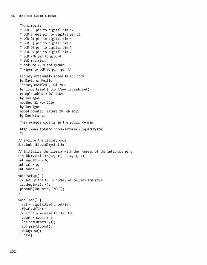
Listing 8-4. Manual Counter Sketch
/* LiquidCrystal Library - Hello World
Demonstrates the use of a 16x2 LCD display. The LiquidCrystal library works with all LCD displays that are compatible with the Hitachi HD44780 driver. There are many of them out there, and you can usually tell them by the 16-pin interface.
This sketch prints "Hello World!" to the LCD and shows the time.
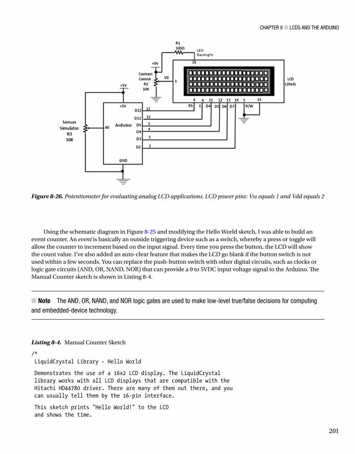
Figure 8-26. Potentiometer for evaluating analog LCD applications. LCD power pins: Vss equals 1 and Vdd equals 2
CHAPTER 8 LCDS AND THE ARDUINO
202
The circuit: * LCD RS pin to digital pin 12 * LCD Enable pin to digital pin 11 * LCD D4 pin to digital pin 5 * LCD D5 pin to digital pin 4 * LCD D6 pin to digital pin 3 * LCD D7 pin to digital pin 2 * LCD R/W pin to ground * 10K resistor: * ends to +5 V and ground * wiper to LCD VO pin (pin 3)
Library originally added 18 Apr 2008 by David A. Mellis library modified 5 Jul 2009 by Limor Fried (http://www.ladyada.net) example added 9 Jul 2009 by Tom Igoe modified 22 Nov 2010 by Tom Igoe added counter feature 20 Feb 2012 by Don Wilcher
This example code is in the public domain.
http://www.arduino.cc/en/Tutorial/LiquidCrystal */
// include the library code:#include <LiquidCrystal.h>
// initialize the library with the numbers of the interface pinsLiquidCrystal lcd(12, 11, 5, 4, 3, 2);int inputPin = 6;int val = 0;int count = 0;
void setup() { // set up the LCD's number of columns and rows: lcd.begin(16, 4); pinMode(inputPin, INPUT);}
void loop() { val = digitalRead(inputPin); if(val==HIGH) { // Print a message to the LCD. count = count + 1; lcd.setCursor(0,3); lcd.print(count); delay(500); } else{

CHAPTER 8 LCDS AND THE ARDUINO
203
lcd.setCursor(0,3); //lcd.print(count); delay(1000); //lcd.setCursor(0,3) count = 0; lcd.clear(); }}
The circuit schematic diagram in Figure 8-26 allows you to test analog sensors such as photocells (CdS cells), FlexiForce resistors, microphones, joysticks, and thermistors. The sketch allows the raw analog data to be displayed on the LCD. I used the potentiometer to test the sketch with success. As I adjusted the potentiometer, the ATmega328 microcontroller’s ADC (analog-to-digital converter) processed the voltage data and displayed the digital values on the LCD. You can easily replace the potentiometer with a light detection circuit to create a cool electronic light-level meter. The Read Sensor sketch is shown in Listing 8-5.
Listing 8-5. Read Sensor Sketch
int sensorPin = A0;int sensorValue = 0;/* LiquidCrystal Library - Read Sensor by Don Wilcher 20 Feb 2012
Demonstrates the use of a 20x4 LCD display. Analog values are displayed on the Liquid Crystal Display based on a change in sensor value.*/
//include the library code:#include <LiquidCrystal.h>
// initialize the library with the numbers of the interface pinsLiquidCrystal lcd(12, 11, 5, 4, 3, 2);
void setup() { pinMode(sensorPin, INPUT); digitalWrite(sensorPin, HIGH); // turns on the internal pull-up resistor lcd.begin(20,4);
}
void loop() { sensorValue = analogRead(sensorPin); lcd.setCursor(0,0); lcd.print("Sensor value = "); lcd.setCursor(0,1); lcd.print(sensorValue); delay(100); sensorValue = 0; lcd.clear();}

CHAPTER 8 LCDS AND THE ARDUINO
204
One last item to explain about the sketch is that the internal pull-up resistor is used instead of an external part. The ATmega328 microcontroller provides this neat feature to save PCB space and cost when designing with the device. Here is the code instruction used for the internal pull-up resistor:
digitalWrite(sensorPin, HIGH); // turns on the internal pull-up resistor
The sketch operates quite nicely. As you change the sensor signal, the LCD updates quickly (in real time). The prototype build of the miniature evaluation board is shown in Figure 8-27.
Figure 8-27. Low-cost proto-evaluation breadboard. The push-button switch and potentiometer allow quick evaluation of the Manual Counter and Read Sensor sketches.
Further Discovery MethodsFor the LCD controllers introduced in this chapter, try experimenting with other kinds of digital and analog sensor circuits. Try replacing the potentiometer for the analog sensor with a joystick or FlexiForce sensor. Modify the Read Sensor sketch to make the message display the Arduino conversion data related to the actual application. Build a temperature controller using a thermistor to measure heat and a small DC motor to cool it when the temperature threshold value is reached. Remember to document your designs in a lab notebook along with any modifications you made to the sketches for the new controllers you’ve created.