learn cisco network administration in a month of … contents 1 before you begin 1 2 what is a cisco...
TRANSCRIPT

SAMPLE CHAPTER
Learn Cisco Network Administration in a Month of Lunches
by Ben Piper
Sample Chapter 2
Copyright 2017 Manning Publications

brief contents1 ■ Before you begin 12 ■ What is a Cisco network? 83 ■ A crash course on Cisco’s Internetwork
Operating System 304 ■ Managing switch ports 465 ■ Securing ports by using the Port Security feature 596 ■ Managing virtual LANs (VLANs) 757 ■ Breaking the VLAN barrier by using switched
virtual interfaces 878 ■ IP address assignment by using Dynamic Host
Configuration Protocol 999 ■ Securing the network by using IP access control lists 115
10 ■ Connecting switches using trunk links 13211 ■ Automatically configuring VLANs using the
VLAN Trunking Protocol 14612 ■ Protecting against bridging loops by using the
Spanning Tree Protocol 15913 ■ Optimizing network performance by using port
channels 17114 ■ Making the network scalable by connecting routers
and switches together 18415 ■ Manually directing traffic using the IP routing table 197
16 ■ A dynamic routing protocols crash course 21317 ■ Tracking down devices 23218 ■ Securing Cisco devices 24319 ■ Facilitating troubleshooting using logging and
debugging 25220 ■ Recovering from disaster 26421 ■ Performance and health checklist 27322 ■ Next steps 280
BRIEF CONTENTS
What is a Cisco network?
Every organization’s most valuable traffic passes through two types of networkingdevices: routers and switches. Cisco makes some of the most popular, dependablerouters and switches around, so most organizations standardize on Cisco for thesedevices. For other networking devices like firewalls and wireless access points, theymay go with Cisco or they may choose a different brand altogether. But as long asthe network uses Cisco routers and switches, you can consider it a Cisco network.
There’s no requirement that you must use Cisco-branded routers and switches.You can use a Cisco switch with a Juniper router, and they’ll work together just fine.You can use a Cisco router with a Juniper switch, and that will work fine too. Butthere are a couple of disadvantages to doing this.
First, the steps to configure a Cisco device are substantially different from thesteps to configure a Juniper device. The commands, terminology, and order inwhich you do things are different. Administering a mixed network requires know-ing how to configure both platforms and getting them to interoperate. This bookaddresses only the Cisco side of things.
Second, if you have a problem on your network and aren’t sure whether it’s therouter or switch, you have to open support tickets with both companies. In theworst case, you get a lot of finger-pointing between the companies. In the best case,you get a delayed resolution.
Mixing different brands of routers and switches isn’t a good idea. That’s why thevast majority of organizations use Cisco for both. It’s just easier. But if you have amixed environment, you can still use this book to learn how to administer the Cisco
8

9The truth about routers and switches
routers or switches on your network. Just be aware that for the purposes of this book, aCisco network always consists of Cisco routers and switches.
In figure 2.1, my computer needs to send an “envelope” containing some data tothe database server. In this chapter, you’re going to learn how the switches and routerensure the data gets to its destination in the most efficient way possible.
2.1 The truth about routers and switchesNewcomers to networking often have two questions:
What do routers and switches actually do? Why do devices have both MAC and IP addresses?
Ben’s computer
Database server
Monoprint
Switch1
Router
Switch2
Colorprint
Ee
Ee
Ee
Ee
Figure 2.1 Switches and a router in a network

10 CHAPTER 2 What is a Cisco network?
These seemingly simple questions don’t have a straightforward answer. I’ve seen manyattempts to answer these questions in a few sentences, and all such attempts invariablycause more confusion than they clear up.
The truth is that routers and switches were born out of necessity rather than practi-cality. In principle, neither device is particularly elegant or clever, although Cisco hasdone some clever things to make them perform better. Like most technologies, rout-ers and switches came about because of questionable decisions that were madedecades ago.
Later technology is usually built on earlier technology. For instance, e-books bor-row concepts such as pages and bookmarks from traditional printed books. Imagineexplaining the page concept to someone who is used to reading scrolls but has neverseen a traditional printed book. How would you do it? Before you can explain what apage is, you have to explain why pages exist in the first place.
Similarly, before I can explain what a router or a switch is, I have to briefly explainwhat problems each was designed to solve. Once you understand that, everything elsewill fall into place more easily, and you’ll be administering your own Cisco network inno time.
2.2 MAC addressesA long time ago, some folks decided that all network devices would uniquely identifyeach other using something called a media access control (MAC) address. A MACaddress is 48 bits long and is represented as a string of hexadecimal numbers, like this:0800.2700.EC26. You’ve probably seen a few of these.
Here’s the interesting part: the manufacturer of each network device assigns it aunique MAC address at the time of manufacture. The rationale behind this is to makeit possible to simply plug a device into a network and have it communicate with otherdevices without having to manually configure anything. That sounds noble, butthere’s a rub: because the manufacturer assigns the MAC address, it has no relation-ship to where the device will physically end up. In that sense, it’s not really an addressbecause it can’t help you locate the device.
A MAC address works like a person’s full name. It’s assigned at birth and makes iteasy to identify someone, get their attention in a crowd of people, and even sendthem a message by calling out their name. If we’re in a large crowd of people, andyou need to communicate a message to me but have no idea where I am, you couldget on a bullhorn and yell, “Ben Piper, where are you?” If I’m in that crowd, I’llreceive your message.
Try it now Open a Windows command shell and type ipconfig /all. Your computer’s MACaddress is listed next to Physical Address. If you have multiple network interfacecards (NICs), you’ll see multiple MAC addresses.

11MAC addresses
Network devices communicate with each other in a similar fashion, but instead ofusing full names, they use MAC addresses. Suppose that my computer has a MACaddress of 0800.2700.EC26, and it needs to print to a network printer named Mono-print with the MAC address 0020.3500.CE26. My computer and the printer have aphysical connection to a device called a switch, as illustrated in figure 2.2. Specifically,my computer and the printer are physically connected to individual Ethernet ports onthe switch. Note that unlike a wireless access point, connections to a switch are alwaysphysical connections. In this sense, a switch is like a gathering place for networkdevices. Just as you and I might gather together with others in a crowded outdoor mar-ketplace, network devices gather together on a switch. This collection of connecteddevices is called a local area network (LAN).
Figure 2.2 Computer and two printers connected to a switch
But here’s the problem: my computer doesn’t know where Monoprint is or if it’s evena part of the LAN—the “crowd” of devices connecting to the switch. MAC addresses, likefull names, make good identifiers, but they’re lousy at telling you exactly where a device is.Because of this, my computer has to get on its “bullhorn” and call out to Monoprintusing its MAC address.
Above and beyondEach device manufacturer has an organizationally unique identifier (OUI), which is astring of six hexadecimal numbers. The OUI makes up the leftmost part of every MACaddress the manufacturer assigns. You can think of the OUI as a person’s surname.Even though it’s assigned “at birth,” devices from the same manufacturer share thesame OUI. The rest of the MAC address is assigned sequentially. This is how manu-facturers ensure each device’s MAC address is unique.
Ben’s computer0800.2700.ec26
Monoprint0020.3500.ce26
Switch1
Colorprint0030.0707.c018
12 CHAPTER 2 What is a Cisco network?
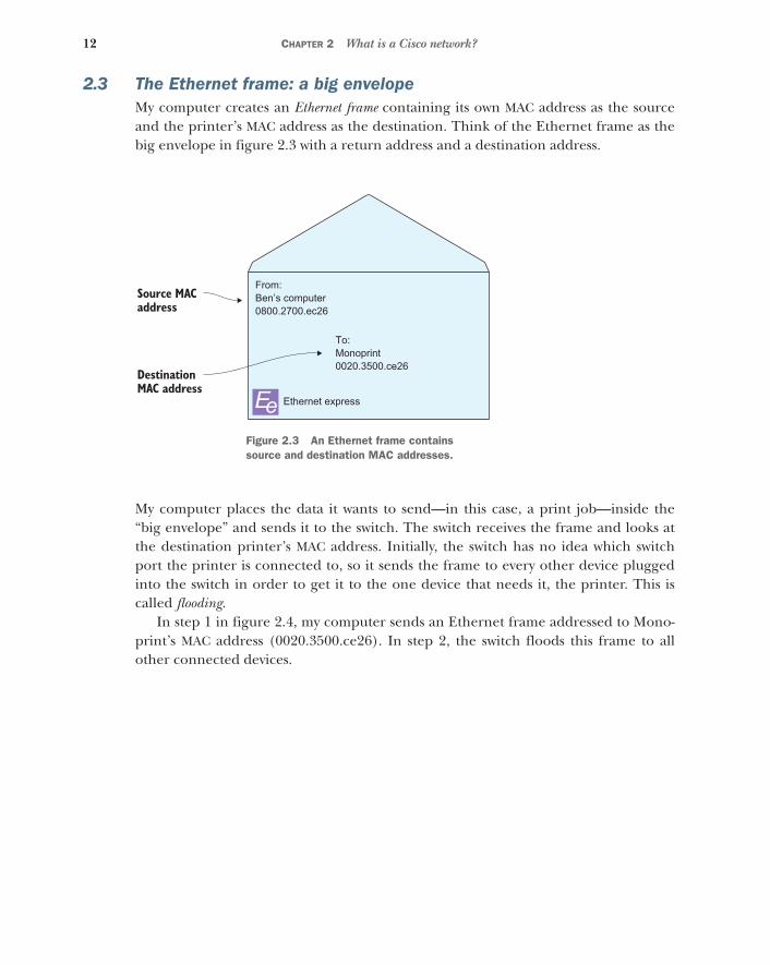
2.3 The Ethernet frame: a big envelopeMy computer creates an Ethernet frame containing its own MAC address as the sourceand the printer’s MAC address as the destination. Think of the Ethernet frame as thebig envelope in figure 2.3 with a return address and a destination address.
My computer places the data it wants to send—in this case, a print job—inside the“big envelope” and sends it to the switch. The switch receives the frame and looks atthe destination printer’s MAC address. Initially, the switch has no idea which switchport the printer is connected to, so it sends the frame to every other device pluggedinto the switch in order to get it to the one device that needs it, the printer. This iscalled flooding.
In step 1 in figure 2.4, my computer sends an Ethernet frame addressed to Mono-print’s MAC address (0020.3500.ce26). In step 2, the switch floods this frame to allother connected devices.
Source MACaddress
DestinationMAC address
Ethernet express
From:Ben’s computer0800.2700.ec26
To:Monoprint0020.3500.ce26
EeFigure 2.3 An Ethernet frame contains source and destination MAC addresses.

13The Ethernet frame: a big envelope
2.3.1 When everybody talks, nobody listens
Flooding has an effect similar to that of blasting a bullhorn into a large crowd. Every-one hears you, but for that moment, people in the crowd can’t hear each other. Youeffectively stop their communication, at least momentarily. Even after you stop bellow-ing into your bullhorn, it takes a bit of time for the people in the crowd to processyour message and realize that they were not the intended recipient. The same thinghappens when a switch floods or sends a message to all devices. Those devices won’tbe able to “hear” any other devices until the flood is over. And even then, they mustprocess the message to determine whether they need to do anything with it. This phe-nomenon is called an interrupt.
Although a few flooded frames and interrupts here and there might seem negligi-ble, consider what would happen in a crowd of, say, 1,000 people who each have abullhorn. Just as you’re ready to get on your bullhorn and send a message to me,someone right next to you gets on their bullhorn and yells out to someone else. Afteryour ears stop ringing, you raise your bullhorn again, only to be once again inter-rupted by someone else. Eventually, you might get enough of a break to get your mes-sage out. But that’s the problem. You’re competing with others for the use of a sharedmedium, the air. This one-to-many communication method makes it difficult to relaya message to a specific person in a timely manner. And the larger the crowd, the worsethe problem becomes.
Ben’s computer0800.2700.ec26
Monoprint0020.3500.ce26
Switch1
1. Ben’s computer sends frame addressed to Monoprint.
2. Switch1 floods frame to all devices.
Colorprint0030.0707.c018
Ee
EeEe
Figure 2.4 Ethernet frame flooding
14 CHAPTER 2 What is a Cisco network?
On a LAN with a few devices, flooding isn’t a problem. On a LAN with hundreds orthousands of devices, it is. But that raises another problem. A network that can’t con-nect thousands of devices is virtually useless.
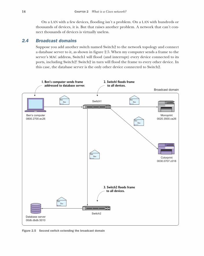
2.4 Broadcast domainsSuppose you add another switch named Switch2 to the network topology and connecta database server to it, as shown in figure 2.5. When my computer sends a frame to theserver’s MAC address, Switch1 will flood (and interrupt) every device connected to itsports, including Switch2! Switch2 in turn will flood the frame to every other device. Inthis case, the database server is the only other device connected to Switch2.
Figure 2.5 Second switch extending the broadcast domain
Ben’s computer0800.2700.ec26
Database server00db.dbdb.5010
Monoprint0020.3500.ce26
Switch1
Broadcast domain
Switch2
Colorprint0030.0707.c018
Ee
Ee
Ee
EeEe
1. Ben’s computer sends frame addressed to database server.
3. Switch2 floods frame to all devices.
2. Switch1 floods frame to all devices.
15Broadcast domains
In step 1, my computer sends a frame addressed to the database server’s MAC address(00db.dbdb.5010). In step 2, Switch1 floods this frame to all of its connected devices.Finally, in step 3, Switch2 floods the frame to the database server.
All of these devices that receive the frame are members of the same broadcastdomain. A broadcast domain isn’t a thing or a directly configurable setting but ratheran emergent property of a network. To better understand this, consider the followinganalogy.
When you stand alone in the middle of a street, you’re not a crowd. But as a fewpeople gather around you, you become part of a small crowd. As more people gatheraround you, you become part of a larger crowd. You don’t change, but you becomepart of a crowd by virtue of how many others gather around you. Similarly, a devicebecomes part of a broadcast domain by virtue of which devices it receives floodedframes from.
2.4.1 Closing the floodgates: the MAC address table
Flooding is an inevitable side effect of using MAC addresses. Fortunately, switches usea neat little trick to mitigate unnecessary flooding. Whenever a switch receives aframe, it looks at the source MAC address and the switch port it came in on. It uses thisinformation to build a MAC address table.
When Switch1 receives a frame from my computer, it takes note of the source MACaddress—0800.2700.ec26—as well as the switch port the frame came in on—FastEthernet0/1. It adds this information to its MAC address table, as shown in table 2.1.
Now suppose the database server sends a frame addressed to my computer’s MACaddress. The frame reaches Switch2, which in turn forwards it to Switch1. But thistime, instead of blindly flooding the frame to all other devices, Switch1 checks its MACaddress table.
Above and beyondCisco sometimes refers to the MAC address table as a content addressable memory(CAM) table, but they’re the same thing.
Table 2.1 Switch1’s MAC address table
Device MAC address Switch port
Ben’s computer 0800.2700.ec26 FastEthernet0/1

16 CHAPTER 2 What is a Cisco network?
It sees that the destination MAC address—0800.2700.ec26—is on FastEthernet0/1,so it sends that frame only out of that specific port; see figure 2.6. This works similarlyto an old telephone switchboard, which is where the term switch comes from.
Figure 2.6 How the MAC address table mitigates flooding
In step 1, the database server sends a frame to my computer’s MAC address(0800.2700.ec26). In step 2, Switch2 floods the frame to Switch1. In step 3, Switch1consults its MAC address table and finds a corresponding entry for the destinationMAC. In step 4, Switch1 sends the frame only to my computer instead of flooding it toall devices.
Ben’s computer0800.2700.ec26
Database server00db.dbdb.5010
Monoprint0020.3500.ce26
Switch1
Broadcast domain
1. Database server sends frame addressed to Ben’s computer.
Switch2
Colorprint0030.0707.c018
Ee
4. Switch1 sends frame only to Ben’s computer.
3. Switch1 checks MAC address table.
Ee
2. Switch2 floods frame to Switch1.
Ee

17Broadcast domains
2.4.2 Breaking up the broadcast domain
As the size of the broadcast domain grows, communication becomes more difficult.Consequently, a broadcast domain containing hundreds of devices performs poorly. Butmodern organizations require network connectivity among thousands of devices. Andjust having connectivity isn’t good enough. The network still has to be fast and reliable.
The solution is to limit the size of the broadcast domain. This means breaking it intomultiple, small broadcast domains that somehow can still communicate with each other.
Going back to our example, the simplest way to split the broadcast domain is toremove the Ethernet cable connecting Switch1 and Switch2, as shown in figure 2.7.Note that the switches aren’t connected in any way. That’s the easy part. Here’s thehard part: My computer and the database server reside on two separate broadcastdomains. There’s no way my computer and the server can communicate. What do youdo? You can’t just plug the switches back together because that would re-create theoriginal, single broadcast domain.
Figure 2.7 Two broadcast domains
Ben’s computer0800.2700.ec26
Database server00db.dbdb.5010
Monoprint0020.3500.ce26
Switch1
Broadcast domain 1
Broadcast domain 2
Switch2
Colorprint0030.0707.c018
Ee
EeEe

18 CHAPTER 2 What is a Cisco network?
2.4.3 Joining broadcast domains
In order to join two broadcast domains together without encountering that nastyflooding problem, two things must happen: First, because both broadcast domains arephysically disconnected, you need a special device to physically connect them in sucha way that flooded frames can’t cross the broadcast domain boundary. Because framescontain source and destination MAC addresses, this device will effectively hide theMAC addresses in one broadcast domain from the MAC addresses in the other.
Second, because MAC addresses in one broadcast domain will be hidden from thosein another, you need a different scheme to address devices across multiple broadcastdomains. This new addressing scheme, unlike MAC addresses, must not only be able touniquely identify devices across broadcast domains, but it must also provide some cluesas to which broadcast domain each device resides in. Let’s start with the latter.
2.4.4 Addressing devices across broadcast domains
The addressing scheme has to meet some requirements: First, the addresses have tobe unique across broadcast domains. A device in one broadcast domain can’t have thesame address as another device. Second, the address has to tell us all by itself whichbroadcast domain it’s a part of. The address should be able to not only uniquely identify adevice but also tell other devices which broadcast domain it resides in. This is to avoid that uglyflooding problem. Third, the addresses can’t be “assigned at birth” like MACaddresses. They have to be configurable by you, the network administrator.
Fortunately, you don’t have to look very far. Such an addressing scheme alreadyexists, and you’re already using it.
2.5 Internet Protocol addressesYou already know what an IP address looks like. One of the most common IP addressesis 192.168.1.1. It’s a series of four octets separated by dots, and each octet can rangefrom 0 to 255.
You’ve probably seen these 192.168.x.x addresses pop up in a variety of places.That’s because 192.168.x.x addresses are reserved for use on private networks likeyour home or business. They’re not globally unique because they’re not reachable viathe public internet. But you can still use them to address devices on your own internalnetworks.
Unlike a MAC address, you can assign any IP address to whatever device you like.You can create your own addressing scheme based on where devices are, not just whatthey are. Let’s look at an example.
2.5.1 Where are you?
Devices connected to Switch1 are in broadcast domain 1 and devices connected toSwitch2 are in broadcast domain 2. You could, then, assign a 192.168.1.x address to alldevices connected to Switch1 and a 192.168.2.x address to devices connected toSwitch2. Even without looking at figure 2.8, just knowing the IP addresses makes itpainfully obvious which broadcast domain each device resides in.

19Internet Protocol addresses
Figure 2.8 Each device has an IP address that corresponds to its broadcast domain.
But at this point, there’s still no connectivity between the two broadcast domains, soit’s only possible for devices to communicate within the same broadcast domain. Butthat raises this question: Now that each device has both an IP and MAC address, whichone will it use to communicate within its broadcast domain?
Above and beyondNote that if you wanted to add a third broadcast domain, you could assign192.168.3.x addresses to the devices in that domain. The nice thing about using IPaddresses is that there’s no practical limit to the number of separate broadcastdomains you can address with them.
Ben’s computer0800.2700.ec26
192.168.1.10
Database server00db.dbdb.5010
192.168.2.70
Monoprint0020.3500.ce26
192.168.1.20
Switch1
Broadcast domain 1
Broadcast domain 2
Switch2
Colorprint0030.0707.c018
192.168.1.21
Ee
EeEe

20 CHAPTER 2 What is a Cisco network?
2.5.2 The IP vs. MAC dilemma
“Why don’t we just use IP addresses instead of MAC addresses?” is a common refrainamong IT professionals trying to learn networking. It’s a good question.
After all, MAC addresses aren’t very friendly. They’re hard to remember, mostlymeaningless, and difficult (if not impossible) to change. IP addresses, on the otherhand, are easy to remember, easy to change, and can be very meaningful with regardto location and function. The winner here is obvious.
So why don’t we just use IP addresses and get rid of MAC addresses altogether? Theanswer is simple but a bit disturbing.
Network devices within a broadcast domain still have to communicate using MACaddresses. This is a requirement of the Ethernet standard that’s been around fordecades. Assigning IP addresses doesn’t change that. Sure, someone could comealong and create a new standard that makes MAC addresses unnecessary, but thatwould require replacing every single device on your network.
In short, MAC addresses are here to stay. That’s the bad news. The good news isthat you don’t have to think about them, at least not very often.
2.5.3 Address Resolution Protocol
Remembering both the MAC and IP address of a device is inefficient and wasteful.That’s why almost all networked applications use the IP address and completely ignorethe MAC address. The Address Resolution Protocol (ARP) makes this possible.
ARP provides a clever way to map or resolve IP addresses to MAC addresses. Theadvantage of ARP is that it lets you use human-friendly IP addresses without even hav-ing to think about MAC addresses. All network devices made since the mid-1980s useARP by default, so you don’t need to manually configure it.
Suppose that my computer needs to send another print job to Monoprint. Bothdevices are in the same broadcast domain, so they’re still going to talk using their MACaddresses. But you, as a network administrator, don’t want to even think about MACaddresses. So you configure my computer to print to Monoprint’s IP address:192.168.1.20.
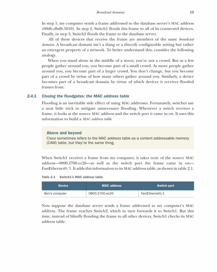
Figure 2.9 illustrates how ARP works. My computer sends an ARP request to figureout Monoprint’s MAC address. The request says, “This is 192.168.1.10 and my MACaddress is 0800.2700.EC26. Who has 192.168.1.20?” My computer stuffs this ARPrequest inside an Ethernet frame and sends it to a special broadcast MAC address,FFFF.FFFF.FFFF, as shown in figure 2.9.
Remember that all network devices must use MAC addresses to communicate. Inorder for my computer to get the ARP request to all devices on the network, it has toaddress the Ethernet frame to some MAC address. It can’t send it to a blank address. Soit sends the ARP request to the broadcast MAC address. Each device listens for thebroadcast address in addition to listening for its own MAC address. This ensures thatevery device on the network pays attention to every ARP request.
In step 1, my computer sends an ARP request to the broadcast MAC address(FFFF.FFFF.FFFF). In step 2, Monoprint sends back an ARP reply containing its IP
21Connecting broadcast domains using a router
address (192.168.1.20). Finally, in step 3, my computer sends the print job to Mono-print’s MAC address.
The switch floods this frame out all ports, including the port Monoprint is con-nected to. Monoprint receives the frame, peeks inside, and sees the ARP request.Monoprint sees the query “Who has 192.168.1.20?” and thinks, “Oh, that’s my IPaddress!” Monoprint then sends an ARP reply back to my computer: “This is192.168.1.20. My MAC address is 0020.3500.CE26.” Bingo. My computer now knowsMonoprint’s MAC address and will communicate with it using that.
ARP is the secret sauce that rescues you from having to think about MAC addressesvery much. It frees you up to think in terms of friendly, meaningful IP addresses thevast majority of the time.
2.6 Connecting broadcast domains using a routerNow that you’re free to think in terms of IP addresses, it’s time to learn how devicesuse them to communicate across broadcast domains.
At this point you have two separate broadcast domains with no connectivitybetween them. In order to join the two broadcast domains together without re-creatinga single broadcast domain, you need a special device called a router. A router physicallyconnects broadcast domains in such a way that frames can’t cross the broadcastdomain boundary. Because frames are what contain source and destination MACaddresses, the router effectively hides the MAC addresses in one broadcast domainfrom the MAC addresses in the other.
Ben’s computer0800.2700.ec26
192.168.1.10
From: 0800.2700.ec26To: FFFF.FFFF.FFFF
“This is 192.168.1.10.Who has 192.168.1.20?” Monoprint
0020.3500.ce26192.168.1.20
1. Ben’s computer sends request to broadcast MAC address
From: 0200.3500.ce26To: 0800.2700.ec26
“I have 192.168.1.20!”
2. Monoprint sends reply containing IP address
From: 0800.2700.ec26To: 0020.3500.ce26
“Print this!”
3. Ben’s computer sends print job to Monoprint’s MAC
Figure 2.9 Address Resolution Protocol request and reply

22 CHAPTER 2 What is a Cisco network?
In figure 2.10, the router physically sits on both broadcast domains. It has at least twoports or interfaces, one to connect to each broadcast domain. Each network interfaceon a router has its own unique MAC address. Keep in mind that each interface on therouter has a unique MAC address only for the purpose of being compatible with the Eth-ernet standard that all the other devices on the network use. Just like e-books still use“pages,” routers use MAC addresses for backward compatibility. Not only does therouter have two MAC addresses, but it also has two IP addresses. On the interface con-necting to Switch1, the router has an IP address of 192.168.1.254. On the interface con-necting to Switch2, the router has an IP address of 192.168.2.254. Again, these areunique IP addresses, and the third octet (1 or 2) corresponds to the broadcast domain.
Ben’s computer0800.2700.ec26
192.168.1.10
Database server00db.dbdb.5010
192.168.2.70
Monoprint0020.3500.ce26
192.168.1.20
Switch1
Broadcast domain 1
Broadcast domain 2
192.168.2.2540073.37c1.5c02
Router
Ethernet frames donot cross the broadcastdomain boundary.
Router’s IP andMAC addresses inbroadcast domain 2
Switch2
Colorprint0030.0707.c018
192.168.1.21
Ee
Ee
EeEe
192.168.1.2540073.37c1.5c01
Router’s IP andMAC addresses inbroadcast domain 1
Figure 2.10 A router connecting two broadcast domains. The router has a unique IP and MAC address for each broadcast domain. Notice that Ethernet frames do not traverse the broadcast domain boundary.

23Connecting broadcast domains using a router
2.6.1 Where are you? Where am I?
My computer has an IP address of 192.168.1.10 and resides in broadcast domain 1. Adatabase server with an IP address of 192.168.2.70 resides in broadcast domain 2. Thesignificance of these addresses is obvious to a person. Devices with 192.168.1.xaddresses are in broadcast domain 1, and those with 192.168.2.x addresses are inbroadcast domain 2.
But my computer doesn’t know that. Computers are, after all, just dumb machinesthat do what we tell them. So my computer needs some way to know which broadcastdomain it’s in. Once it knows that, it will be able to figure out whether another deviceis in the same broadcast domain or a different one.
2.6.2 Understanding subnets
In reality, broadcast domains aren’t given numbers because they’re not real things.But associating a set of IP addresses with a broadcast domain makes the abstract ideaof a broadcast domain a lot easier to think about and work with. The set of addressesthat corresponds to a broadcast domain is called a subnetwork, or subnet for short.
Take the 192.168.1.x subnet, for example. When you think about it, there’s noth-ing about this address that says, “All addresses from 192.168.1.1 to 192.168.1.255 arein the same broadcast domain!” Even if you were already thinking that, you probablygot that idea from this chapter and not just from looking at the address. But my com-puter can’t read and comprehend as humans can, so you need a more explicit way oftelling it which broadcast domain it’s in.
To do this, you use a subnet mask. The subnet mask is an additional quartet ofoctets, formatted like an IP address, that indicates which IP addresses are inside thebroadcast domain and which are outside.
As you can see in figure 2.11, my computer has an IP address of 192.168.1.10 and asubnet mask of 255.255.255.0. Line the two up as shown in table 2.2 and compare
Figure 2.11 Output from ipconfig showing my computer’s IP information

24 CHAPTER 2 What is a Cisco network?
each octet. A 255 in the subnet mask indicates that another IP with the same octet is inthe same broadcast domain. A 0 in the subnet mask indicates that the correspondingoctet has no bearing on the broadcast domain.
My computer’s IP address and subnet mask are useless by themselves. The question athand is whether 192.168.2.70 is in the same broadcast domain as my computer. Let’splug in that IP address and find out, as shown in table 2.3.
The first two octets match, but the third octet is different. And because the subnetmask for that octet is 255, my computer knows that the database server is in a differentbroadcast domain. So in order to get across to the database server, it has to traversethe router. But before it can use the router, it has to know that the router exists andhow to reach it.
2.7 Traversing broadcast domains using a default gatewayNow that my computer has done the hard work of figuring out that the databaseserver is on a different broadcast domain, it needs to know which router to use to con-nect to the database server. For this, it checks its default gateway address.
My computer has a default gateway address of 192.168.1.254. This corresponds tothe IP address of the router’s interface that sits in broadcast domain 1. Based on thedefault gateway address, my computer knows that when it needs to send anything toan IP address outside its own broadcast domain, it must relay that message throughthe router.
Table 2.2 Determining the broadcast domain based on the IP address and subnet mask
My computer’s IP address 192 168 1 10
Subnet mask 255 255 255 0
Table 2.3 The database server’s IP address is in a different subnet than my computer’s IP address.
My computer’s IP address 192 168 1 10
Subnet mask 255 255 255 0
Database server’s IP address 192 168 2 70
Try it now Open a Windows command shell and type ipconfig. Note the IP address and sub-net mask. Think of a different IP address that you know your organization uses. Deter-mine whether it’s in the same broadcast domain as your machine.

25Traversing broadcast domains using a default gateway
My computer sends an ARP request for 192.168.1.254, and the router responds with itsown MAC address of 0073.37c1.5c01. My computer puts together an Ethernet frameaddressed to the router’s MAC address. But this time it also puts together a smallerenvelope called an IP packet. If an Ethernet frame is a large envelope with MACaddresses, an IP packet is a smaller envelope with source and destination IP addresses.
The IP packet contains my computer’s IP address, 192.168.1.10, as the source andthe server’s address, 192.168.2.70, as the destination. Figure 2.12 illustrates my com-puter stuffing this smaller envelope—the IP packet—into the larger envelope—theEthernet frame, which, again, has the router’s MAC address as the destination. Thisprocess of “stuffing the Ethernet envelope” is called encapsulation.
Figure 2.12 IP packet being encapsulated in an Ethernet frame
My computer sends the Ethernet frame containing the IP packet off to the router. Therouter receives the Ethernet frame, pulls out the IP packet, and sees the IP packet’sdestination—192.168.2.70. The router recognizes that 192.168.2.70 is in the samebroadcast domain as the interface connected to broadcast domain 2.
The router then sends an ARP request for the server’s IP address, 192.168.2.70. TheARP request says, “This is 192.168.2.254. Who has 192.168.2.70?” The server responds
Above and beyondNote that my computer’s IP address—192.168.1.10—and the default gateway IPaddress are in the same subnet. This is really important. If a device isn’t on the samebroadcast domain and subnet as its router, that device can’t reach any devices out-side its broadcast domain.
Ethernet express
From:Ben’s computer0800.2700.ec26
To:Router0073.37c1.5c01
Ee
To:Database server192.168.2.70
IP expressIPe
From:Ben’s computer192.168.1.10

26 CHAPTER 2 What is a Cisco network?
with its MAC address, and the router takes the IP packet and tucks it inside a new Eth-ernet frame addressed to the server’s MAC address, as shown in figure 2.13.
In step 1, the router removes (decapsulates) the IP packet from the original frame.In step 2, the router re-encapsulates the packet in a new frame addressed to the data-base server.
Notice that the IP packet itself never changes during this process. The router preservesboth the source and destination IP addresses but changes only the MAC addresses onthe Ethernet frames. The router then sends this new Ethernet frame to the server.The server receives it, takes out the IP packet, and says, “Hey! I’m 192.168.2.70! Thispacket is meant for me.”
Ethernet express
From:Router0073.37c1.5c02
To:Database server00db.dbdb.5010
Ee
Ethernet express
From:Ben’s computer0800.2700.ec26
To:Router0073.37c1.5c01
Ee
To:Database server192.168.2.70
IP expressIPe
From:Ben’s computer192.168.1.10
1. Router decapsulates IP packet from original frame
2. Router re-encapsulates IP packet in new frame addressed to database
Figure 2.13 Router re-encapsulating the IP packet from my computer

27Traversing broadcast domains using a default gateway
Figure 2.14 Using a router to traverse broadcast domains
Figure 2.14 illustrates how the router gets the IP packet across the broadcast domainboundary while hiding the MAC addresses in one broadcast domain from the devicesin the other. This process is called IP routing.
In step 1, my computer sends an ARP request to get the router’s MAC address. Instep 2, the router sends an ARP reply containing its IP address. In step 3, my computersends a frame addressed to the router’s MAC address (0073.37c1.5c01). The framecontains an IP packet addressed to the database server (192.168.2.70). In step 4, therouter sends an ARP request to get the database server’s MAC address. In step 5, thedatabase server sends an ARP reply. Finally, in step 6, the router sends a frame
Database server00db.dbdb.5010
192.168.2.70
From: 0073.37c1.5c02To: FFFF.FFFF.FFFF
“This is 192.168.2.254.Who has 192.168.2.70?”
From: 00db.dbdb.5010To: 0073.37c1.5c02
“I have 192.168.2.70!”
Broadcast domain 1
Router
Ee
Ben’s computer0800.2700.ec26
192.168.1.10
From: 0800.2700.ec26To: FFFF.FFFF.FFFF
“This is 192.168.1.10.Who has 192.168.1.254?”
1. Ben’s computer sends request for router’s MAC address
2. Router replies with its IP address
3. Ben’s computer sends frame to router’s MAC
4. Router sends request for database server’s MAC
5. Database server replies
6. Router sends frame with original packet to Database server’s MAC
From: 0073.37c1.5c01To: 0800.2700.ec26
“I have 192.168.1.254!”
From: 0800.2700.ec26To: 0073.37c1.5c01
Broadcast domain 2
Ee
From: 0073.37c1.5c02To: 00db.dbdb.5010

28 CHAPTER 2 What is a Cisco network?
addressed to the database server’s MAC address (00db.dbdb.5010) containing theoriginal IP packet.
Now it’s time to put it all together. Figure 2.15 shows how the IP packet from mycomputer gets all the way to the database server without any unnecessary flooding.
In step 1, my computer encapsulates an IP packet in a frame addressed to therouter. It sends the frame to Switch1, which forwards it to Switch2. In step 2, therouter removes the IP packet, looks at the destination IP address, and re-encapsulatesit in a new frame addressed to the database server. In step 3, the router sends the newframe to Switch2, which forwards it to the database server.
Ben’s computer0800.2700.ec26
192.168.1.10
Database server00db.dbdb.5010
192.168.2.70
Monoprint0020.3500.ce26
192.168.1.20
Switch1
Broadcast domain 1
Broadcast domain 2
Router
2. Router takes out IP packet and re-encapsulates it in a new frame
Switch2
Colorprint0030.0707.c018
192.168.1.21
Ee
Ee
Ee
Ee
Ee
Ee
IPe
192.168.2.2540073.37c1.5c02
192.168.1.2540073.37c1.5c01
3. Router sends frame addressed to database server (00db.dbdb.5010)
1. Ben’s computer sends frame addressed to router (0073.37c1.5c01)
Figure 2.15 Using routing and switching to get an IP packet from one broadcast domain to another without unnecessary flooding
29Hands-on lab
2.8 Managing routers and switchesAt this point, you should have a basic understanding of the roles routers and switchesplay. You’re probably anxious to get your hands on these devices and start pokingaround and configuring them. But before you can do that, you need to actually getaccess to them.
Routers have their own IP addresses, but switches can have them too. You’ll typi-cally find a special management IP address assigned to each router and switch on anetwork. The management IP address allows you to administer these devices remotelywithout having to physically walk up to the device and plug into the serial consoleport. Your organization’s routers and switches are likely locked in a closet or data cen-ter facility somewhere, and even if you have physical access to them, configuring themin person is a pain. That’s why you need to obtain the management IP addresses andlogin credentials for each device you might need to administer. Be sure to do thisbefore tomorrow’s lesson.
2.9 Hands-on labDownload the inventory worksheet from the Source Code link at https://www.manning.com/books/learn-cisco-network-administration-in-a-month-of-lunches. Obtain themanagement IP addresses of all routers and switches on your network (or lab) andrecord them. Also obtain the login credentials (usernames and passwords) for logginginto each of these devices.
On your computer, open an administrative command prompt or terminal. Get theMAC address, IP address, and default gateway of your computer with ipconfig /all.Type arp –a and get the MAC address of the default gateway. Record this informationin the inventory worksheet.
