lect.no.9-first semester channel design...2-design of unlined channels the sides and bottoms of...
TRANSCRIPT

Water and Hydraulics Structures Branch / 3rd Class [Hydraulic Structures]
Lect.No.9-First Semester Channel Design
Asst. Prof. Dr. Jaafar S. Maatooq 1 of 12
Open channels are designed to carry a design discharge in a safe and economical
way.
** For water distribution channels, such as those used in irrigation and water supply
projects, the design discharge is determined on the basis of total delivery
requirements.
Open channels are usually designed for uniform or normal flow conditions.
Designing an open channel involves the selection of:-
- Channel alignment,
- Size and shape,
- Longitudinal slope, and
- The type of lining material.
Normally, the designer considered several hydraulically feasible alternatives, and
compare them to determine the most cost-effective alternative. This lecture will
emphasize the hydraulic considerations involved in channel design rather than
economic analyses of different alternatives.
1-GENERAL DESIGN CONSIDERATIONS
** Selection of channel alignment;
It is the first step in designing an open channel. Generally, the topography of the
area, existing and planned adjacent structures and transportation facilities control
the channel alignment. The topography also controls the invert elevations and
bottom slope of the channel.
** Cross-sectional shape and size;
Most manmade surface channels are trapezoidal in cross-section, although
triangular, parabolic and rectangular channels are also used. The hydraulic capacity
is a main factor to accommodate the design discharge. There are, however, other
factors to be considered, these are:-
Water and Hydraulics Structures Branch / 3rd Class [Hydraulic Structures]
Lect.No.9-First Semester Channel Design
Asst. Prof. Dr. Jaafar S. Maatooq 2 of 12
- the depth of the channel may be limited due to a high water table in the
underlying soil.
- channel widths and side slopes, where;
* large channel width and mild side slope will result in high costs of crossing ways
and structures such as bridges and regulators.
* Small channel widths, on the other hand, may create construction difficulties.
Likewise, steep side slopes can cause slope stability problems as well as high
erosion rates in earthen channels.
** Flow conditions;
Mostly open channels are designed for subcritical flow (Fr˂1). The design
discharge is only a single estimated value; the actual discharge occurring in a
channel will vary possibly above and below the design discharge.
** State of Boundary;
Channels are often lined to prevent the sides and the bottom of the channel from
suffering erosion due to the shear stresses caused by the flow. The types of channel
linings can be categorized into two broad groups:
- Rigid
- Flexible.
* Rigid lining materials include;
- cast-in-place concrete,
- cast-in-place asphaltic concrete,
- stone masonry,
- soil cement, and
- grouted riprap.
Rigid linings can:-
- resist high shear stresses and provide a much higher conveyance capacity for the
same cross-sectional size and channel slope,
- reduce losses of water from the channel due to seepage.
The disadvantage of rigid lining is it susceptible to failure from structural instability
caused by freeze-thaw, swelling, and excessive soil pore pressures.

Water and Hydraulics Structures Branch / 3rd Class [Hydraulic Structures]
Lect.No.9-First Semester Channel Design
Asst. Prof. Dr. Jaafar S. Maatooq 3 of 12
When a rigid lining deteriorates, large broken slabs may be dislodged and displaced
by the channel flow, resulting in significant erosion problems and slope and
structure failures.
*Flexible linings can be further classified into:
- Permanent, and
- Temporary linings.
Permanent flexible linings include;
- riprap,
- vegetation lining, and
- gravel.
* Temporary linings are used for temporary protection against erosion until
vegetation is established. It include synthetic mat. Flexible linings have several
advantages compared to rigid linings these are:
- less susceptible to structural failure, because they can conform to the changes in
the channel shape.
- allow infiltration.
The disadvantages of flexible linings are:
- It can only sustain limited magnitudes of erosive forces.
- To accommodate the same design discharge safely, a channel section with a
flexible lining would have to be considerably larger than a section lined with a rigid
material. Therefore, flexible lining can lead to higher overall channel costs although
the flexible lining materials are usually less expensive than the rigid lining materials
in terms of construction costs.
** Freeboard;
Is the vertical distance between the top of the channel and the water surface that
prevails under the design flow conditions. This distance should be sufficient to
allow variations in the water surface due to wind-driven waves, tidal action,
occurrence of flows exceeding the design discharge, and other causes. There are no
universally accepted rules to determine a freeboard. In practice, freeboard selection
is often a matter of judgment, or it is stipulated as part of the prevailing design
standards. For preliminary estimates, the US Bureau of Reclamation (Chow, 1959)
recommends that the unlined channel freeboard be computed as:

Water and Hydraulics Structures Branch / 3rd Class [Hydraulic Structures]
Lect.No.9-First Semester Channel Design
Asst. Prof. Dr. Jaafar S. Maatooq 4 of 12
…………………………………………. (1)
Where F=freeboard, y=flow depth, and C=a coefficient depends on system of units;
C=1.5ft - 2.5ft (for channel capacity ranged between 20 - 3000 ft3/s)
C=0.5m - 0.76m (for channel capacity ranged between 0.6 - 85m3/s)
Linear interpolation is acceptable to determine the intermediate values of C. For
lined channels, the curves displayed in Fig.(L9-1) can be used to estimate the height
of bank above water surface and the height of lining above water surface. This
figure follows the US Bureau of Reclamation recommendations.
Fig.(L9-1): Suggested heights of lining and bank above water surface
Water and Hydraulics Structures Branch / 3rd Class [Hydraulic Structures]
Lect.No.9-First Semester Channel Design
Asst. Prof. Dr. Jaafar S. Maatooq 5 of 12
2-DESIGN OF UNLINED CHANNELS
The sides and bottoms of earthen channels are both erodible. The main criterion for
earthen channel design is that the channel is not eroded under the design flow
conditions. There are two approaches to erodible channel design;
- The maximum permissible velocity method and
- The tractive force method.
(A): Maximum Permissible Velocity Method
This method is based on the assumption that a channel will not be eroded if the
average cross-sectional velocity in the channel does not exceed the maximum
permissible velocity. The magnitude of the maximum permissible velocity depends
on the type of channel boundary material as well as the channel alignment. The
maximum permissible velocities presented in Table (L9-2). These values are
usually considered to be valid for straight channels having a flow depth of up to 3 ft
or 1 m. The values given in Table 5.2 can be reduced by:
* 13% for moderately sinuous channels and
* 22% for very sinuous channels.
Also, for flow depths exceeding 3 ft or 1 m, the maximum permissible velocities
can be increased by about 0.50 fps or 0.15 m/s.
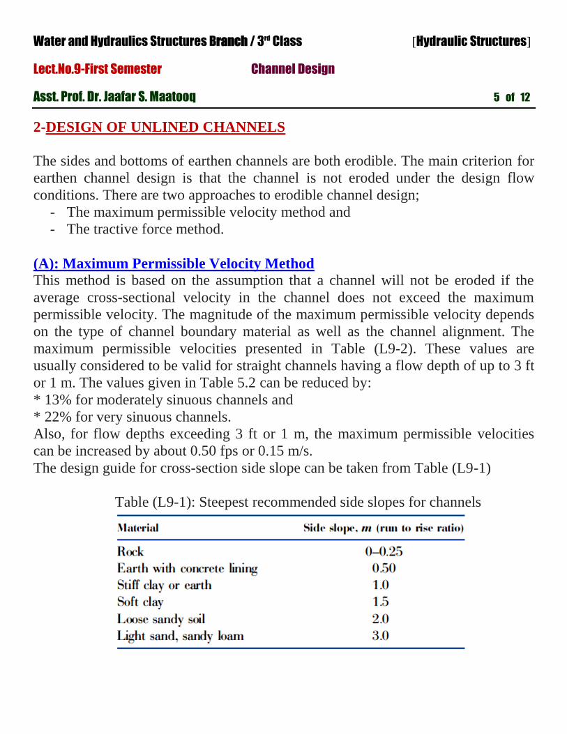
The design guide for cross-section side slope can be taken from Table (L9-1)
Table (L9-1): Steepest recommended side slopes for channels

Water and Hydraulics Structures Branch / 3rd Class [Hydraulic Structures]
Lect.No.9-First Semester Channel Design
Asst. Prof. Dr. Jaafar S. Maatooq 6 of 12
Table (L9-2): Suggested maximum permissible channel velocities
In a typical problem, the solution regarding sizing a channel section, it should know
firstly;
- the channel bottom slope, S0,
- the design discharge, Q, and
- the type of the channel material. The procedure to design the size the channel
section according to max. permissible velocity method consists of the following
steps:
1. For the specified channel material, determine the Manning roughness factor “n”,
the side slope m from Table (L9-1), and the maximum permissible velocity “VMAX”
from Table (L9-2).
2. Compute the corresponding hydraulic radius, R, from the Manning formula.
3. Compute the required flow area as A=Q/VMAX.
4. Compute the wetted perimeter as P=A/R.

Water and Hydraulics Structures Branch / 3rd Class [Hydraulic Structures]
Lect.No.9-First Semester Channel Design
Asst. Prof. Dr. Jaafar S. Maatooq 7 of 12
5. Knowing the magnitudes of “A” and “P” and using the geometrical expressions
for A and P, solve for the flow depth “y” and the bottom width “b” simultaneously.
6. Check the Froude number to ensure that it is not close to the critical value of 1.0.
7. Add a freeboard and modify the section for practical purposes.
Step (5) of this procedure requires the solution of two simultaneous equations. This
can be facilitated for trapezoidal channels by using the following equations:
………………………………. (2)
……………………………………. (3)
………………………………….. (4)
Where W is an intermediate dimensionless parameter.
(B): Tractive Force Method
The forces acting on the soil particles comprising the channel bottom and sides are
considered in this method. Flow in a channel exerts tractive forces (or shear forces)
on the channel bed that are equal in magnitude but opposite in direction to the
friction forces exerted by the channel bed on the flow.
** The tractive forces tend to move the particles on the channel bed in the flow
direction.
** Erosion will occur if the tractive forces exceed the resistive forces preventing the
movement of these particles.

Water and Hydraulics Structures Branch / 3rd Class [Hydraulic Structures]
Lect.No.9-First Semester Channel Design
Asst. Prof. Dr. Jaafar S. Maatooq 8 of 12
The design of an earthen channel, must proportion the channel section so that the
particles will not move under the design flow conditions.
Flow Mechanism
The flow-induced tractive forces are tending to move the soil particles lying
on the channel bottom and on the sides of the channel as well.
The particles on the sides of the channel tend to roll down the slope due to the
effect of gravity. Therefore, the forces tending to move the particles on the
sides of a channel are the resultant of the flow-induced tractive forces and the
gravitational forces acting on the soil particles.
For cohesive soils, the gravitational forces are much smaller than the cohesive
forces keeping the soil particles together.
For design purposes, the forces acting on unit areas on the channel bottom and
sides are considered rather than individual soil particles.
For normal flow, the flow-induced average unit tractive force, or the average
tractive force per unit area over the channel perimeter, is equal to γRS0 where
γ =specific weight of water, R=hydraulic radius, and S0=bottom slope of the
channel.
The distribution of the unit tractive force over the channel perimeter is non-
uniform, as shown in Figure (L9-2).
Defining τb=maximum unit tractive force on the channel bottom, and,
τs0=maximum unit tractive force on the sides, Lane (1955), has been express τb and
τs0 in terms of the flow depth as;
…………………………………. (5)
…………………………………. (6)
Water and Hydraulics Structures Branch / 3rd Class [Hydraulic Structures]
Lect.No.9-First Semester Channel Design
Asst. Prof. Dr. Jaafar S. Maatooq 9 of 12
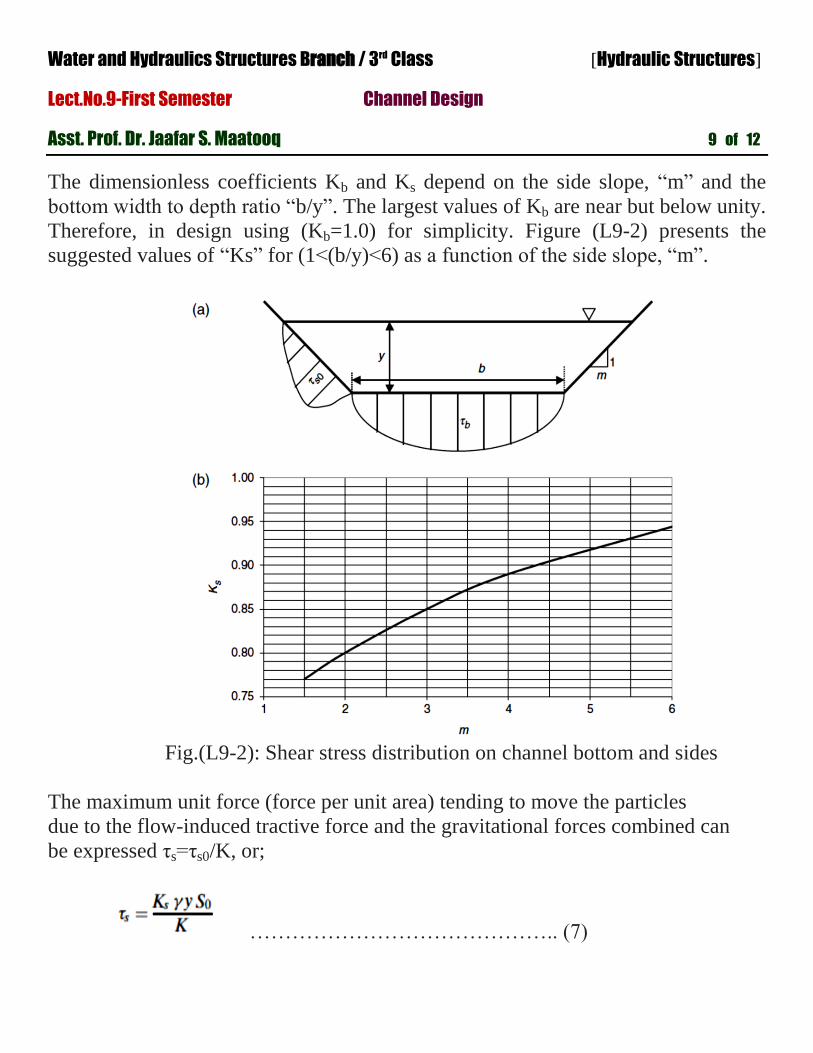
The dimensionless coefficients Kb and Ks depend on the side slope, “m” and the
bottom width to depth ratio “b/y”. The largest values of Kb are near but below unity.
Therefore, in design using (Kb=1.0) for simplicity. Figure (L9-2) presents the
suggested values of “Ks” for (1˂(b/y)˂6) as a function of the side slope, “m”.
Fig.(L9-2): Shear stress distribution on channel bottom and sides
The maximum unit force (force per unit area) tending to move the particles
due to the flow-induced tractive force and the gravitational forces combined can
be expressed τs=τs0/K, or;
…………………………………….. (7)
Water and Hydraulics Structures Branch / 3rd Class [Hydraulic Structures]
Lect.No.9-First Semester Channel Design
Asst. Prof. Dr. Jaafar S. Maatooq 10 of 12
τs=maximum unit force tending to move the particles, and K=tractive force ratio; it
is a dimensionless parameter reflecting the tendency of soil particles to roll down
the side slopes due to gravity.
For cohesive soils, K=1.0 (that is refer the effect of the gravitational forces is
negligible).
For cohesionless soils;
…………………………….. (8)
αR= angle of repose of the cohesionless channel material.
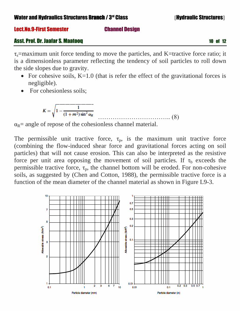
The permissible unit tractive force, τp, is the maximum unit tractive force
(combining the flow-induced shear force and gravitational forces acting on soil
particles) that will not cause erosion. This can also be interpreted as the resistive
force per unit area opposing the movement of soil particles. If τb exceeds the
permissible tractive force, τp, the channel bottom will be eroded. For non-cohesive
soils, as suggested by (Chen and Cotton, 1988), the permissible tractive force is a
function of the mean diameter of the channel material as shown in Figure L9-3.

Water and Hydraulics Structures Branch / 3rd Class [Hydraulic Structures]
Lect.No.9-First Semester Channel Design
Asst. Prof. Dr. Jaafar S. Maatooq 11 of 12
In the tractive force method, a channel cross-section is dimensioned so that neither
the channel bottom nor the sides will be eroded under the design conditions. For
cohesive soils the channel bottom is usually critical, whereas for non-cohesive soils
the sides usually govern the design.
Note: The values of the permissible unit tractive force obtained are for straight
channels. For sinuous channels, these values should be multiplied by a reduction
factor, Cp, taken from Table (L9-3).
Table (L9-3): Reduction factors for sinuous channels
** Channels in cohesive soils will be designed using:-
or
Therefore, the limiting flow depth becomes;
…………………………….. (9)
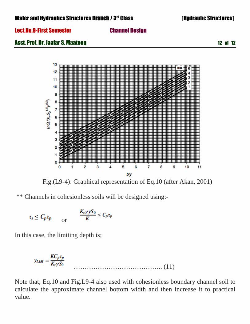
Determine the channel bottom width, b, by using Eq.(10) below or Figure (L9-4);
………………………. (10)
Water and Hydraulics Structures Branch / 3rd Class [Hydraulic Structures]
Lect.No.9-First Semester Channel Design
Asst. Prof. Dr. Jaafar S. Maatooq 12 of 12
Fig.(L9-4): Graphical representation of Eq.10 (after Akan, 2001)
** Channels in cohesionless soils will be designed using:-
or
In this case, the limiting depth is;
………………………………….. (11)
Note that; Eq.10 and Fig.L9-4 also used with cohesionless boundary channel soil to
calculate the approximate channel bottom width and then increase it to practical
value.