lecture 1: an overview of simulation and energyplus material prepared by gard analytics, inc. and...
TRANSCRIPT

Lecture 1: An Overview of Simulation and EnergyPlus
Material prepared by GARD Analytics, Inc. and University of Illinoisat Urbana-Champaign under contract to the National Renewable Energy
Laboratory. All material Copyright 2002-2003 U.S.D.O.E. - All rights reserved

2
Purpose of this Lecture
Gain an understanding of Simulation as a Concept EnergyPlus as a Simulation Tool
Briefly review topics important to your understanding of building thermal simulations
3
What is Simulation?
Definition: “the imitative representation of the functioning of one system or process by means of the functioning of another <a computer simulation of an industrial process>” (Merriam-Webster Dictionary On-Line)
4
What is Building Thermal Simulation?
Approximate definition: a computer model of the energy processes within a building that are intended to provide a thermally comfortable environment for the occupants (or contents) of a building
Examples of building thermal simulation programs: EnergyPlus, Energy-10, BLAST, DOE-2, esp-R, TRNSYS, etc.
5
Goals of Building Thermal Simulation
Load Calculations Generally used for determining sizing
of equipment such as fans, chillers, boilers, etc.
Energy Analysis Helps evaluate the energy cost of the
building over longer periods of time
6
Why is Simulation Important?
Buildings consume roughly one-third of all the energy consumed nationally every year Much of this energy is consumed
maintaining the thermal conditions inside the building and lighting
Simulation can and has played a significant role in reducing the energy consumption of buildings

7
How does Simulation save Energy?
Building thermal simulation allows one to model a building before it is built or before renovations are started
Simulation allows various energy alternatives to be investigated and options compared to one another
Simulation can lead to an energy-optimized building or inform the design process
Simulation is much less expensive and less time consuming than experimentation (every building is different)

8
Quick Review of Important Background Concepts
Control Volumes and the Conservation of: Mass Energy (First Law of Thermodynamics)
Heat Transfer Mechanisms: Conduction—transfer of thermal energy
through a solid Convection—exchange of thermal energy
between a solid and a fluid that are in contact Radiation—exchange of thermal energy via
electro-magnetic waves between bodies or surfaces

9
What is EnergyPlus?
Fully integrated building & HVAC simulation program
Based on best features of BLAST and DOE-2 plus new capabilities
Windows 95/98/NT/2000/XP & LinuxSimulation engine onlyInterfaces available from private
software developers

10
EnergyPlus Concepts
Time dependent conduction Conduction through building surfaces
calculated with conduction transfer functions Heat storage and time lags
Migration between zones Approximates air exchange using a nodal
model
Only models what is explicitly described Missing wall does not let air in Missing roof does not let sun in

11
EnergyPlus Concepts (cont’d)
Heat balance loads calculation (one of two load calculation methods recommended by ASHRAE)
Moisture balance calculationSimultaneous building/systems solutionSub-hourly time stepsModular HVAC system simulationWINDOW 5 methodology
12
EnergyPlus Concepts (cont’d)
Simple input/output file structuresNo surface, zone or system limits
Defaults to 50 coils per HVAC loop Can be increased
Links to other software COMIS, wind-induced airflow TRNYSYS, Photovoltaics

13
EnergyPlus Structure
14
Integrated Simulation Manager
Fully integrated simulation of loads, systems and plant Integrated simulation allows capacity
limits to be modeled more realistically Provides tighter coupling between the
air- and water-side of the system and plant
15
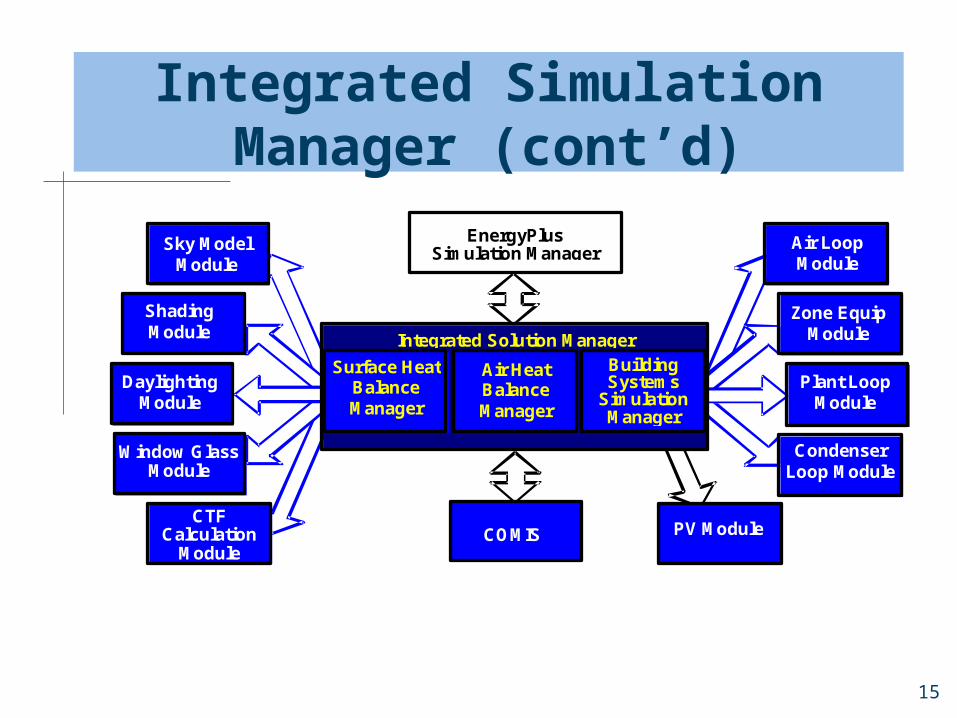
Integrated Simulation Manager (cont’d)
CTF Calculation
Module
Window Glass Module
Daylighting Module
Shading Module
Sky Model Module
COMIS
Building Systems
Simulation Manager
EnergyPlus Simulation Manager
Integrated Solution Manager
Surface Heat Balance Manager
Air Heat Balance Manager
Air Loop Module
Zone Equip Module
Plant Loop Module
Condenser Loop Module
PV Module

16
Input/Output Data
EnergyPlus input and output data files designed for easy maintenance and expansion
Will accept simulation input data from other sources such as CADD programs (AutoCAD, ArchiCAD, Visio), and preprocessors similar to those written for BLAST and DOE 2
An EnergyPlus input file is not intended to be the main interface for typical end-users

17
Input/Output Data (cont’d)
Most users will use EnergyPlus through an interface from a third-party developer
Utilities convert portions of BLAST and DOE 2 input to EnergyPlus input Materials and constructions Schedules Building envelope surfaces

18
Summary
EnergyPlus builds on the strengths of BLAST and DOE-2 and includes many new simulation capabilities: Integrated loads, system and plant
calculations in same time step. User-configurable HVAC system description. Modular structure to facilitate the addition
of new simulation modules. Simple input and output data formats to
facilitate graphical front-end development.

19
Basic Input and Output Issues
General PhilosophyInput/Output Files
Overall File StructuresInput Object Structure
Input Data Dictionary (IDD)Weather Files

20
General Philosophy of Input/Output/Weather
Simple, free-format text filesSI units onlyComma-separatedObject-basedSomewhat self-documentingTwo parts—dictionary and data or
simulation resultsNot user-friendly » Interfaces will helpCan become large
21
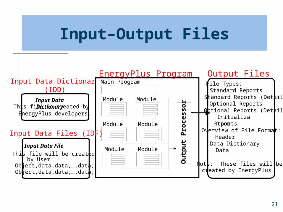
Input–Output Files
Input Data Dictionary
This file is created by
EnergyPlus developers.
Input Data File
This file will be created
by User
Object,data,data,…,data;
Object,data,data,…,data;
Input Data Dictionary(IDD)
EnergyPlus Program Main Program
Module
Module
Module
Module
Module
Module
File Types: Standard Reports Standard Reports (Detail) Optional Reports Optional Reports (Detail) Initialization
Reports Overview of File Format:
Header Data Dictionary Data Note: These files will be
created by EnergyPlus.
Output Files
Ou
tpu
t P
roce
ssor
Input Data Files (IDF)
22
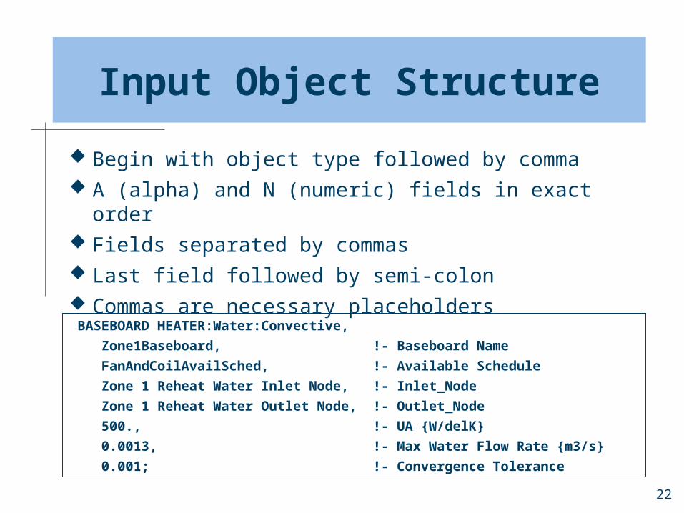
Input Object Structure
Begin with object type followed by comma A (alpha) and N (numeric) fields in exact order Fields separated by commas Last field followed by semi-colon Commas are necessary placeholders BASEBOARD HEATER:Water:Convective,
Zone1Baseboard, !- Baseboard Name
FanAndCoilAvailSched, !- Available Schedule
Zone 1 Reheat Water Inlet Node, !- Inlet_Node
Zone 1 Reheat Water Outlet Node, !- Outlet_Node
500., !- UA {W/delK}
0.0013, !- Max Water Flow Rate {m3/s}
0.001; !- Convergence Tolerance
23
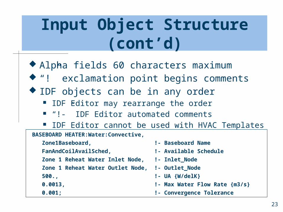
Input Object Structure (cont’d)
Alpha fields 60 characters maximum “!” exclamation point begins comments IDF objects can be in any order
IDF Editor may rearrange the order “!-” IDF Editor automated comments IDF Editor cannot be used with HVAC Templates
BASEBOARD HEATER:Water:Convective,
Zone1Baseboard, !- Baseboard Name
FanAndCoilAvailSched, !- Available Schedule
Zone 1 Reheat Water Inlet Node, !- Inlet_Node
Zone 1 Reheat Water Outlet Node, !- Outlet_Node
500., !- UA {W/delK}
0.0013, !- Max Water Flow Rate {m3/s}
0.001; !- Convergence Tolerance

24
Input Object Structure (cont’d)
Not case-sensitive Input processor checks basic rules, A vs. N,
number of fields, valid object type, max/min, etc.
IDF objects are generally retrieved by each component simulation module BASEBOARD HEATER:Water:Convective,
Zone1Baseboard, !- Baseboard Name
FanAndCoilAvailSched, !- Available Schedule
Zone 1 Reheat Water Inlet Node, !- Inlet_Node
Zone 1 Reheat Water Outlet Node, !- Outlet_Node
500., !- UA {W/delK}
0.0013, !- Max Water Flow Rate {m3/s}
0.001; !- Convergence Tolerance

25
Input Data Dictionary (IDD File)
Energy+.iddLocated in
EnergyPlus folderConceptually
simple A (alpha) or N (Numeric)
BASEBOARD HEATER:Water:Convective,
A1 , \field Baseboard Name
\required-field
A2 , \field Available Schedule
\required-field
\type object-list
\object-list ScheduleNames
. . .
N1 , \field UA
\required-field
\autosizable
\units W/delK
. . .
N3 ; \field Convergence Tolerance
\type real
\Minimum> 0.0
\Default 0.001
26
IDD File (cont’d)
Lists every available input object If it isn’t in the IDD, then it’s not
available IDD version must be consistent with
exe version IDD is the final word (even if other
documentation does not agree)
27
IDD File (cont’d)
“\”code Specifications Field descriptions Units Value ranges (minimum, maximum) Defaults Autosizing
28
IDD File (cont’d)
Get to know the IDD fileEasy way to quickly check object
syntaxRefer to Input Output Reference for
detailed explanations of inputs

29
Allowable Ranges and Defaults
Allowable ranges Some max/min declared in IDD
Fatal error if outside of range Some max/min hidden in source code
May reset value and issue warning, may be fatal
Defaults Some defaults declared in IDD Some defaults hidden in source code Some values have no defaults
Alphas become blank Numerics become zero

30
Weather Data(epw file)
Weather year for energy use comparisons, similar to other programs
Hourly, can be subhourlyHourly data is linearly interpolatedData include temperature,
humidity, solar, wind, etc.Several included in standard install

31
Output Data Format
Same philosophy as for input; somewhat human readable output files
EnergyPlus can perform some output processing to help limit output size
User definable variable level reporting

32
Output Reporting Flexibility
User can select any variables available for output
User can specify output at time step, hourly, daily, monthly, or environment intervals
User can schedule each output variable
User can select various meters by resource and end-use

33
Questions
How long will my simulation take? Depends on size of input file, length of
simulation period (day vs. year), and speed of computer
Might range from a few seconds to several minutes (some detailed simulation modules may require even longer)
EnergyPlus will display progress in a window on the desktop so that the user knows where it is at

34
Questions (cont’d)
How do I know whether the program read my input correctly?
Take a look at the .EIO file (EnergyPlus initialization output)—this may indicate that you have misinterpreted an input parameter
Check results output files and see if they are reasonable How will I know whether my simulation results
are reasonable or outrageous? See previous question Consider “Load Check Figures” available from sources
such as ASHRAE Compare to other simulations or consult your instructor Do some simple hand calculations (such as UAT) and
see if the numbers are “in the ballpark”