lecture 23: primary system loops and components material prepared by gard analytics, inc. and...
TRANSCRIPT
Lecture 23: Primary System Loops and Components
Material prepared by GARD Analytics, Inc. and University of Illinoisat Urbana-Champaign under contract to the National Renewable Energy
Laboratory. All material Copyright 2002-2003 U.S.D.O.E. - All rights reserved
2
Purpose of this Lecture
Gain an understanding of: EnergyPlus loop controls Some of the many EnergyPlus plant
and condenser components

3
Keywords Categories Covered in this Lecture
Plant Loop and Condenser LoopPlant Operation Schemes,
Cooling/Heating Load Range Based Operation, Load Range Equipment List
CoilPumpBoilerChillerCooling TowerCurve
4
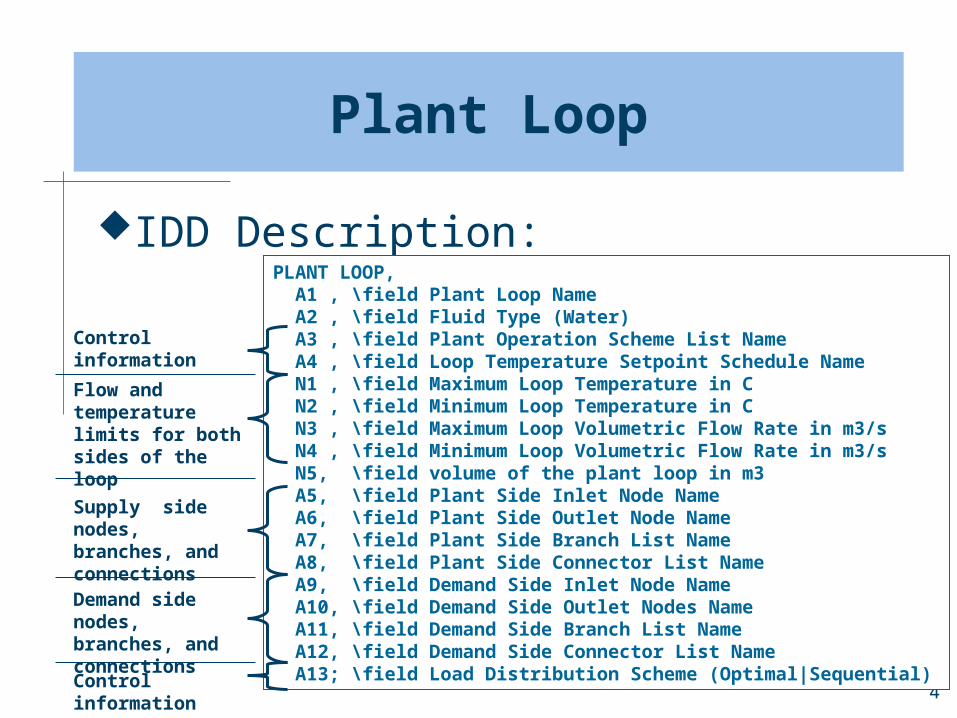
Plant Loop
IDD Description:PLANT LOOP, A1 , \field Plant Loop Name A2 , \field Fluid Type (Water) A3 , \field Plant Operation Scheme List Name A4 , \field Loop Temperature Setpoint Schedule Name N1 , \field Maximum Loop Temperature in C N2 , \field Minimum Loop Temperature in C N3 , \field Maximum Loop Volumetric Flow Rate in m3/s N4 , \field Minimum Loop Volumetric Flow Rate in m3/s N5, \field volume of the plant loop in m3 A5, \field Plant Side Inlet Node Name A6, \field Plant Side Outlet Node Name A7, \field Plant Side Branch List Name A8, \field Plant Side Connector List Name A9, \field Demand Side Inlet Node Name A10, \field Demand Side Outlet Nodes Name A11, \field Demand Side Branch List Name A12, \field Demand Side Connector List Name A13; \field Load Distribution Scheme (Optimal|Sequential)
Control information
Flow and temperature limits for both sides of the loop
Supply side nodes, branches, and connectionsDemand side nodes, branches, and connectionsControl information
5
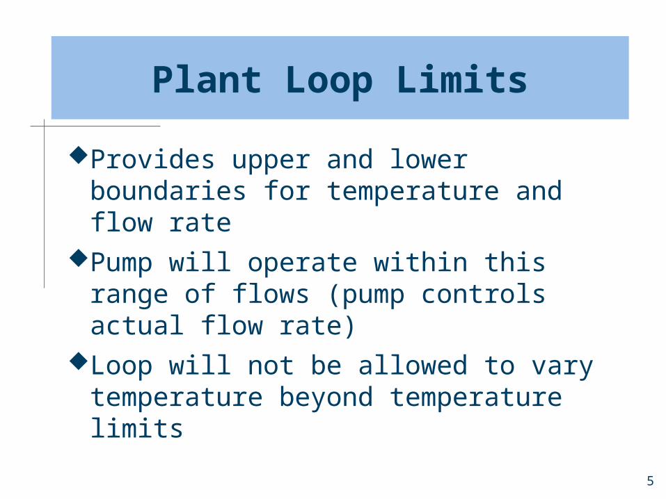
Plant Loop Limits
Provides upper and lower boundaries for temperature and flow rate
Pump will operate within this range of flows (pump controls actual flow rate)
Loop will not be allowed to vary temperature beyond temperature limits

6
Plant Loop Controls: Temperature
Setpoint temperature for plant loop can be scheduled
Plant loop will run equipment as needed and as defined by the remaining controls to meet setpoint temperature
If not enough equipment capacity, loop setpoint temperature may not be met (can “catch-up” in future time steps)
Pump controls will determine loop flow rate

7
Plant Loop Controls: Load Distribution
Sequential Sequential simply operates equipment in a serial
manner based on the loop operation scheme (which assigns priority to different equipment on the loop)
When highest priority equipment is out of capacity, next highest priority equipment tries to meet the load, etc.
Optimal Parallel operation of equipment Tries to find an “optimal” balance of the plant loop
load between equipment based on the operating characteristics of the equipment on the loop
Not a strict optimization, simply an approximation at what might be the best load distribution from an energy perspective

8
Plant Loop Controls: Operation Scheme
List of load ranges that define which equipment might try to meet a load
Requires following input: Plant Operation Schemes—a list of load range
definitions and the schedules for when they are in effect
Cooling/Heating Load Range Based Operation—a list of load ranges and the lists of equipment that are operating for those ranges
Load Range Equipment List—the equipment lists referenced by the load ranges

9
Plant Loop Controls: Operation Scheme Example
PLANT OPERATION SCHEMES, CW Loop Operation, !- Plant Operation Scheme Name LOAD RANGE BASED OPERATION, !- KEY--Control Scheme 1 Peak Operation, !- Control Scheme Name 1 On Peak, !- Control Scheme Schedule 1 LOAD RANGE BASED OPERATION, !- KEY--Control Scheme 2 Off Peak Operation, !- Control Scheme Name 2 Off Peak; !- Control Scheme Schedule 2
COOLING LOAD RANGE BASED OPERATION, Peak Operation, !- Name 0, !- Load Range Lower Limit 1 {W} 70000, !- Load Range Upper Limit 1 {W} Chiller Plant, !- Priority Control Equip List Name 1 70000, !- Load Range Lower Limit 2 {W} 245000, !- Load Range Upper Limit 2 {W} Chiller Plant and Purchased, !- Priority Control Equip List Name 2 245000, !- Load Range Lower Limit 3 {W} 500000, !- Load Range Upper Limit 3 {W} Purchased Only; !- Priority Control Equip List Name 3
COOLING LOAD RANGE BASED OPERATION, Off Peak Operation, !- Name 0, !- Load Range Lower Limit 1 {W} 900000, !- Load Range Upper Limit 1 {W} All Chillers; !- Priority Control Equip List Name 1
Referenced in Plant Loop input
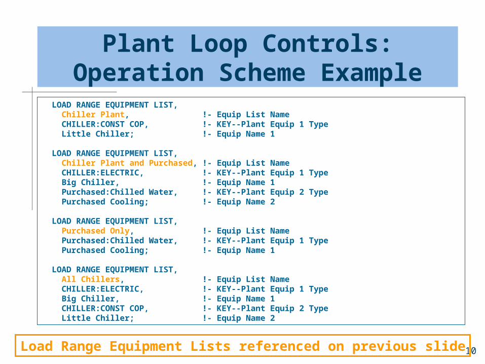
10
Plant Loop Controls: Operation Scheme Example
LOAD RANGE EQUIPMENT LIST, Chiller Plant, !- Equip List Name CHILLER:CONST COP, !- KEY--Plant Equip 1 Type Little Chiller; !- Equip Name 1
LOAD RANGE EQUIPMENT LIST, Chiller Plant and Purchased, !- Equip List Name CHILLER:ELECTRIC, !- KEY--Plant Equip 1 Type Big Chiller, !- Equip Name 1 Purchased:Chilled Water, !- KEY--Plant Equip 2 Type Purchased Cooling; !- Equip Name 2
LOAD RANGE EQUIPMENT LIST, Purchased Only, !- Equip List Name Purchased:Chilled Water, !- KEY--Plant Equip 1 Type Purchased Cooling; !- Equip Name 1
LOAD RANGE EQUIPMENT LIST, All Chillers, !- Equip List Name CHILLER:ELECTRIC, !- KEY--Plant Equip 1 Type Big Chiller, !- Equip Name 1 CHILLER:CONST COP, !- KEY--Plant Equip 2 Type Little Chiller; !- Equip Name 2
Load Range Equipment Lists referenced on previous slide

11
Example: Plant Loop
PLANT LOOP, Chilled Water Loop, !- Plant Loop Name Water, !- Fluid Type CW Loop Operation, !- Plant Operation Scheme List Name CW Loop Temp Schedule, !- Loop Temperature Setpoint Schedule Name 98, !- Maximum Loop Temperature {C} 1, !- Minimum Loop Temperature {C} 0.0011, !- Maximum Loop Volumetric Flow Rate {m3/s} 0, !- Minimum Loop Volumetric Flow Rate {m3/s} autosize, !- volume of the plant loop {m3} CW Supply Inlet Node, !- Plant Side Inlet Node Name CW Supply Outlet Node, !- Plant Side Outlet Node Name Cooling Supply Side Branches, !- Plant Side Branch List Name Cooling Supply Side Connectors, !- Plant Side Connector List Name CW Demand Inlet Node, !- Demand Side Inlet Node Name CW Demand Outlet Node, !- Demand Side Outlet Nodes Name Cooling Demand Side Branches, !- Demand Side Branch List Name Cooling Demand Side Connectors, !- Demand Side Connector List Name Optimal; !- Load Distribution Scheme
12
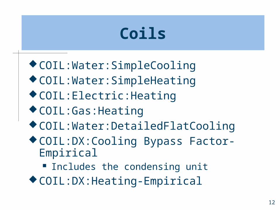
Coils
COIL:Water:SimpleCoolingCOIL:Water:SimpleHeatingCOIL:Electric:HeatingCOIL:Gas:HeatingCOIL:Water:DetailedFlatCoolingCOIL:DX:Cooling Bypass Factor-
Empirical Includes the condensing unit
COIL:DX:Heating-Empirical
13
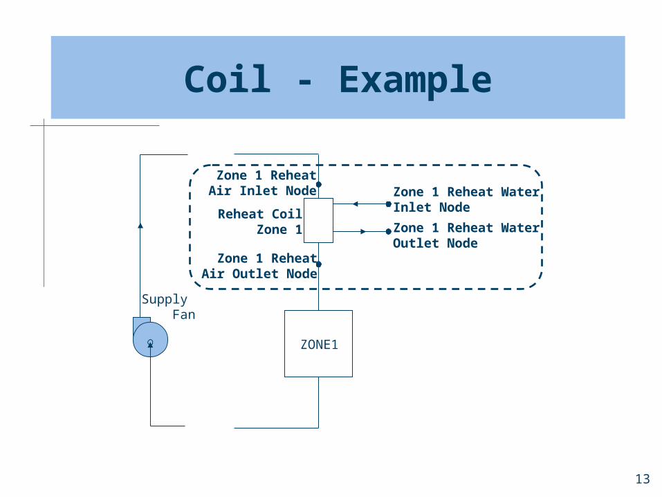
Coil - Example
Supply Fan
ZONE1
Reheat CoilZone 1
Zone 1 ReheatAir Outlet Node
Zone 1 ReheatAir Inlet Node Zone 1 Reheat Water
Inlet Node
Zone 1 Reheat WaterOutlet Node
14
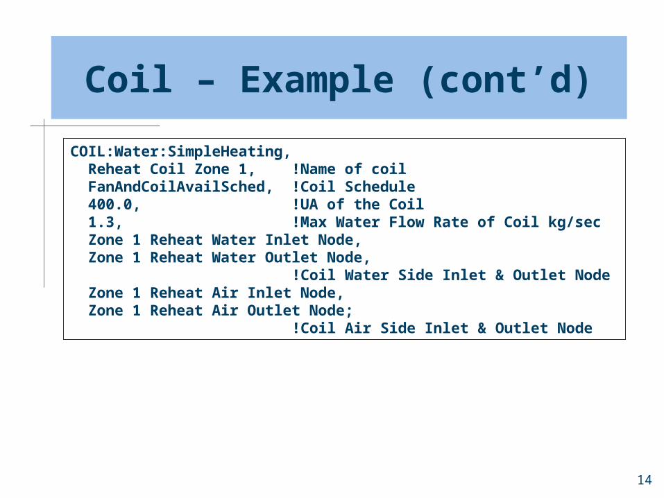
Coil – Example (cont’d)
COIL:Water:SimpleHeating, Reheat Coil Zone 1, !Name of coil FanAndCoilAvailSched, !Coil Schedule 400.0, !UA of the Coil 1.3, !Max Water Flow Rate of Coil kg/sec Zone 1 Reheat Water Inlet Node, Zone 1 Reheat Water Outlet Node, !Coil Water Side Inlet & Outlet Node Zone 1 Reheat Air Inlet Node, Zone 1 Reheat Air Outlet Node; !Coil Air Side Inlet & Outlet Node

15
Pump – Example
CW Supply Inlet Node
CW Pump Outlet Node
Circ Pump
Chiller 1 Chiller 2
Cond. Demand Side Loop
Plant Supply SideCooling Loop
Plant Demand SideCooling Loop

16
Pump – Example (cont’d)
PUMP:CONSTANT SPEEDPUMP:VARIABLE SPEED PUMP:VARIABLE SPEED, CW Circ Pump, !- Pump Name CW Supply Inlet Node, !- Inlet_Node CW Pump Outlet Node, !- Outlet_Node .0013, !- Rated Volumetric Flow Rate {m3/s} 300000, !- Rated Pump Head {Pa} 560, !- Rated Power Consumption {W} .87, !- Motor Efficiency 0.0, !- Fraction of Motor Inefficiencies to Fluid Stream 0, !- Coefficient1 of the Part Load Performance Curve 1, !- Coefficient2 of the Part Load Performance Curve 0, !- Coefficient3 of the Part Load Performance Curve 0, !- Coefficient4 of the Part Load Performance Curve 0, !- Min Flow Rate in variable flow capacity;{m3/s} INTERMITTENT; !- Pump Control Type
17
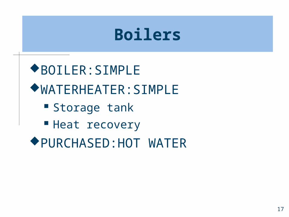
Boilers
BOILER:SIMPLEWATERHEATER:SIMPLE
Storage tank Heat recovery
PURCHASED:HOT WATER

18
Boiler - Example
Boiler
BoilerInlet Node
BoilerOutlet Node
Plant Supply SideHeating Loop
Plant Demand SideHeating Loop
±HW Pump
Heating Coil

19
Boiler – Example (cont’d)
BOILER:SIMPLE, Boiler Plant Boiler,! Boiler Name GAS, ! Fuel Type 25000, ! Nominal Capacity {W} 0.8, ! Theoretical Boiler Efficiency 100, ! Design Boiler Water Outlet Temp {C} 0.0021, ! Max Design Boiler Water Flow Rate {m3/s} 0.10, ! Minimum Part Load Ratio 1.00, ! Maximum Part Load Ratio 1.00, ! Opt Part Load Ratio 1.0, ! Coefficient1 of the fuel use/part load ratio curve 0.0, ! Coefficient2 of the fuel use/part load ratio curve 0.0, ! Coefficient3 of the fuel use/part load ratio curve Boiler Inlet Node, ! Boiler_Water_Inlet_Node Boiler Outlet Node, ! Boiler_Water_Outlet_Node 100, ! Temp Upper Limit Water Outlet {C} ConstantFlow; ! Boiler Flow Mode (v1.0.1)
20
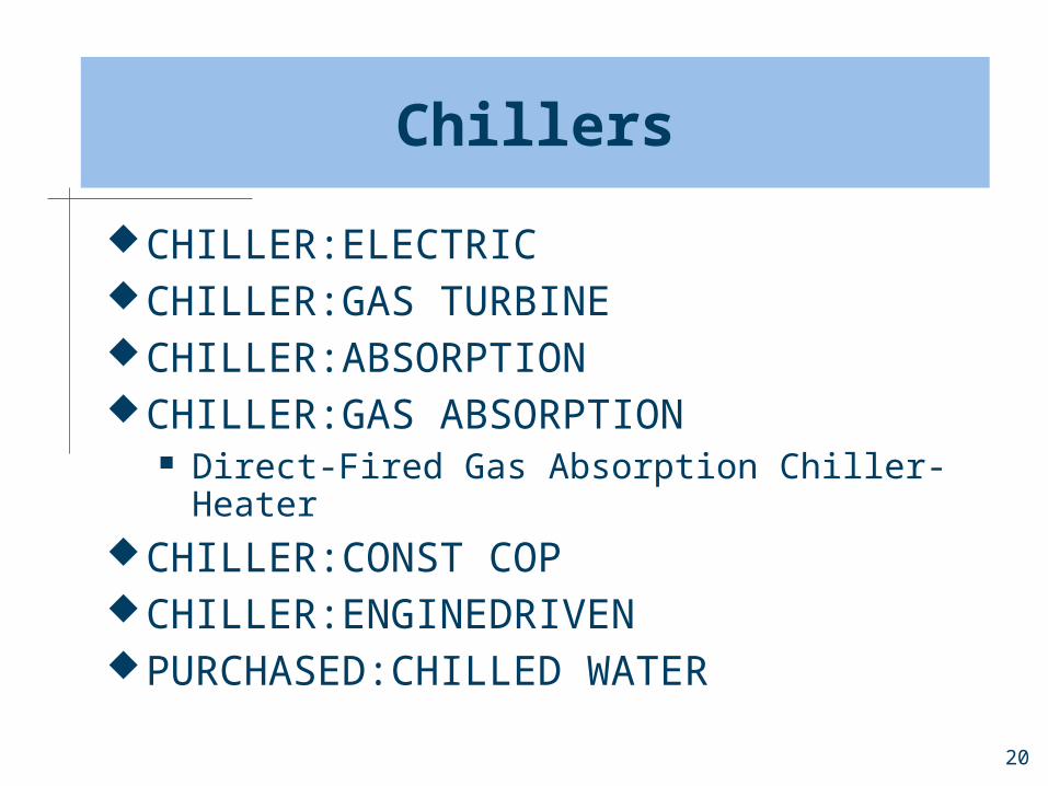
Chillers
CHILLER:ELECTRICCHILLER:GAS TURBINECHILLER:ABSORPTIONCHILLER:GAS ABSORPTION
Direct-Fired Gas Absorption Chiller-HeaterCHILLER:CONST COPCHILLER:ENGINEDRIVENPURCHASED:CHILLED WATER
21
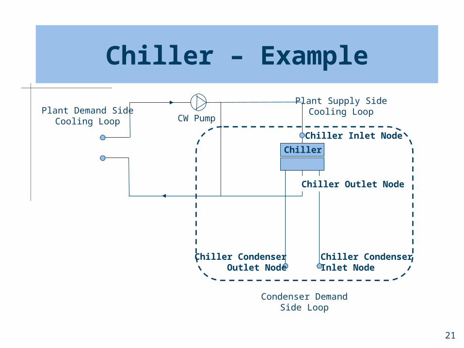
Chiller – Example
Chiller
Chiller Inlet Node
Chiller Outlet Node
Chiller CondenserInlet Node
Chiller CondenserOutlet Node
Condenser DemandSide Loop
Plant Supply SideCooling Loop
CW PumpPlant Demand Side
Cooling Loop

22
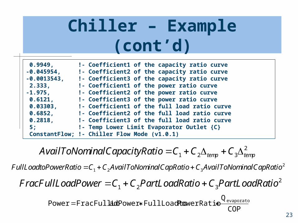
Chiller – Example (cont’d)
CHILLER:ELECTRIC, Big Chiller, !- Chiller Name WATER COOLED, !- Condenser Type 100000, !- Nominal Capacity {W} 2.75, !- COP Big Chiller Inlet Node, !- Plant_Side_Inlet_Node Big Chiller Outlet Node, !- Plant_Side_Outlet_Node Big Chiller Condenser Inlet Node, !- Condenser_Side_Inlet_Node Big Chiller Condenser Outlet Node, !- Condenser_Side_Outlet_Node .15, !- Minimum Part Load Ratio 1.0, !- Maximum Part Load Ratio .65, !- Opt Part Load Ratio 35.0, !- Temp Design Condenser Inlet {C} 2.778, !- Temp Rise Coefficient 6.67, !- Temp Design Evaporator Outlet {C} 0.0011, !- Design Evaporator Vol Water Flow Rate {m3/s} (v1.0.1) 0.0011, !- Design Condenser Volumetric Water Flow Rate
23
Chiller – Example (cont’d)
21 2 3temp tempAvailToNominalCapacityRatio C C C
21 2 3FullLoadtoPowerRatio C C AvailToNominalCapRatio C AvailToNominalCapRatio
21 2 3FracFullLoadPower C C PartLoadRatio C PartLoadRatio
0.9949, !- Coefficient1 of the capacity ratio curve-0.045954, !- Coefficient2 of the capacity ratio curve-0.0013543, !- Coefficient3 of the capacity ratio curve 2.333, !- Coefficient1 of the power ratio curve-1.975, !- Coefficient2 of the power ratio curve 0.6121, !- Coefficient3 of the power ratio curve 0.03303, !- Coefficient1 of the full load ratio curve 0.6852, !- Coefficient2 of the full load ratio curve 0.2818, !- Coefficient3 of the full load ratio curve 5; !- Temp Lower Limit Evaporator Outlet {C} ConstantFlow; !- Chiller Flow Mode (v1.0.1)
COP
QPowerRatioFullLoadtoadPowerFracFullLoPower evaporator

24
Cooling Tower – Example
Condenser TowerInlet Node
Condenser TowerOutlet Node
Tower
Cond Demand Side Loop
Plant Supply SideCooling Loop

25
Cooling Tower – Example (cont’d)
COOLING TOWER:TWO SPEEDCOOLING TOWER:SINGLE SPEED
2 Input Methods UA and Design Water Flow Rate
COOLING TOWER:SINGLE SPEED, Big Tower1, !- Tower Name Condenser Tower 1 Inlet Node, !- Water Inlet Node Name Condenser Tower 1 Outlet Node, !- Water Outlet Node Name .0011, !- Design Water Flow Rate {m3/s} 8.0, !- Design Air Flow Rate {m3/s} 500, !- Fan Power at Design Air Flow Rate {W} 175.0, !- Tower UA Value at Design Air Flow Rate {W/K} 0.0, !- Air Flow Rate in Free Convection Regime {m3/s} 0.0, !- Tower UA Value at Free Convection Air Flow Rate {W/K} UA and Design Water Flow Rate; !- Tower Performance Input Method
26
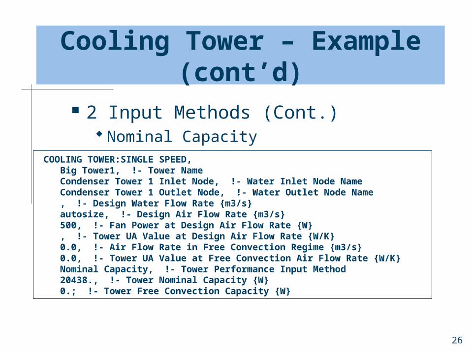
Cooling Tower – Example (cont’d)
2 Input Methods (Cont.) Nominal Capacity
COOLING TOWER:SINGLE SPEED, Big Tower1, !- Tower Name Condenser Tower 1 Inlet Node, !- Water Inlet Node Name Condenser Tower 1 Outlet Node, !- Water Outlet Node Name , !- Design Water Flow Rate {m3/s} autosize, !- Design Air Flow Rate {m3/s} 500, !- Fan Power at Design Air Flow Rate {W} , !- Tower UA Value at Design Air Flow Rate {W/K} 0.0, !- Air Flow Rate in Free Convection Regime {m3/s} 0.0, !- Tower UA Value at Free Convection Air Flow Rate {W/K} Nominal Capacity, !- Tower Performance Input Method 20438., !- Tower Nominal Capacity {W} 0.; !- Tower Free Convection Capacity {W}

27
Curve Objects
CURVE:CUBICCURVE:QUADRATICCURVE:BIQUADRATIC CURVE:BIQUADRATIC, Sample Curve, !- Name 1.000, !- Coeff1 Constant 0.100, !- Coeff2 x 0.001, !- Coeff3 x**2 0.200, !- Coeff4 y 0.002, !- Coeff5 y**2 0.003, !- Coeff6 x*y 0, !- minimum value of x 100, !- maximum value of x 0, !- minimum value of y 100; !- maximum value of y

28
Summary
Each component on the primary system loops has specific input requirements that are unique to that component type
Some components may link between two different loops, for example: Coils—air/zone equipment loop and plant
demand side Chiller—plant supply side and condenser
demand sidePrimary loops have temperature, flow,
and operational controls that must be defined by the program user