lecture 14 – serial peripheral interface …atomicrhubarb.com/files/system/class_slides/14...
TRANSCRIPT
www.atomicrhubarb.com/systemsLecture 14 – Serial Peripheral Interface
Section Topic
● Where in the books● Zilog PS220 "Enhanced Serial Peripheral
Interface" ● Assorted datasheets
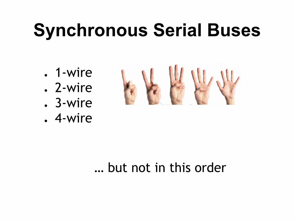
Synchronous Serial Buses
● 1-wire ● 2-wire● 3-wire● 4-wire
… but not in this order
Serial Buses
● Communication between components○ Typically between integrated circuit
components○ CPU to peripherals
● Typically short distances (at least that was the plan) like inches.
● Number of wires = number of SIGNAL wires○ Power & ground not included in the counting
● Usually synchronous (data on one line and clock on another)
● Lots of variety, lots of similarity.

● The nice thing about standards is that there are so many of them to choose from.
- Andrew Tannenbaum
Why so many?
1,2,3,4 wire?
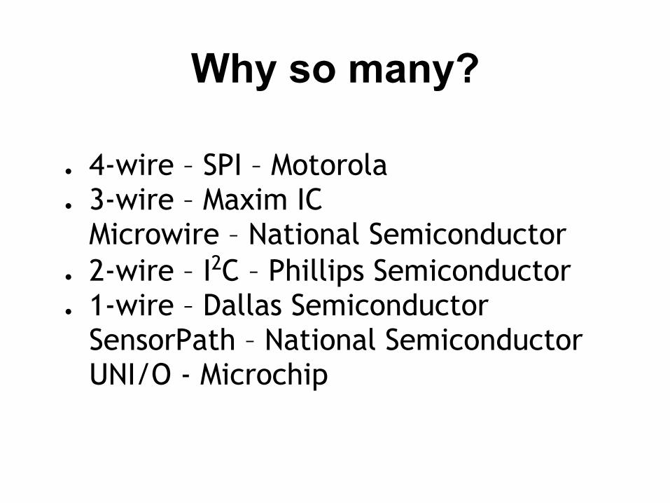
Why so many?
● 4-wire – SPI – Motorola ● 3-wire – Maxim IC
Microwire – National Semiconductor● 2-wire – I2C – Phillips Semiconductor● 1-wire – Dallas Semiconductor
SensorPath – National SemiconductorUNI/O - Microchip
SPI (4 wire)
● Serial Peripheral Interface● 4 wires (really 3 + 1 for each device)● Low Cost● Simple● Intended for CPU to Peripheral
communication and control. ● Defined by Motorola.
SPI Specification
● The Specification is hidden inside the HC08 microcontroller data sheets
● Motorola Semiconductor is now Freescale Semiconductor.
● Defines 4 signals
Master/Slave
● Since SPI is intended for CPU to control peripherals
● The CPU is the master (controller)● Any peripheral is the slave (controlled)
SPI Signals
● SCLK – Serial Clock● MISO – Master In, Slave Out● MOSI – Master Out, Slave In● SS – Slave Select
● Based on shifting data between 2 shift registers.

Whats a shift register?
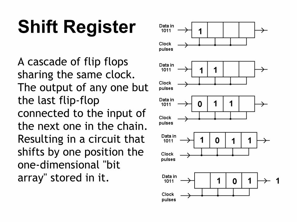
Shift Register
A cascade of flip flops sharing the same clock. The output of any one but the last flip-flop connected to the input of the next one in the chain. Resulting in a circuit that shifts by one position the one-dimensional "bit array" stored in it.
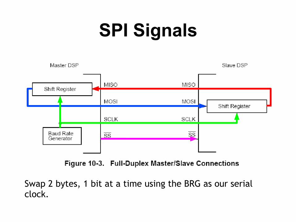
SPI Signals
Swap 2 bytes, 1 bit at a time using the BRG as our serial clock.
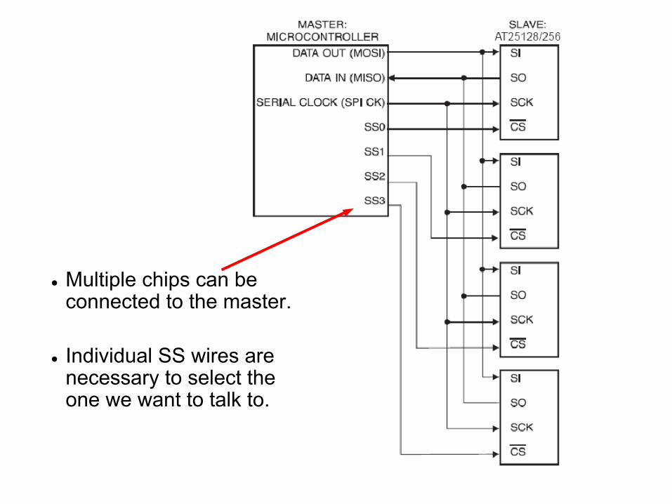
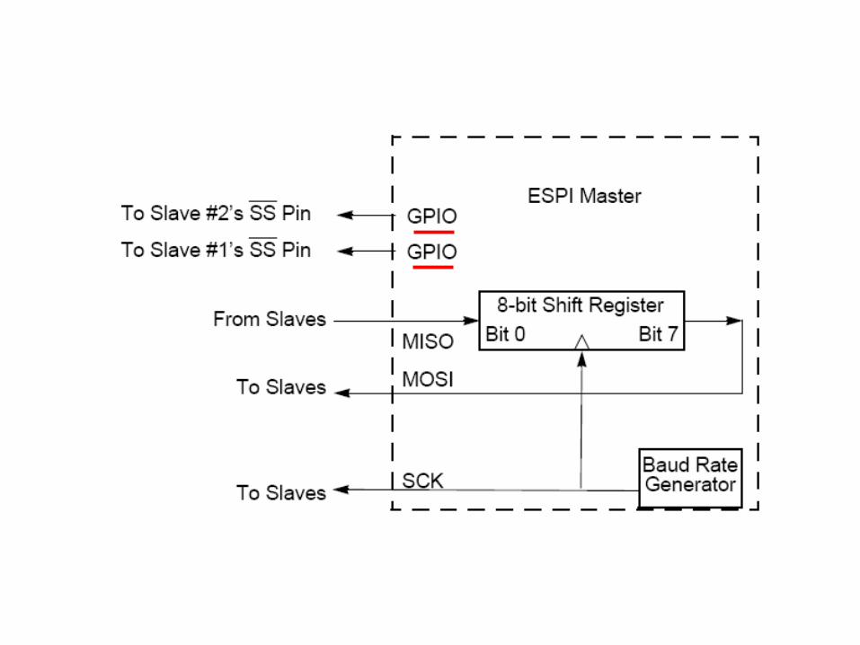
● Multiple chips can beconnected to the master.
● Individual SS wires are necessary to select theone we want to talk to.
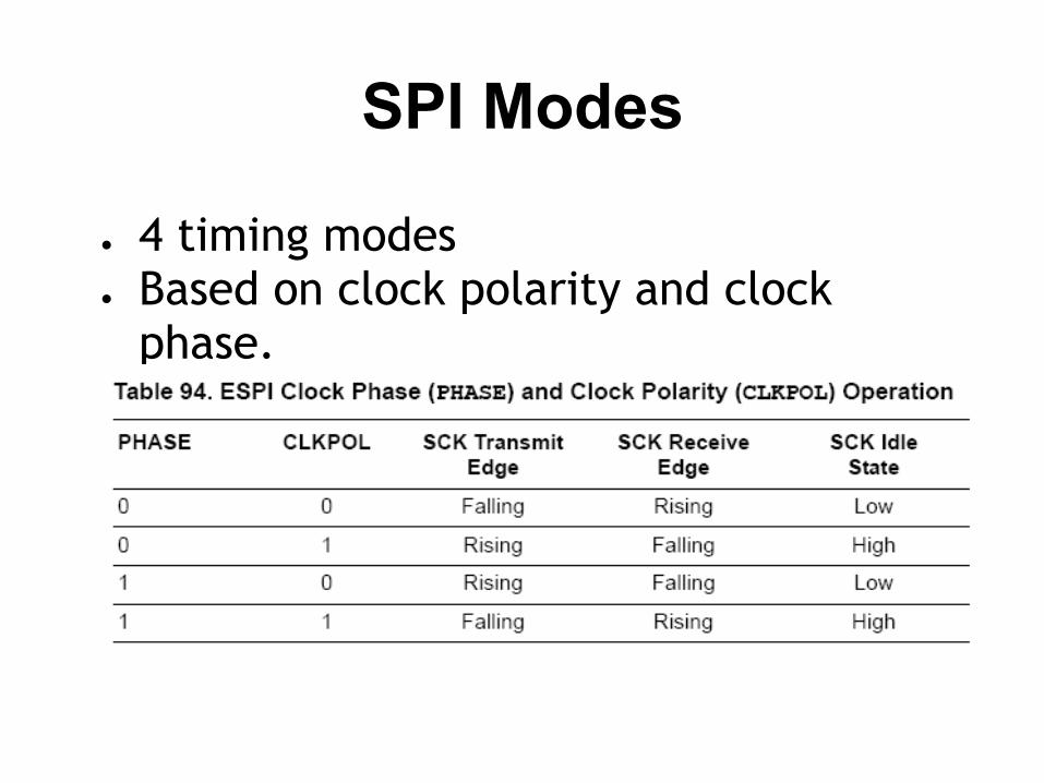
SPI Modes
● 4 timing modes● Based on clock polarity and clock
phase.

Timing
● It is common to see a reference to the SPI mode as CKPOL = 0, PHASE = 0
● This is by far the most common SPI transfer.
SPI data
● While the signalling is SPI, the data:● Is device specific● Some need a single byte● Some need multiple bytes● Reads follow writes● A dummy write is necessary to initiate
a read.

What?
A dummy write is necessary to initiate a read. Why?

To read THIS data we need to write something (anything) to shift the slave data to the master.
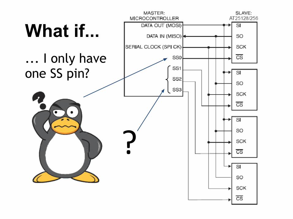
... I only haveone SS pin?
What if...
SPI Devices
● IO Expanders● Clocks● Temperature Sensors● Non-volatile memory● ... lots of things.
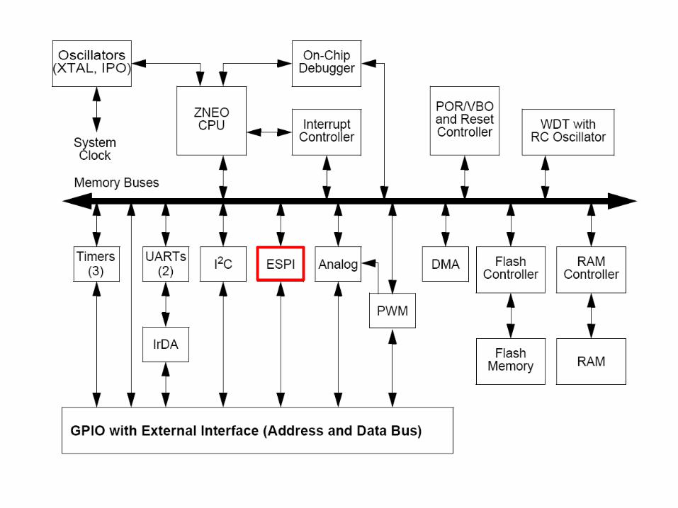
ESPI on the ZNEO
● Enhanced Serial Peripheral Interface
ESPI● The Enhanced Serial Peripheral Interface (SPI) is a synchronous
interface allowing several SPI-type devices to be interconnected. SPI-compatible devices include EEPROMs, Analog-to-Digital Converters, and ISDN devices. Features of the SPI include:
● Full-duplex, synchronous, character-oriented communication● Four-wire interface● Data transfers rates up to a maximum of one-fourth the system
clock frequency● Error detection● Write and mode collision detection● Dedicated Baud Rate Generator
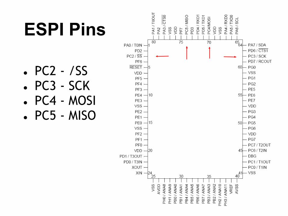
ESPI Pins
● PC2 - /SS● PC3 - SCK● PC4 - MOSI● PC5 - MISO
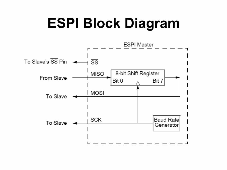
ESPI Block Diagram
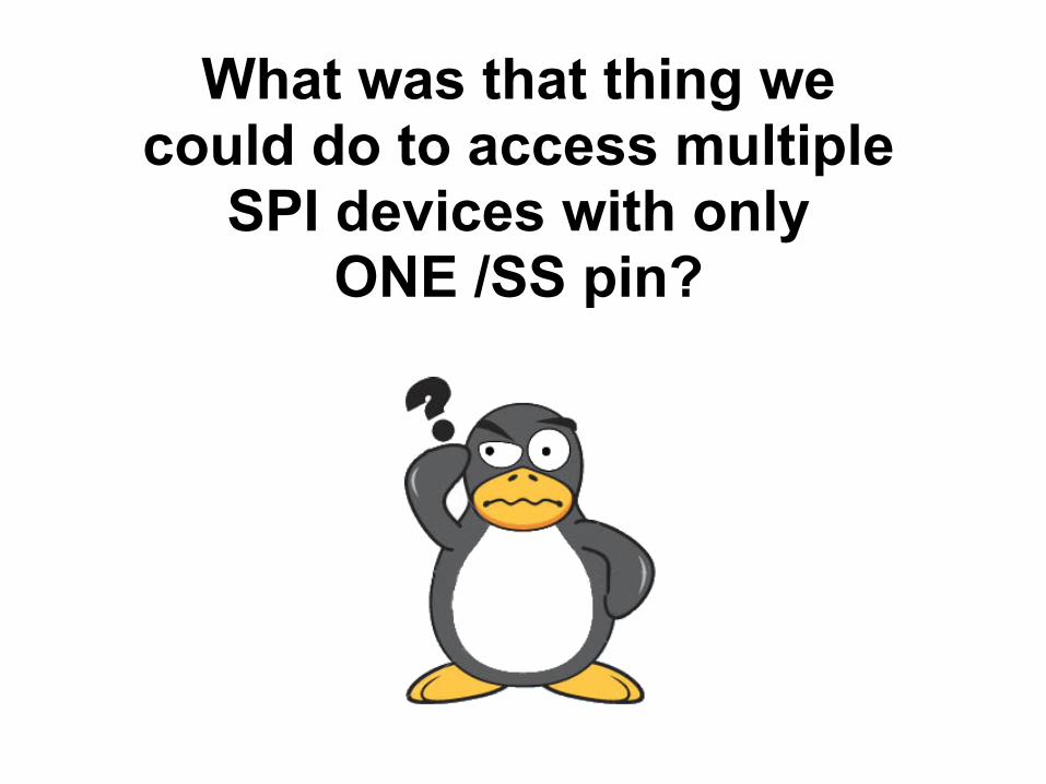
What was that thing we could do to access multiple
SPI devices with onlyONE /SS pin?
ESPI
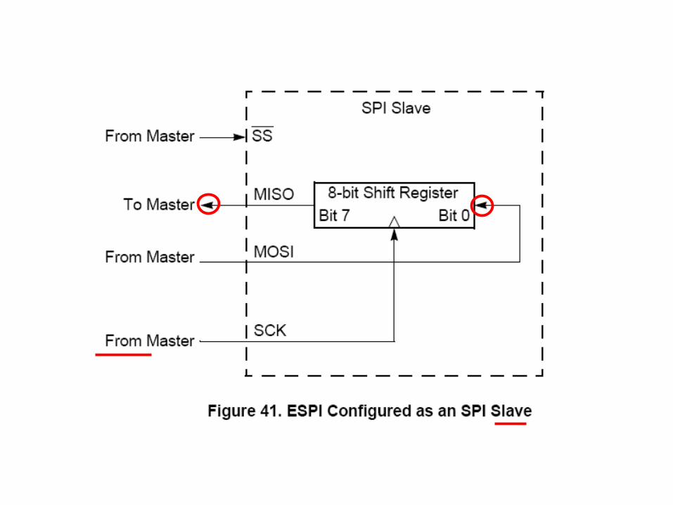
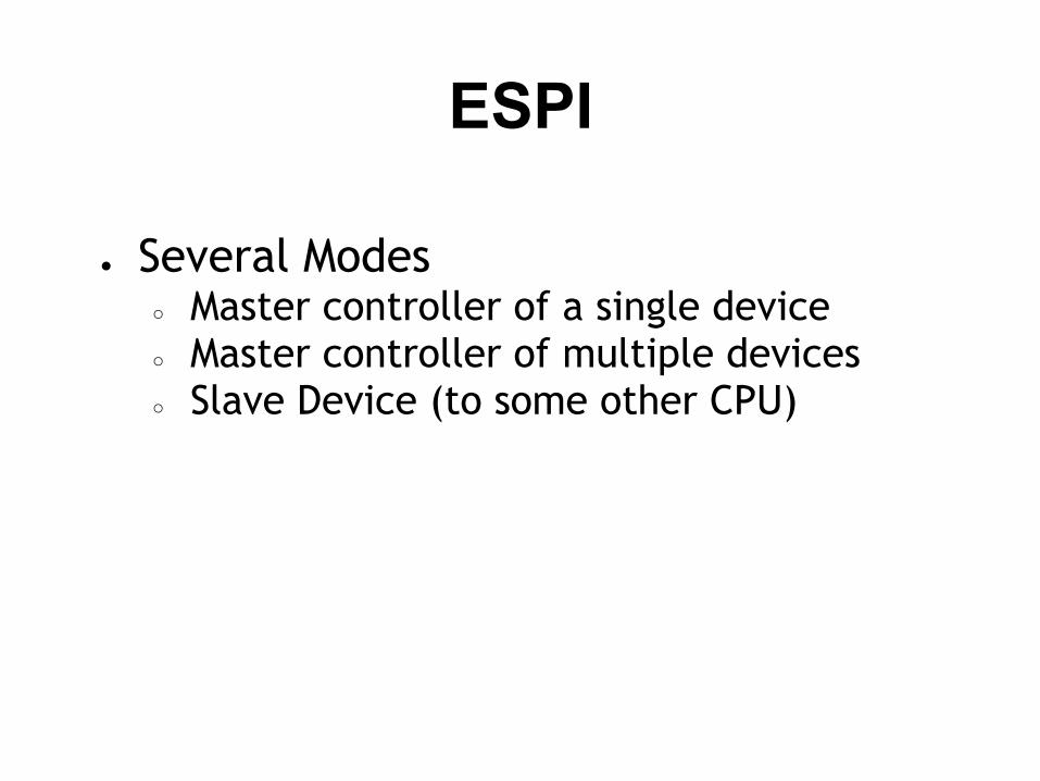
● Several Modes○ Master controller of a single device○ Master controller of multiple devices○ Slave Device (to some other CPU)
Why would you want the ZNEO to be an SPI slave device?
ESPI Registers
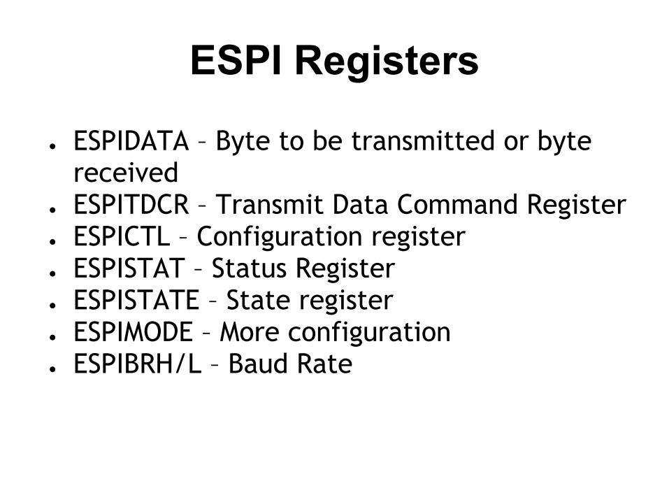
● ESPIDATA – Byte to be transmitted or byte received
● ESPITDCR – Transmit Data Command Register● ESPICTL – Configuration register● ESPISTAT – Status Register● ESPISTATE – State register● ESPIMODE – More configuration● ESPIBRH/L – Baud Rate
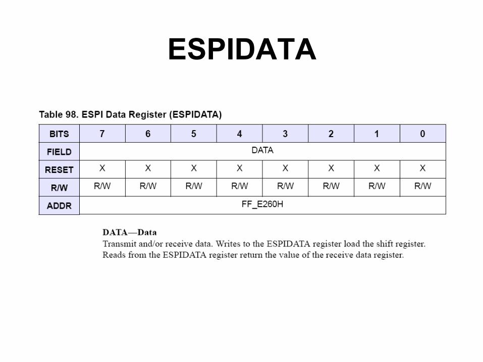
ESPIDATA
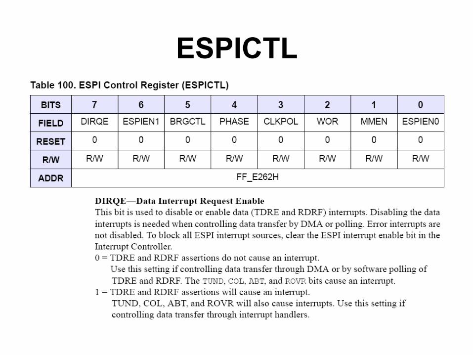
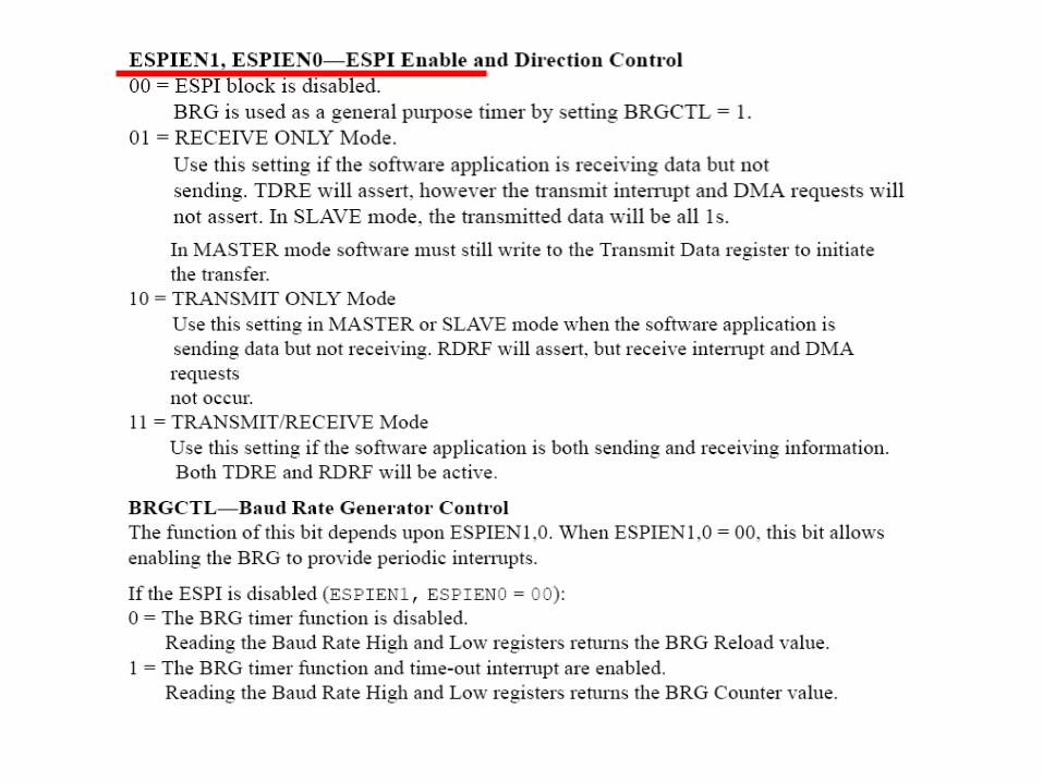
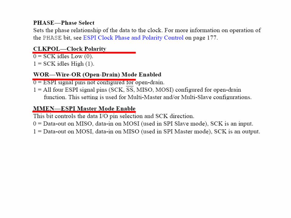
ESPICTL
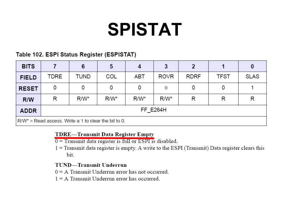
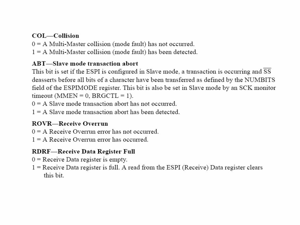
SPISTAT
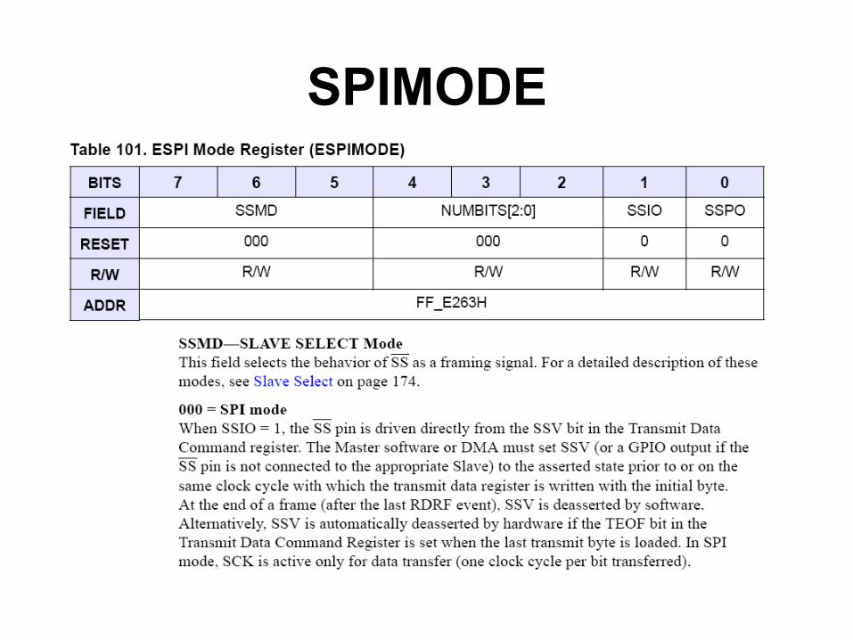
SPIMODE
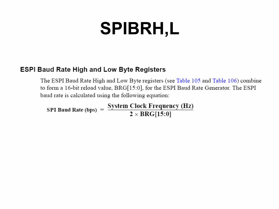
SPIBRH,L
Z16 Recipe
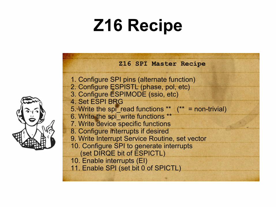
Z16 SPI Master Recipe
1. Configure SPI pins (alternate function)2. Configure ESPISTL (phase, pol, etc)3. Configure ESPIMODE (ssio, etc)4. Set ESPI BRG5. Write the spi_read functions ** (** = non-trivial)6. Write the spi_write functions **7. Write device specific functions8. Configure interrupts if desired9. Write Interrupt Service Routine, set vector10. Configure SPI to generate interrupts (set DIRQE bit of ESPICTL)10. Enable interrupts (EI)11. Enable SPI (set bit 0 of SPICTL)
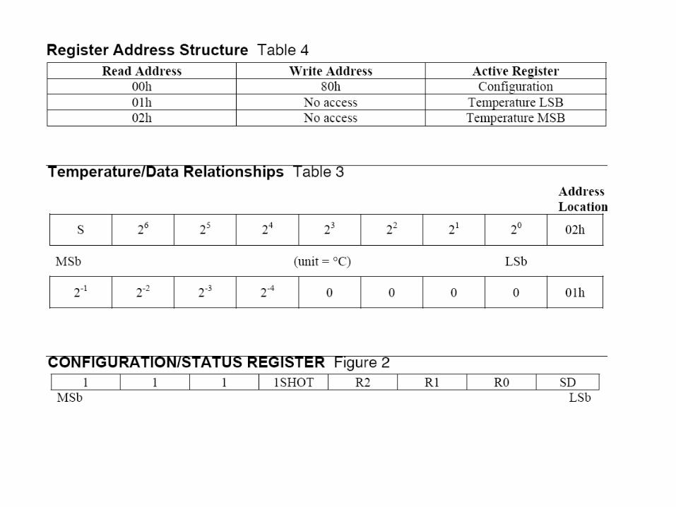
SPI Details
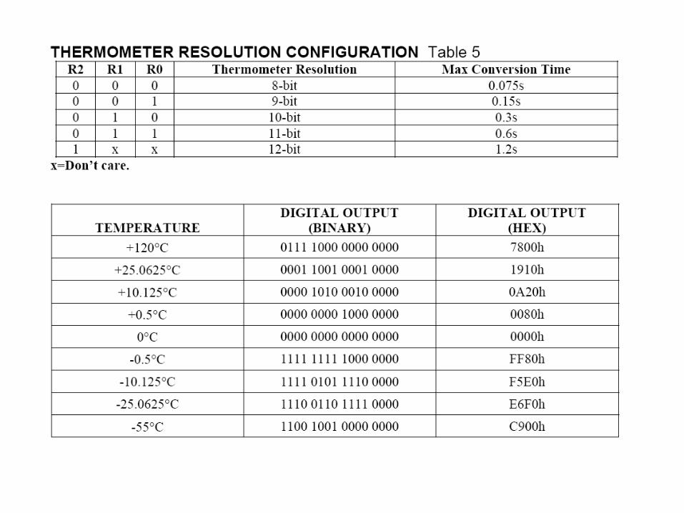
● Data read/written is device specific.
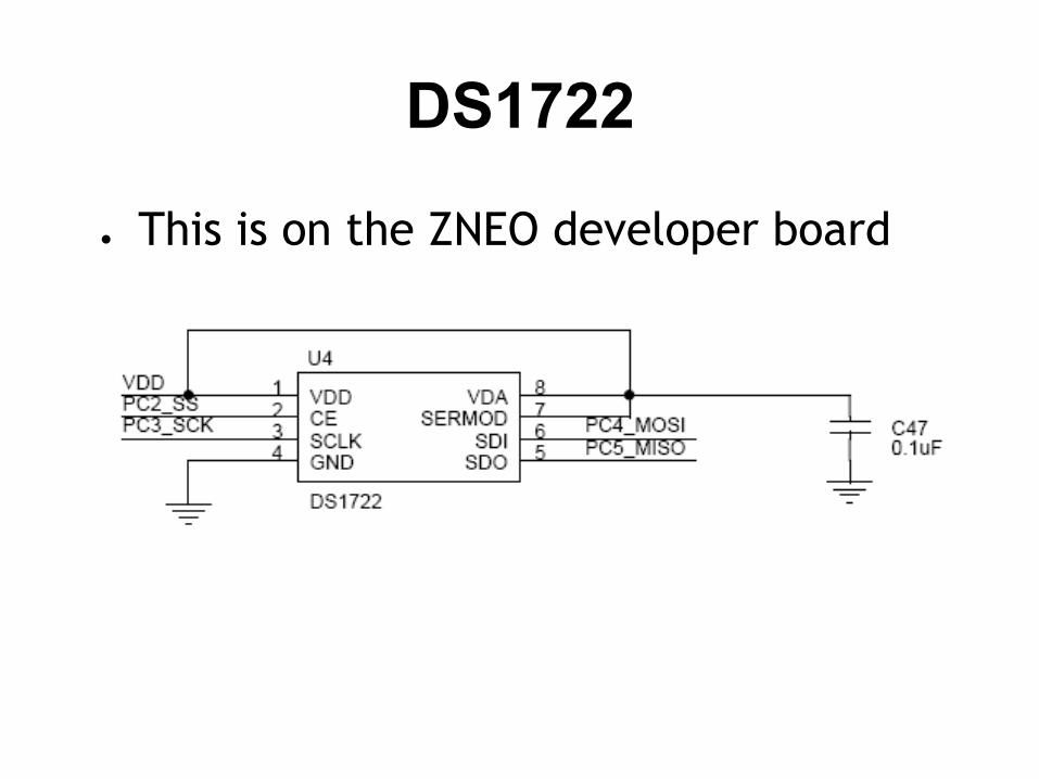
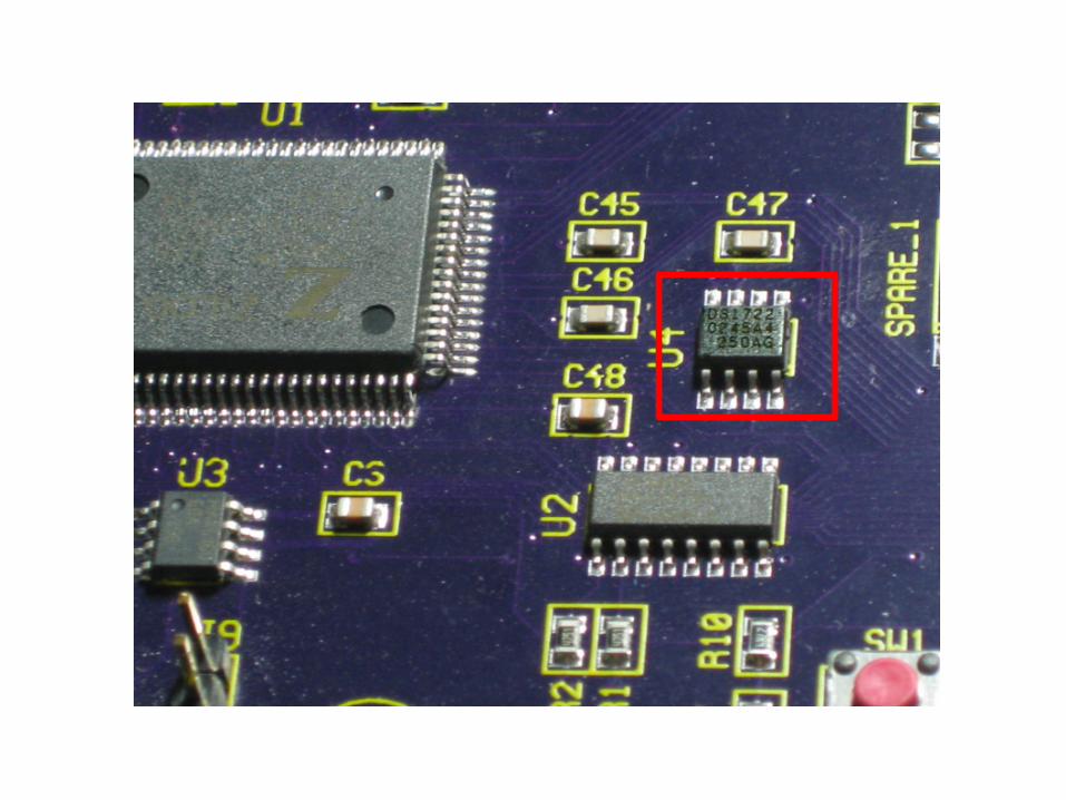
DS1722
● This is on the ZNEO developer board

What is a DS1722?
Use your mad Google skillz...
DS1722
Get the datasheet !
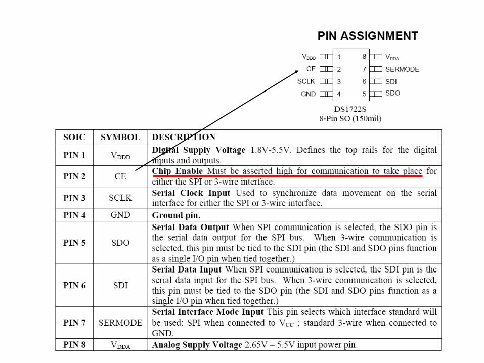
Note
If CE is active HIGHand /SS = active LOW
What do we do? How do we use this?
Note
● CE = active HIGH● /SS = active LOW
Use the SSPO bit of the ESPIMODE register to control this.

DS1722 Error
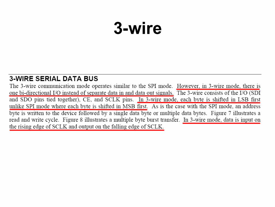
3-wire
3-Wire/Microwire
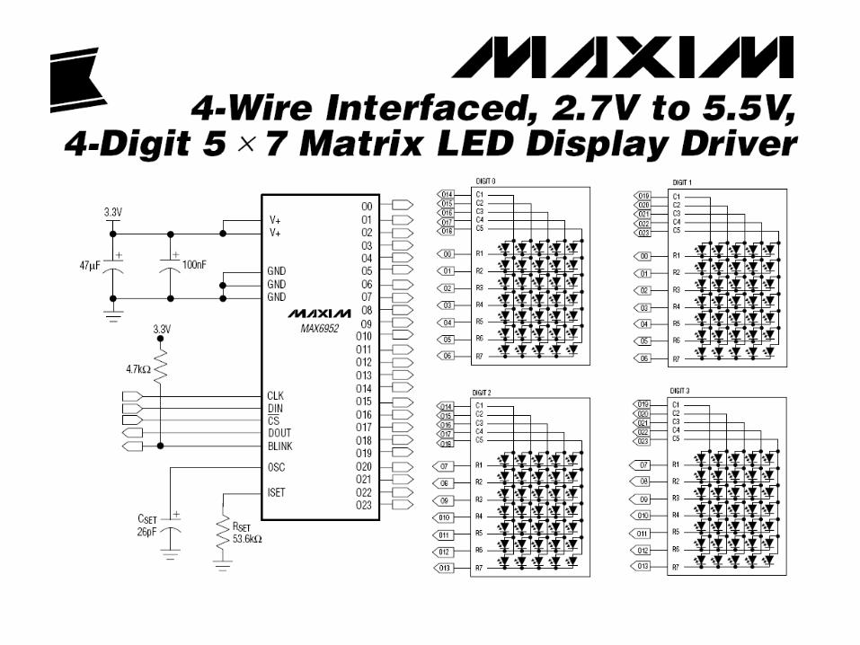
● The MICROWIRE protocol is essentially a subset of the SPI interface, specifically CPOL = 0 and CPHA = 0.
● The Maxim 3-wire interface is found on some ICs from Maxim. The data flow to and from the device is multiplexed on one pin (DQ) while SPI needs two separate signals (MOSI, MISO).
ESPI ExampleExample_SpiDs1722
● Read from the DS1722 SPI Temperature sensor
● SPI ● Serial Peripheral Interface● Synchronous● 3+1 wires● Master/Slave relationship● Data exchange of
Shift-registers