lecture 1410
TRANSCRIPT

8/2/2019 Lecture 1410
http://slidepdf.com/reader/full/lecture-1410 1/31
Chapter 31
Electromagnetic Oscillations and AlternatingCurrent
In this chapter we will cover the following topics:
-Electromagnetic oscillations in an LC circuit
-Alternating current (AC) circuits with capacitors
-Resonance in RCL circuits
-Power in AC-circuits-Transformers, AC power transmission
(31 - 1)

8/2/2019 Lecture 1410
http://slidepdf.com/reader/full/lecture-1410 2/31
Suppose this page is perpendicular to a uniform magnetic field
and the magnetic flux through it is 5Wb. If the page is turned by
30 around an edge the flux through it will be:
A. 2.5Wb
B. 4.3Wb
C. 5Wb
D. 5.8Wb
E. 10Wb
8/2/2019 Lecture 1410
http://slidepdf.com/reader/full/lecture-1410 3/31
A car travels northward at 75 km/h along a straight road in a
region where Earth’s magnetic field has a vertical component of
0.50 × 10⁻⁴ T. The emf induced between the left and right
side, separated by 1.7m, is:
A. 0
B. 1.8mV
C. 3.6mVD. 6.4mV
E. 13mV

8/2/2019 Lecture 1410
http://slidepdf.com/reader/full/lecture-1410 4/31
L
C The circuit shown in the figure consists of a capacitor
and an inductor . We give the capacitor an initial
chanrge and then abserve what happens. The capacitor will discharge th
C
L
Q
LC Oscillations
rough the inductor resulting in a time
dependent current .i
We will show that the charge on the capacitor plates as well as the current
1in the inductor oscillate with constant amplitude at an angular frequency
The total energy in the circuit is t
q i
LC
U
ω =
2 2
he sum of the energy stored in the electric field
of the capacitor and the magnetic field of the inductor. .2 2
The total energy of the circuit does not change with time. Thus
E B
q LiU U U
C dU
= + = +
2
2
2
2
0
0.1
0
dt
dU q dq di dq di d q Li i
dt C d
d q L
t dt dt q
dt dt dt C +
=
= + = = → → == (31 - 2)

8/2/2019 Lecture 1410
http://slidepdf.com/reader/full/lecture-1410 5/31
L
C
2
2
2
2
10 ( )
This is a homogeneous, second order, linear differential equation
which we have encountered previously. We used it to d
10
escribe
the simple harmonic oscillat
o
d q
L qdt C
d qq
dt LC
+ == →
+
eqs.1
22
20
with sol
r (SHO)
( )
ution: ( ) cos( )
d x x
dt
x t X t
ω
ω φ
+ =
= +
eqs.2
( )
If we compare eqs.1 with eqs.2 we find that the solution to the differential
equation that describes the LC-circuit (eqs.1) is:1
( ) cos where , and is the phase angle.
The current
q t Q t LC
ω φ ω φ = + =
( )sindq
i Q t dt
ω ω φ = = − +
( )( ) cosq t Q t ω φ = +
1 LC
ω =
(31 - 3)

8/2/2019 Lecture 1410
http://slidepdf.com/reader/full/lecture-1410 6/31
L
C
( )
( ) ( )
2 22
2 2 2 22 2
2
The energy stored in the electric field of the capacitor
cos2 2
The energy stored in the magnetic field of the inductor
sin sin2 2 2
The total energy
2
E
B
E B
q QU t
C C
Li L Q QU t t
C
U U U
QU
ω φ
ω ω φ ω φ
= = +
= = + = +
= +
= ( ) ( )2
2 2cos sin2
The total energy is constant;
Qt t C C
ω φ ω φ + + + =
energy is conserved
2
2
3The energy of the has a value of at 0, , , , ...2 2 2
3 5The energy of the has a value of at , , , ...
2 4 4 4
When is maximum is ze E B
Q T T t T C
Q T T T t
C
U U
=
=
electric field maximum
magnetic field maximum
Note : ro, and vice versa
(31 - 4)

8/2/2019 Lecture 1410
http://slidepdf.com/reader/full/lecture-1410 7/31
0t =
1
2
/ 8t T =
3
/ 4t T =
4
3 / 8t T =
5
5/ 2t T =
432
1
6
6
5 / 8t T =
3 / 4t T =
7 / 8t T =
7
8
7
8
(31 - 5)

8/2/2019 Lecture 1410
http://slidepdf.com/reader/full/lecture-1410 8/31
2
2
If we add a resistor in an RL cicuit (see figure) we must
modify the energy equation because now energy is
being dissipated on the resistor.
2 E B
dU i Rdt
qU U U
C
= −
= + = +
Damped oscillations in an RCL circuit
22
2
Li dU q dq di Li i R
dt C dt dt → = + = −
( )
2
2
2
/ 2
2
2 2
1 0 This is the same equation as that
of the damped harmonics o 0 which hscillator:
The a
as the solution
( ) co ngul r f s a
:
bt mm
dq di d q d q dqi L R qdt dt dt dt d
d x dxm b kx
dt dt
x t x e t
t C
ω φ −
+ + =
′= +
= → = → + + =
( )
2
2
2
2
/ 2 1( )
requency
For the damped RCL circuit the solut
cos
ion is:
The angular fre que
4
ncy
4
Rt L Rq
k bm m
t Qe t
LC L
ω
ω φ ω − ′ ′= + = −
′ = −
(31 - 6)

8/2/2019 Lecture 1410
http://slidepdf.com/reader/full/lecture-1410 9/31
/ 2 Rt LQe
−
/ 2 Rt LQe
−
( )q t Q
Q−
( )q t ( )/ 2( ) cos Rt Lq t Qe t ω φ
− ′= +
2
2
1
4
R
LC Lω ′ = −
/ 2
2
2
The equations above describe a harmonic oscillator with an exponetially decaying
amplitude . The angular frequency of the damped oscillator
1is always smaller than the angular f
4
Rt LQe
R
LC Lω
−
′ = −
2
2
1requency of the
1undamped oscillator. If the term we can use the approximation
4
LC R
L LC
ω
ω ω
=
′ ≈=
(31 - 7)

8/2/2019 Lecture 1410
http://slidepdf.com/reader/full/lecture-1410 10/31
A battery for which the emf is constant generates
a current that has a constant direction. This type
of current is known as " " or " "
In chapter 30 we encountered a d
Alternating Current
dcdirect current
ifferent type
of sourse (see figure) whose emf is:
sin sin where , is the area of the generator
windings, is the number of the windings, is the angular frequency of the
rotation of the windings, and is the magnetic field.
m m NAB t t NAB A
N
B
ω ω ω ω
ω = = =E E E
This type of generator
is known as " " or " " because the emf as well as the current
change direction with a frequency 2 . In the US 60 Hz.
Almost all commercial electrical
f f πω = =acalternating current
power used today is ac even though the
analysis of ac circuits is more complicated than that of dc circuits.
The reasons why ac power was adapted will be discussed at the end of this
chapter.
(31 - 8)
sinm t ω =E E

8/2/2019 Lecture 1410
http://slidepdf.com/reader/full/lecture-1410 11/31
L
C
Our objective is to analyze the circuit shown in the
figure ( circuit). The discussion will be greatly
simplified if we examine what happens if we connect
each of the three elem
RCL
Three Simple Circuits
ents ( , , and ) separately
to an ac generator.
R C L
From now on we will use the standard notation for ac circuitanalysis. Lower case letters will be used to indicate the
values of ac quantities. Upper case letters
will be used
A convention
instantaneous
( )
to indicate the constant amplitudes of ac quantities.
Example: The capacitor charge in an LC circuit was written as:cos
The symbol is used for the instantaneous value of the charge
The symbol
q Q t
q
ω φ = +
is used for the constant amplitude of Q q
(31 - 9)

8/2/2019 Lecture 1410
http://slidepdf.com/reader/full/lecture-1410 12/31
In fig.a we show an ac generator connected to a resistor
From KLR we have: 0 sin
The current amplitude
The voltage across is equal to sin
The voltage
m
R R
m R
R m
R
i R i t R R
I R
v R t
ω
ω
− = → = =
=
A resistive load
EEE
E
E
amplitude is equal toThe relation between the voltage and
current amplitudes is:
In fig.b we plot the resistor current and the
resistor voltage as function of time t.Both quanti
m
R
R
R RV I R
i
v
=
E
ties reach their maximum values
at the same time. We say that voltage and
current are .in phase
(31 - 10)
R RV I R=

8/2/2019 Lecture 1410
http://slidepdf.com/reader/full/lecture-1410 13/31
A convenient method for the representation of ac
quantities is that of phasors
The resistor voltage and the resistor current are represented
by rotating vectors known as phasors using the following conventions:
Phasors rotate in the counterclockwise direction with angula
R Rv i
1. r speed
The length of each phasor is proportional to tha ac quantity amplitude
The projection of the phasor on the vertical axis gives the instantaneous
value of the ac quantity.
The rotation
ω
2.
3.
4. angle for each phasor is equal to the phase of the
ac quantity ( in this example)t ω (31 - 11)
8/2/2019 Lecture 1410
http://slidepdf.com/reader/full/lecture-1410 14/31
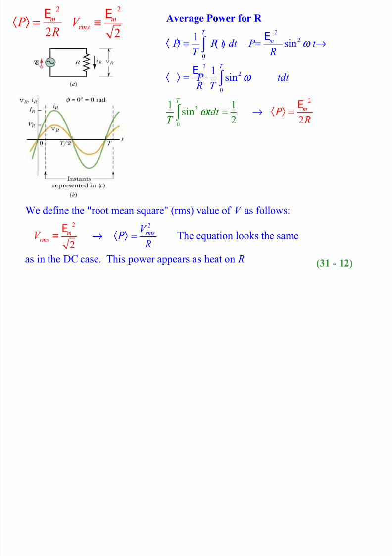
2 2
We define the "root mean square" (rms) value of as follows:
The equation looks the same
as in the DC case. This power appears a
s
2
heat on
rmsmrms
V
V P
R
R
V ≡ → ⟨ ⟩ =E
2
0
2
2
0
22
0
2
1( ) sin
1
1
si
1sin
n
22
T
m
T m
m
T
P P t dt P t T R
td
P tdt R
t T
T
P R
ω
ω
ω
⟨ ⟩ = = →
⟨
⟨ ⟩ =
⟩
=
=
→
∫
∫
∫
Average Power for R
E
E
E
2
2
m P R
⟨ ⟩ =E
2
2
mrmsV ≡
E
(31 - 12)

8/2/2019 Lecture 1410
http://slidepdf.com/reader/full/lecture-1410 15/31
( )
In fig.a we show an ac generator connected to a
capacitor
From KLR we have: 0
sin
cos sin 90
The voltage amplitude equal to
The current am
C
C m
C C m
C m
C
qC
q C C t
dqi C tdt t
dt
V
ω
ω ω ω
− = →
= =
= = = + °
A capacitive load
E
E E
E
E
plitude1/
The quantity is known as the
In fig.b we plot the capacitor current and the capacitor
voltage as function of time t
1
. The current the
v
/
C C
C
C
C
C
V I CV
C
i
v
X C ω
ω ω
= =
=
leads
capacitive reactance
oltage by a quarter of a period. The voltage and
current are .°out of phase by 90
O ω
C X
(31 - 13)
1
C
X C ω =

8/2/2019 Lecture 1410
http://slidepdf.com/reader/full/lecture-1410 16/31
2
2
2
0 0
sin cos
sin 22
1 1( ) = sin 2 0
2
A capacitor does not dissipate any power
on the average. In some parts o
2sin cos sin 2
h
f t
mC C
C
m
C
T T
m
C
P V I t t X
P t X
P P t dt tdt T X T
θ θ θ
ω ω
ω
ω
= =
→ =
⟨ ⟩ = =
=
∫ ∫
Average Power for C
Note :
E
E
E
e cycle it absorbes
energy from the ac generator but at the rest of the cycle
it gives the energy back so that on the average no
power is used!
0C P =
(31 - 14)

8/2/2019 Lecture 1410
http://slidepdf.com/reader/full/lecture-1410 17/31
( )
In fig.a we show an ac generator connected to an inductor
From KLR we have: 0 sin
sin cos sin 90
The voltage amplitude equa
m L L
m m m L L
L
L
di di L t
dt dt L L
i di tdt tdt t L L L
V
ω
ω ω ω ω ω
− = → = =
= = = − = − °∫ ∫
An inductive load
EEE
E E E
l to
The current amplitude
The quantity is known as the
In fig.b we plot the inductor current and the
inductor voltage as function of time t.
The current
m
L
L
L
L
L
V
I L
i
v
X L
ω
ω
==
E
inductive reactance
the voltage by a
quarter of a period. The voltage and
current are .°
lags behind
out of phase by 90
O
ω
L X
(31 - 15)
L X Lω =

8/2/2019 Lecture 1410
http://slidepdf.com/reader/full/lecture-1410 18/31
2
2
2
0 0
Power sin cos
sin22
1 1( ) = sin 2 0
2A inductor does not dissipate any power
on
2sin cos sin 2
the average. In some p rt
a s
m L L
L
m
L
T T
m
L
P V I t t
X
P t X
P P t dt tdt
T X T
ω ω
ω
ω
θ θ θ
= = −
→ = −
⟨ ⟩ ≡ − =
=
∫ ∫ Note :
E
E
E
Average Power for L
of the cycle it absorbes
energy from the ac generator but at the rest of the cycle
it gives the energy back so that on the average no
power is used!
0 L P =
(31 - 16)

8/2/2019 Lecture 1410
http://slidepdf.com/reader/full/lecture-1410 19/31
Circuitelement AveragePower Reactance Phase of current Voltage amplitude
Resistor
R
Current is in phase with the voltage
Capacitor
C
Current leads voltage by a quarter of a period
Inductor
L
Current lags behind
voltage by a quarter of a period
1C X
C ω =
L X Lω =
R RV I R=
C C C C
I V I X
C ω = =
L L L LV I X I Lω = =
R
SUMMARY
2
2
m R P
R⟨ ⟩ =
E
0C P ⟨ ⟩ =
0 L P ⟨ ⟩ =
(31 - 17)

8/2/2019 Lecture 1410
http://slidepdf.com/reader/full/lecture-1410 20/31
An ac generator with emf is connected to
an in series combination of a resistor , a capacitor
and an inductor , as shown in the figure. The phasor
for the ac genera
sinm
R C
L
t ω =The series RCL circuit
E E
( )
tor is given in fig.c. The current in
this circuit is described by the equation: sini I t ω φ = −( )sini I t ω φ = −
The current is for the resistor, the capacitor and the inductor
The phasor for the current is shown in fig.a. In fig.c we show the phasors for the
voltage across , the voltage across R C
i
v R v C
common
, and the voltage across .
The voltage is in phase with the current . The voltage lags behind
the current by 90 . The voltage leads ahead of the current by 90 .
L
R C
L
v L
v i v
i v i° °
(31 - 18)

8/2/2019 Lecture 1410
http://slidepdf.com/reader/full/lecture-1410 21/31
O
A B
Kirchhoff's loop rule (KLR) for the RCL circuit: . This equation
is represented in phasor form in fig.d. Because and have opposite directions
we combine the two in a single phasor
R C L
L C
L
v v v
V V
V
= + +E
( ) ( ) ( ) ( )
( )
( )
2 2 2 22 2 2 2
22
22
. From triangle OAB we have:
The denominator is known as the " "
of the circuit. The current amplitude
C
m R L C L C L C
m
L C
m L C
V
V V V IR IX IX I R X X
I Z R X X
Z R X X I
− = + − = + − = + − →
=+ −
= + − → =
E
E
E
impedance
2
2
1
m
Z
I
R L C ω ω
=
+ −
E
( )22 L C Z R X X = + −
m I Z
= E
( )sini I t ω φ = −
(31 - 19)

8/2/2019 Lecture 1410
http://slidepdf.com/reader/full/lecture-1410 22/31
O
A B
From triangle OAB we have: tan
We distinguish the following three cases depending on the relative values
of and .
0 The current phasor lags behind the generat
L C L C L C
R
L L
L C
V V IX IX X X V IR R
X X
X X
φ
φ
− − −= = =
> → >1. or phasor.The circuit is more inductive than capacitive
0 The current phasor leads ahead of the generator phasor
The circuit is more capacitive than inductive
0 The current phaso
C L
C L
X X
X X
φ
φ
> → <
= → =
2.
3. r and the generator phasor are in phase
( )sini I t ω φ = −
( )22 L C Z R X X = + −
L X Lω =
tan L C X X R
φ −=
1 C X
C ω =
(31 - 20)

8/2/2019 Lecture 1410
http://slidepdf.com/reader/full/lecture-1410 23/31
Fig.a and b: 0
The current phasor lags behindthe generator phasor. The circuit is more
inductive than capacitive
L C X X φ > → >1.
Fig.c and d: 0 The current phasor leads ahead of the generator
phasor. The circuit is more capacitive than inductive
Fig.e and f: 0 The current phasor and the generator ph
C L
C L
X X
X X
φ
φ
> → <
= → =
2.
3. asor are
in phase (31 - 21)
R

8/2/2019 Lecture 1410
http://slidepdf.com/reader/full/lecture-1410 24/31
In the RCL circuit shown in the figure assume that
the angular frequency of the ac generator can
be varied continuously. The current amplitude
in the circuit is given by the equation:
m I
ω
=
Resonance
E
2
2
The current amplitude1
1has a maximum when the term 0
1This occurs when
R LC
LC
LC
ω ω
ω ω
ω
+ −
− =
=
The equation above is the condition for resonance. When its is satisfied
A plot of the current amplitude as function of is shown in the lower figure.
This plot is known as a "
mres I
R
I ω
=E
resonance c "urve
mres I
R=
E1
LC ω =
(31 - 22)
2E

8/2/2019 Lecture 1410
http://slidepdf.com/reader/full/lecture-1410 25/31
2
We already have seen that the average power used by
a capacitor and an inductor is equal to zero. The
power on the average is consumed by the resistor.
The instantaneous power P i=
Power in an RCL ciruit
( )
( )
2
0
222 2
0
sin
1
The average power
1sin
2
cos
The term cos in the equation above is known as
the "
T
avg
T
avg rms
rmsavg rms rms rms rms rms rms rms
R I t R
P Pdt T
I R P I R t dt I R
T
R P I RI I R I I Z Z
ω φ
ω φ
φ
φ
= −
=
= − = =
= = = =
∫ ∫
E
E E
power fac " of the circuit. The average
power consumed by the circuit is maximum
when 0φ =
tor
2
avg rms P I R= cosavg rms rms P I φ = E (31 - 23)

8/2/2019 Lecture 1410
http://slidepdf.com/reader/full/lecture-1410 26/31
Power Station
Transmission lines
rms=735 kV , I rms = 500
A
home
110 V
T1T2
Step-up
transformer
Step-down
transformer
R = 220Ω
1000 km=l
2
The resistance of the power line . is fixed (220 in our example)
Heating of power lines This parameter is also fixed
( 55 MW in our exa
heat rms
R R A
P I R
ρ = Ω
=
Energy Transmission Requirements
l
mple)
Power transmitted (368 MW in our example)In our example is almost 15 % of and is acceptable
To keep we must keep as low as possible. The only wa
trans rms rms
heat trans
heat rms
P I P P
P I
=E
y to accomplish this
is by . In our example 735 kV. To do that we need a device
that can change the amplitude of any ac voltage (either increase or decrease)
rms rms =increasing E E
(31 - 24)

8/2/2019 Lecture 1410
http://slidepdf.com/reader/full/lecture-1410 27/31
The transformer is a device that can change
the voltage amplitude of any ac signal. It
consists of two coils with different number
of turns wound around a common iron core.
The transformer
The coil on which we apply the voltage to be changed is called the " " and
it has turns. The transformer output appears on the second coils which is knownas the "secondary" and has turns
P
S
N N
primary
. The role of the iron core is to insure that the
magnetic field lines from one coil also pass through the second. We assume that
if voltage equal to is applied across the primary then a voltag P V e appears
on the secondary coil. We also assume that the magnetic field through both coils
is equal to and that the iron core has cross sectional area A. The magnetic flux
through the primary
S
P
V
B
Φ ( )
The flux through the secondary ( )
P P P P
S
S S S S
d dB N BA V N A
dt dt
d dB N BA V N A
dt dt
Φ= → = − = −
ΦΦ = → = − = −
eqs.1
eqs.2
(31 - 25)
V V

8/2/2019 Lecture 1410
http://slidepdf.com/reader/full/lecture-1410 28/31
( )
( )
If we divide equation 2 by equation 1 we get:
P
S P
P P P P
S S S S S
S S S
P P S P P
d dB N BA V N A
dt dt
d dB N BA V N A
dt dt
dB N A
V N dt dBV N
N A
V
N
dt
V
N
ΦΦ = → = − = −
ΦΦ = → = − = −
−= =
−=→
eqs.1
eqs.2
The voltage on the secondary
If 1 We have what is known a " " transformer
If 1 We have what is known a " " transformer
Both types of tran
S S P
P
S S P S P
P
S S P S P
P
N V V
N
N N N V V
N
N N N V V
N
=
> → > → >
< → < → <
step up
step down
sformers are used in the transport of electric power over large
distances.
S P
S P
V V
N N =
(31 - 26)
V V
8/2/2019 Lecture 1410
http://slidepdf.com/reader/full/lecture-1410 29/31
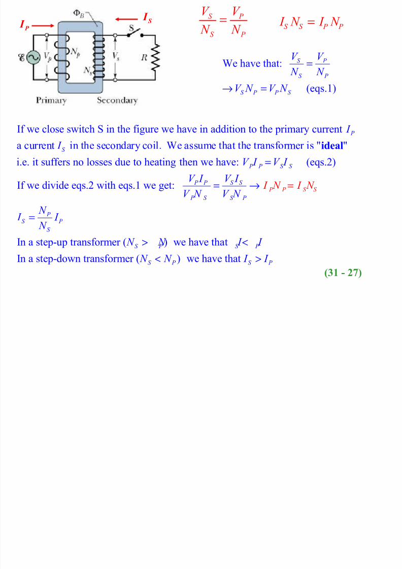
P I S I
If we close switch S in the figure we have in addition to the primary current
a current in the secondary coil. We assume that the transformer is " "
i.e. it suffers no losses due to heating
P
S
I
I ideal
then we have: (eqs.2)
If we divide eqs.2 with eqs.1 we get:
In a step-up transformer ( ) we have that
In a step-down transformer ( )
P P S
P P S S
S S P P
P S S P
P S P
S
S P S P
S P
S
V I V I
V I V I
V N V N
N I I
N
N
I N I N
N I I
N N
=
= →
=
><
=
<we have that S P I I >
We have that:
(eqs.1)
S P
S P
S P P S
V V
N N
V N V N
=
→ =
S P
S P
V V
N N =
S S P P I N I N =
(31 - 27)

8/2/2019 Lecture 1410
http://slidepdf.com/reader/full/lecture-1410 30/31
Hitt
A generator supplies 100 V to the primary coil of a
transformer. The primary has 50 turns and the
secondary has 500 turns. The secondary voltage is:A. 1000 V
B. 500 V
C. 250 V
D. 100 V
E. 10V

8/2/2019 Lecture 1410
http://slidepdf.com/reader/full/lecture-1410 31/31
hitt
The main reason that alternating current replaced
direct current for general use is:
A. ac generators do not need slip ringsB. ac voltages may be conveniently transformed
C. electric clocks do not work on dc
D. a given ac current does not heat a power line asmuch as the same dc current
E. ac minimizes magnetic effects