lecture 4: renewable energy syahrul ashikin azmi ppkse
TRANSCRIPT

LECTURE 4:LECTURE 4:RENEWABLE ENERGYRENEWABLE ENERGY
Syahrul Ashikin AzmiSyahrul Ashikin Azmi
PPKSEPPKSE

An overview.. An overview..
• Renewable energy is the production of electricity, transport fuel or process heat from self-renewing energy sources such as sunlight, wind, flowing water, the earth’s internal heat, biomass such as energy crops, agricultural and industrial waste.
• Renewable energy technologies include photovoltaic, solar thermal, wind turbines, hydro power, wave and tidal power, biomass-derived fuels and biomass-fired generation.
• Renewable energy systems generate virtually no waste or pollutants that can cause health and environmental problems such as acid rain, urban smog, greenhouse effect.

Renewable energy technologiesRenewable energy technologies
• Photovoltaic• Biomass
• Hydropower• Wind turbines

PHOTOVOLTAIC MATERIALPHOTOVOLTAIC MATERIALAND ELECTRICAL AND ELECTRICAL CHARACTERISTICCHARACTERISTIC

IntroductionIntroduction • A material or device that capable of converting
energy in photons of light into electrical voltage and current – photovoltaic.
• Photovoltaic use semiconductor materials to convert sunlight into electricity.
• Basic photovoltaic device is crystalline silicon.• As long as solar cell is exposed to photons with
energies above the band-gap energy, hole-electron pairs will be created.
• The problem is electron can fall back into a hole (recombination) causing both charge carriers to disappear.
• In PV, avoiding the problem by creating electric field within semiconductor itself that pushes electron in one direction and holes in the other.

P-n junction diodeP-n junction diode• P-n junction diode: If we apply voltage, Vd across diode
terminal, forward current flow from p-side to n-side. If diode in reverse direction, only a very small (≈10-12 A/cm2) reverse saturation current, I0 will flow.
• V-I characteristic curve for p-n junction diode is described by the following Shockley diode equation:
• Where Id is diode current in the direction of the arrow, Vd is voltage across diode terminal from p to n-side, I0 is reverse saturation current, q is electron charge (1.602 x 10⁻¹⁹C), k is Blotzmann’s constant (1.381 x 10⁻²³ J/K) and T is the junction temperature (K).
• A junction temperature of 25oC is often used as a standard, so diode equation becomes:
)1( /0 kTqV
ddeII
CateII oVd
d 25)1( 9.380

• A p-n junction diode allows current to flow easily from p-side to n-side, but not in reverse.

Generic photovoltaic cellGeneric photovoltaic cell• Simplest equivalent circuit for a photovoltaic cell
– Consists of diode parallel with ideal current source. Ideal current source delivers current in proportion to solar flux to which it is exposed.
A simple equivalent circuit for a PV cell consists of a current source driven by sunlight in parallel with a real diode.

• 2 conditions for actual PV and its equivalent circuit:– Current flows when the terminals are shorted together, short-circuit
current, ISC
– Voltage across terminal when the leads are left open, open-circuit voltage, VOC.
• Voltage and current equation are:
• When the leads from PV cell are left open, I=0 and we can find VOC:
• At 250C, these above equation becomes:
• In both equations, ISC is directly proportional to solar insolation (radiation), which means that we can easily plot sets of PV I-V curves for varying sunlight.
dSC III )1( /
0 kTqVSC eIII
1
0I
IIn
q
kTV SCOC
)1( 9.380 V
SC eIII
10257.0
0I
IInV SC
OC

• 2 important parameters for PV are short-circuit current and open-circuit voltage.

Photovoltaic I-V characteristic Photovoltaic I-V characteristic curvecurve
• Figure below show I-V relationship for a PV cell when it is dark (no illumination) and light (illuminated). The dark curve is just diode curve turned upside-down. The light curve is the dark curve plus ISC.

Example 1
• Consider a 100-cm2 PV cell with reverse current,I0=10-12 A/cm2. In full sun, it produces ISC of 40mA/cm2 at 250C. Find VOC at full sun and again for 50% sunlight. Plot the results.

Solution example 1Solution example 1
• The reverse saturation current, I0=10-12 A/cm2 x 100cm2 = 1x10⁻¹⁰A.
• At full sun, ISC =0.040A/cm2 x 100cm2= 4.0A.
• VOC is:
• Since short-current current is proportional solar intensity, at half sun ISC=2A and VOC is:
VInI
IInV SC
OC 627.0110
40257.010257.0
100
VInI
IInV SC
OC 610.0110
20257.010257.0
100

• Plotting the result

More accurate equivalent circuit for a More accurate equivalent circuit for a PV cellPV cell
• Consider the impact of shading on a string of cells wired in series. If any cell in the string is in dark (shaded), it produces no current and diode is reverse-biased. Thus, no power will be delivered to the load if any of the cells are shaded.

• Figure below shows a PV equivalent circuit including parallel leakage resistance, Rp. The ideal ISC deliver current to diode, Rp and load:
pdSC R
VIII )(

• From the equation, at any given voltage, the parallel leakage resistance causes load current for the ideal model to be decreased by V/Rp as
shown in graph below.

• An equivalent circuit with series resistance, Rs shown below.
• Analysis part of the circuit.
• And then add the impact of Rs,
• To give
)1( /0 kTqV
SCdSCdeIIIII
Sd IRVV
1
)(exp0 kT
IRVqIII S
SC

• Adding series resistance to the PV equivalent circuit causes the voltage at any given current to shift to the left by ΔV=IRS.

• Finally, PV equivalent circuit including both series and parallel resistance.
• The equation for current and voltage is:
p
SSSC R
IRV
kT
IRVqIII 1
)(exp0
CatR
IRVeIII
p
SIRVSC
S 0(9.380 251

• Unfortunately, the equation is a complex equation for which there is no explicit solution for either V or I.
• Apply KCL to the node in figure above, we can write:
• Rearrange and substituting Shockley diode equation at 250C gives:
• Voltage across an individual cell can be found from:
PdSC IIII
P
dVSC R
VeIII d )1( 9.38
0
Sd IRVV

• Series and parallel resistance in the PV equivalent circuit decrease both voltage and current delivered. To improve cell performance, high RP and low RS are needed.

From cells to a moduleFrom cells to a module• An individual cell produces only about 0.5-0.6V, so it is
a rare application of using just a single cell in any case.• So, the basic building block for PV applications used is
a module consists of a number of pre-wired cells in series, all encased in tough, weather-resistant packages.
• A typical module has 36 cells in series and often designated as a ’12-V modules’. 72-cell modules referred as 24-V modules.
• Multiple modules can be wired in series to increase voltage and in parallel to increase current, the product of which is power.
• Important element in PV system design is deciding how many modules should be connected in series and how many in parallel to deliver whatever energy is needed.
• Such combinations of modules are referred to as an array.

• When PV are wired in series, they carry the same current and their voltages add as shown in figure below.
• To find overall module voltage, Vmodule is:)(mod Sdule IRVnV

• For cell wired in series, their voltages at any given current add. A typical module will have 36 cells.

Example 2Example 2• A PV module is made up to 36 identical cells,
all wired in series. With 1-sun insolation (1kW/m2), each cell has ISC=3.4A and at 250C its I0=6x10⁻¹⁰ A. Rp=6.6Ω and Rs=0.005Ω.
a. Find the voltage, current and power delivered when the junction voltage of each cell is 0.50V.
b. Set up a spreadsheet for I and V and present a few lines of output to show how it works.

Solution example 2Solution example 2a. Using Vd=0.5V and the other data gives current:
Ae
R
VeIII
P
dVSC
d
16.36.6
5.0)1(1064.3
)1(
5.09.3810
9.380
VIRVnV Sdule 43.17)005.016.35.0(36)(mod
WIVP ule 5516.343.17mod

A spreadsheet look something like the following:
Notice that: the maximum power for this module is atI=3.16A, Vmodule=17.43V and P=55.08W.

From modules to arraysFrom modules to arrays• Arrays are made up of some combination of series
and parallel modules to increase power.• For modules in series, I-V curves are added along
the voltage axis. So, at any given current (which flows through each of modules), the total voltage is the sum of individual module voltages.

• For modules in parallel, the same voltage is across each module and the total current is the sum of the currents. At any given voltage, I-V curve of parallel combination is the sum of individual module current at that voltage.
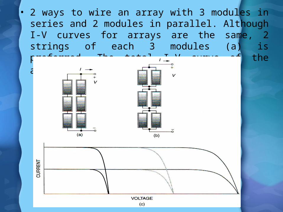
• 2 ways to wire an array with 3 modules in series and 2 modules in parallel. Although I-V curves for arrays are the same, 2 strings of each 3 modules (a) is preferred. The total I-V curve of the array is shown in figure below.

PV I-V curve under standard test PV I-V curve under standard test conditions (STC)conditions (STC)
• A single PV module is connected to load as shown in figure below. The load may be a dc motor driving a pump or a battery.
• Before load connected, module is in the sun will produce VOC but no current will flow.
• If the terminals are shorted, ISC will flow but the output voltage is zero.
• In both cases, no power is delivered by the module and no power received by the load.
• When the load is connected, current and voltage will result and power is delivered.
• To figure how much power, we have to consider I-V curve of the module as well as I-V curve of the load.


• Figure below shows a generic I-V curve for PV module.
• At the two ends of I-V curve, the output power is zero since either current or voltage is zero at that point.
• The maximum power point (MPP) is spotted near the knee of I-V curve at which the product of current and voltage reaches its maximum.
• The voltage and current at MPP is designated as VR and IR.

• Manufacturer provide performance data under standard operating condition. Rated power denote as PDC,STC is the dc power measured under STC.

Impacts of temperature and insolation Impacts of temperature and insolation on I-V curveson I-V curves
• Manufacturers often provide I-V curves that show how curves shift as insolation and cell temperature changes.
• Figure below shows examples for Kyocera 120-W multicrystal-silicon module. As insolation drops, ISC drops proportionally. Decrease insolation also reduces VOC.

• As cell temperature increases, VOC decreases drastically eventhough ISC increases slightly.
• Cell vary in temperature not only because ambient temperature change, but also due to insolation on the cells change.
• For crystalline silicon cells, VOC drop about 0.37%, ISC increases by 0.05% and maximum power decrease by 0.5% for each degree Celsius increase in temperature.
• Only a small fraction of insolation hitting a module is converted to electricity and carried away, most of incident energy is absorbed and converted to heat.
• Manufacturer often provide an indicator called NOCT (nominal operating cell temperature) to account for changes in cell performance with temperature.
• NOCT is cell temperature in a module when ambient is 200C,solar irradiation is 0.8kW/m2 and windspeed is 1m/s.
• To calculate for other ambient conditions, use: SNOCT
TT ambcell
8.0
200

Example 3Example 3 • Estimate cell temperature, VOC and maximum power
output for 150W,BP2150S module under condition of 1-sun insolation and Tamb=300C. The module has a NOCT=470C and S=1kW/m2.
• Solution:
• From Table given, for this module at standard temperature, VOC=42.8V. Since VOC drops by 0.37%/0C, the new VOC will be:
• With maximum power expected to drop about 0.5%/0C, this module will deliver:
– Which is a significant drop of 19% from its rated power (150W).
CSNOCT
TT ambcell0
0
6418.0
204730
8.0
20
VVOC 7.36)]2564(0037.01[8.42
WP 121)]2564(005.01[150max

Shading impacts on I-V curvesShading impacts on I-V curves
• The output of PV module can be reduced dramatically even when a small portion of it is shaded.
• A single shaded cell can easily cut output power by more than half.
• External diode is added by the system designer or manufacturer to preserve the performance of PV modules.
• The main purpose of diode is to mitigate the impact of shading on PV I-V curves. Diode is connected in parallel with modules or blocks of cells within a module.

• In figure (a), all the cells are in the sun and since they are in series, the same current flow through each of them.
• In figure (b), the top cell is shaded and its ISC is reduced to zero. The voltage drop across Rp as current flow through it causes the diode to be reverse-biased, Id=0. So, the entire current flowing through the module must travel through both Rp and Rs in the shaded cell on its way to the load. The top cell, instead of adding to the output voltage actually reduces it.

• The output voltage of entire module, VSH with one cell shaded will drop to:
• VC is I(RS + RP). With all n cells in the sun and carrying I, the output voltage is V, so the voltage of the bottom n-1 cells will be:
• Combine both above equations:
• The drop in voltage ΔV at any given I, caused by shaded cell, is given by:
)(1 SpnSH RRIVV
Vn
nVn
1
1
)(1
SPSH RRIVn
nV
)(
)(1
1
SP
SPSH
RRIn
V
RRIVn
VVVV

• Since the parallel resistance, Rp is much greater than series resistance, Rs simplifies to:
• At any given current, I-V curve for the module with one shaded cell drops by ΔV. The huge impact can be seen by figure below.
PIRn
VV

Example 4Example 4
• The 36-cell PV module described in Example 3 had a Rp per cell=6.6Ω. In full sun and at current, I=2.14A the output voltage, V=19.41V. If one cell is shaded and this current stays the same, so:a) What would be the new module output voltage
and power?b) What would be the voltage drop across the
shaded cell?c) How much power would be dissipated in the
shaded cell?

Solution example 4Solution example 4a) The drop in module voltage will be:
– The new output voltage will be 19.41-14.66=4.75V.– Power delivered by the module with one cell shaded
would be:
– For comparison, in full sun the module is producing 41.5W.
b) All of 2.14A current goes through parallel plus series resistance (0.005Ω) of shaded cell, so the drop across the shaded cell will be:
(normally a cell in the sun will add about 0.5V to the module, this shaded cell subtracts over 14V from module)
VIRn
VV P 66.146.614.2
36
41.19
WVIP ule 17.1014.275.4mod
VRRIV SPc 14.14)005.06.6(14.2)(

c) The power dissipated in the shaded cell is voltage drop times current which is:
Most of power dissipated in the shaded cell is converted to heat, which can cause a local hot spot that may permanently damage the plastic laminates enclosing the cell.
WIVP c 2.3014.214.14

• Module under full-sun conditions and with one cell 50% shaded, one cell completely shaded and 2 cells completely shaded. The vertical line at 13V is a typical operating voltage for module charging a 12V battery. The impact of charging current is obviously severe. With just one cell shaded out of 36 in the module, the power delivered to the battery is decreased by about 2/3 of power delivered at full sun.
Bypass diodes for shade Bypass diodes for shade mitigationmitigation
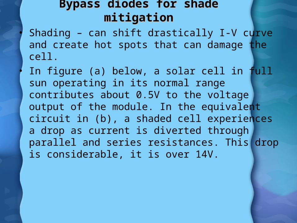
• Shading – can shift drastically I-V curve and create hot spots that can damage the cell.
• In figure (a) below, a solar cell in full sun operating in its normal range contributes about 0.5V to the voltage output of the module. In the equivalent circuit in (b), a shaded cell experiences a drop as current is diverted through parallel and series resistances. This drop is considerable, it is over 14V.


• The voltage drop in shaded cells can be corrected by adding a bypass diode across each cell as shown in figure.
• When a solar cell is in the sun, there is a voltage rise across the cell so the bypass diode is cut off and no current flow through it.
• When the solar cell is shaded, the drop that occur if the cell conducted current would turn on the bypass diode, diverting the current flow through that diode.
• The bypass diode, when it conducts, drops about 0.6V.
• So, the bypass diode controls the voltage drop across shaded cell and limit it to relatively modest 0.6V instead of large drop that may occur without it.


• Refer to the graph, PVs delivering charging current at about 65V to 60V battery bank. In full sun, about 3.3A are delivered to the batteries. When shaded cell without bypass diode, the current drop by one-third to about 2.25A. With bypass diode across shaded module, I-V curve is improved considerably.

• Figure below explain how bypass diode do their job. 5 modules wired in series, connected to battery that forces the modules to operate at 65V battery.
• In full sun, the modules deliver 3.3A at 65V. • When any of the cell shaded, they stop to produce
voltage and instead begin to act like resistors that cause voltage to drop as the other modules continue to push current through the string.
• Without a bypass diode to divert the current, the shaded module loses voltage. The other modules try to compensate by increasing voltage, but the net effect is that current in the whole string drops.
• If bypass diodes included, current will go around the shaded module and only a slight voltage drop across the whole modules.
• Bypass diode help current go around shaded or malfunctioning module within a string.
• This will improve the string performance but also prevent hot spots from developing in individual shaded cells.


Blocking diodesBlocking diodes
• When string of modules wired in parallel, a similar problem also arise when one of the strings is not performing well.
• A malfunctioning or shaded string can withdraw current from the rest of the array.
• By placing blocking diode (isolation diodes) at the top of each string, the reverse current drawn by a shaded string can be prevented.

• Blocking diodes prevent reverse current from flowing down malfunctioning or shaded strings.

Crystalline silicon technologiesCrystalline silicon technologies
• Currently, about 80% of all PV are thick cells and the remaining 20% are thin-film cells used in calculator, watches and other consumer electronics.
• PV technologies can be categorized into:i. Single crystal – dominant silicon technologyii. Multicrystalline – cell made up of a number of
relatively large area of single crystal grain (1mm to 10cm).
iii. Polycrystalline – many grains having dimensions of 1μm to 1mm. Example cadmium telluride.
iv. Microcrystalline – grain sizes less than 1μm.v. Amorphous – no single-crystal regions as in
amorphous silicon.