lecture #6: color tv interlacing fields€¦ · • our eyes average this out on a black and white...
TRANSCRIPT

D:\Home\ese488\Lectures\6_ColorTV\Lecture6_ColorTV.doc Page 1 of 22
Lecture #6: Color TV (Download Handout from Web Page)
Interlacing Fields:
Interlace Raster Scan
Illustration of scanning beam on CRT face during Interlace scan.
Interlaced Scan
Illustration of how Interlacing is accompolished.
(Even) (Odd)

D:\Home\ese488\Lectures\6_ColorTV\Lecture6_ColorTV.doc Page 2 of 22
Raster Scan Deflection Waveforms
Figure shows Horizontal & Vertical Sweep Voltage Waveforms, and their relative timing Relationships.
• Odd Fields start in the upper left corner and end in the bottom middle. • Even Fields start in the upper middle and end in the bottom right. • What is wrong with this picture?
o Only 10 lines/Field. o Vertical Retrace time should be 0.95ms (p.192 of Handout). That is the
time it takes to do 15 horizontal retraces.
247.5
495

D:\Home\ese488\Lectures\6_ColorTV\Lecture6_ColorTV.doc Page 3 of 22
Horizontal Sync Complex
Illustrating "Front Porch," "Sync Tip," "Back Porch" with Color Burst riding on it. The interval between the end of the sync tip & the start of the burst is sometimes refered to as the "Breeze -way." Note also, the "Burst Flag" (D.C. Restore clamp).
• 1 line = 63.5 us → Horizontal Refresh Rate 15750 Hz. • Horizontal Retrace Time = 1.5us + 4.7us + 4.7us = 10.9 us.

D:\Home\ese488\Lectures\6_ColorTV\Lecture6_ColorTV.doc Page 4 of 22
Raster Scan Synchronization Waveforms
NTSC/RS-170A, complete set of waveforms, including Composite Blanking. Note Color Subcarrier phasing (in red).

D:\Home\ese488\Lectures\6_ColorTV\Lecture6_ColorTV.doc Page 5 of 22
Waveforms from File: 8Bars.20MHz.bin
• Field 1 o Ends on a ½ line in the bottom middle of the screen
• Field 2 o Identify Odd or Even Field by finding the starting point for 6 high pulses
of ½ line duration followed by 6 low pulses of ½ line duration. o Vertical Retrace for 15 lines. o Starts on a ½ line o 247 ½ lines o Ends in the lower right corner o 15 + 247.5 = 262.5 lines * 63.5 us / line → 60 Hz Refresh for even fields.
Field 1 Start of Field 2 – Vertical Blanking Interval (15 lines)

D:\Home\ese488\Lectures\6_ColorTV\Lecture6_ColorTV.doc Page 6 of 22
• Field 2
o Ends on a full line in the lower right corner of the screen. • Field 1
o Vertical Retrace for 15 lines. o Starts on a full line o 247 ½ lines o Ends in the bottom middle of the screen o 15 + 247.5 = 262.5 lines * 63.5 us / line → 60 Hz Refresh for odd fields.
• 30 Hz refresh rate for interlaced image.
Field 2 Start of Field 1 – Vertical Blanking Interval

D:\Home\ese488\Lectures\6_ColorTV\Lecture6_ColorTV.doc Page 7 of 22
Quadrature Amplitude Modulation Trig Identities
( ) ( ) ( ) ( ) ( ) ( )( )
( ) ( )
( ) ( ) ( ) ( ) ( ) ( )( )
( ) ( )θφθφ
φθ
θφθφ
φθ
θφθφθφθφφφθθ
θφθφθφθφφφθθ
−++=
−+−=−+=
−++=
+++=++=
−−−+−+−−
−−−+−+−−
sin2
1sin
2
1
4
1
22sincos
cos2
1cos
2
1
4
1
22coscos
jjjjjjjj
jjjjjjjj
eeeejj
eeee
eeeeeeee
Modulation
( ) ( ) ( ) ( )φθφθ sincoscoscos 2211mod AAx +=
Demodulation – Cosine Channel
( ) ( ) ( ) ( ) ( ) ( ) ( )( ) ( ) ( ) ( ) ( )
( ) ( ) ( ) ( )
( ) ( ) ( ) ( ) ( )
( )11cosmod
2222111111
2211
222
11
2211modcosmod
cos
:Filter Pass LowAfter
2cos2
12sin
2
12cos
2
12cos
2
1cos
2sin2
1cos22cos
2
1
2
1cos2
sincoscos2coscos2
sincoscos2coscoscos2cos2*
θ
θφθφθφθφθ
φθφθ
φφθφθφφθφφθφ
Ax
AAAAA
AA
AA
AAxx
lpfde
de
=
−+++−+++=
+
+=
+=
+==
−−
−
Demodulation – Sin Channel
( ) ( ) ( ) ( ) ( ) ( )
( ) ( ) ( ) ( )
( ) ( ) ( ) ( ) ( )
( )22sinmod
2222221111
2211
22211modsinmod
cos
:Filter Pass LowAfter
2cos2
12cos
2
1cos2sin
2
12sin
2
1
2cos2
1
2
1cos22sin
2
1cos2
sincos2cossincos2sin2*
θ
θφθφθθφθφ
φθφθ
φθφφθφ
Ax
AAAAA
AA
AAxx
lpfde
de
=
−−+−+−++=
−+
=
+==
−−
−
D:\Home\ese488\Lectures\6_ColorTV\Lecture6_ColorTV.doc Page 8 of 22
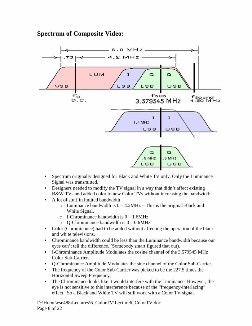
Spectrum of Composite Video:
• Spectrum originally designed for Black and White TV only. Only the Luminance
Signal was transmitted. • Designers needed to modify the TV signal in a way that didn’t affect existing
B&W TVs and added color to new Color TVs without increasing the bandwidth. • A lot of stuff in limited bandwidth
o Luminance bandwidth is 0 – 4.2MHz – This is the original Black and White Signal.
o I-Chrominance bandwidth is 0 – 1.6MHz o Q-Chrominance bandwidth is 0 – 0.6MHz
• Color (Chrominance) had to be added without affecting the operation of the black and white televisions.
• Chrominance bandwidth could be less than the Luminance bandwidth because our eyes can’t tell the difference. (Somebody smart figured that out).
• I-Chrominance Amplitude Modulates the cosine channel of the 3.579545 MHz Color Sub-Carrier.
• Q-Chrominance Amplitude Modulates the sine channel of the Color Sub-Carrier. • The frequency of the Color Sub-Carrier was picked to be the 227.5 times the
Horizontal Sweep Frequency. • The Chrominance looks like it would interfere with the Luminance. However, the
eye is not sensitive to this interference because of the “frequency-interlacing” effect. So a Black and White TV will still work with a Color TV signal.

D:\Home\ese488\Lectures\6_ColorTV\Lecture6_ColorTV.doc Page 9 of 22
o A color TV can remove the chrominance from the luminance with a comb filter (Moving Average of length 2).
• The Luminance looks like it would interfere with the Chrominance. But the eye isn’t sensitive to this either because of the “frequency-interlacing” effect.

D:\Home\ese488\Lectures\6_ColorTV\Lecture6_ColorTV.doc Page 10 of 22
Decomposition of Composite Video:
( ) ( ) ( ) ( ) ( ) ( )ttmttmtmtm ccIccQLv ωω cos*sin* ++≈
(Approximately because top bandwidth of I chrominance is filtered out causes the mIHh term to appear. Don’t worry about that right now.) mL(t):
1. Low Pass Filter mv(t) and use comb filter to remove chrominance. mQ(t):
1. Band Pass Filter mv(t) from 2 – 4.2MHz, and multiply by sine, amplitude = 2
( ) ( )( ) ( ) ( ) ( ) ( )[ ] ( )( ) ( ) ( ) ( ) ( ) ( ) ( )( ) ( ) ( ) ( ) ( ) ( ) ( ) ( )ttmttmtmttmtm
tttmttmttm
tttmttmtm
ttmttz
ccIccQQccLL
ccccIccQccL
ccccIccQL
ccvcc
ωωωωωωω
ωωωωω
2sin*2cos*2sin*
sin*cos2*sin2*sin2*
sin2*cos*sin*
sin2*)sin(2*)(
2.42_2.42_
22.42_
2.42_
2.42_
+−++=
++=
++=
=
−−
−
−
−
2. Final low pass at 600KHz eliminates double frequency terms. 3. We are left with mQ(t) and mL_2-4.2(t). 4. mL_2-4.2(t) gets bandlimited to 600KHz but doesn’t interfere with mQ(t) because
of the “frequency-interlacing” effect.

D:\Home\ese488\Lectures\6_ColorTV\Lecture6_ColorTV.doc Page 11 of 22
mI(t): 1. Band Pass Filter mv(t) from 2 – 4.2MHz, and multiply by cosine, amplitude = 2
( ) ( )( ) ( ) ( ) ( ) ( )[ ] ( )( ) ( ) ( ) ( ) ( ) ( )( ) ( ) ( ) ( ) ( ) ( ) ( ) ( )ttmtmttmttmtm
ttmtttmttm
tttmttmtm
ttmttz
ccIIccQccLL
ccIccccQccL
ccccIccQL
ccvcc
ωωωωωωω
ωωωωω
2cos*2sin*2cos*
cos2*sin*)cos(2*cos2*
cos2*cos*sin*
cos2*)cos(2*)(
2.42_2.42_
22.42_
2.42_
2.42_
++++=
++=
++=
=
−−
−
−
−
2. Final low pass at 1.6MHz eliminates double frequency terms. 3. We are left with mI(t) and mL_2-4.2(t). 4. mL_2-4.2(t) gets bandlimited to 1.6MHz but doesn’t interfere with mI(t) because of
the “frequency-interlacing” effect.

D:\Home\ese488\Lectures\6_ColorTV\Lecture6_ColorTV.doc Page 12 of 22
“Frequency-Interlacing” Effect in the Time Domain • The color sub-carrier is 227.5 times the horizontal sweep frequency. • This causes the phase of the color sub-carrier to flip 180
� for adjacent lines
(spatial phase reversal). • For example, shown below is the Color Sub-Carrier for 3 adjacent lines in the odd
field:
Line 1
Line 3 Line 1
Line 5 Line 3

D:\Home\ese488\Lectures\6_ColorTV\Lecture6_ColorTV.doc Page 13 of 22
• Since the carrier amplitude is +/- 1 on adjacent lines, the chrominance is multiplied by +/- 1 on adjacent lines.
• Our eyes average this out on a Black and White TV. • Averaging adjacent lines removes the Chrominace from the Luminance in the
Color TV. • The Color Sub-Carrier is also varies by 180
� frame to frame. That is, the phase of
the Color Sub-Carrier for Line1/Frame1 is 180� out of phase with the carrier for
Line1/Frame2 (temporal phase reversal). • For example, Line1/Frame2 starts 525 lines*227.5 periods/line = 119437.5
periods of the Color Sub-Carrier after Line1/Frame1. Line1/Frame1 is 180� out of
phase with the previous Line1/Frame2. • The figure below graphically shows this temporal and spatial phase reversals:

D:\Home\ese488\Lectures\6_ColorTV\Lecture6_ColorTV.doc Page 14 of 22
“Frequency-Interlacing” Effect in the Time Domain
• Let’s look at the spectrum for vertical bars on a Color TV to see what the “Frequency-Interacing” looks like.
• We will consider the case where the Luminance, I-Chrominance and Q-Chrominance signals are pure tones.
• For the Horizontals lines to repeat, these pure tones need to be harmonics of the horizontal sweep frequency. Why?
o N/Fo=63.5uS=1/Fh. So, Fo=N*Fh . • We will ignore the Sync Tip and the Color Burst for right now.
D:\Home\ese488\Lectures\6_ColorTV\Lecture6_ColorTV.doc Page 15 of 22
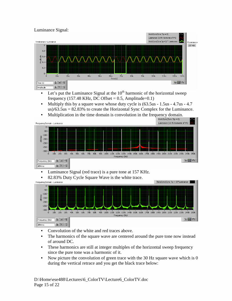
Luminance Signal:
• Let’s put the Luminance Signal at the 10th harmonic of the horizontal sweep
frequency (157.48 KHz, DC Offset = 0.5, Amplitude=0.1) • Multiply this by a square wave whose duty cycle is (63.5us - 1.5us - 4.7us - 4.7
us)/63.5us = 82.83% to create the Horizontal Sync Complex for the Luminance. • Multiplication in the time domain is convolution in the frequency domain.
• Luminance Signal (red trace) is a pure tone at 157 KHz. • 82.83% Duty Cycle Square Wave is the white trace.
• Convolution of the white and red traces above. • The harmonics of the square wave are centered around the pure tone now instead
of around DC. • These harmonics are still at integer multiples of the horizontal sweep frequency
since the pure tone was a harmonic of it. • Now picture the convolution of green trace with the 30 Hz square wave which is 0
during the vertical retrace and you get the black trace below:

D:\Home\ese488\Lectures\6_ColorTV\Lecture6_ColorTV.doc Page 16 of 22

D:\Home\ese488\Lectures\6_ColorTV\Lecture6_ColorTV.doc Page 17 of 22
Chrominance Signal:
• I-Chrominance Signal be 945 KHz sine wave (60th harmonic - White Trace
below, 0.2V Amplitude). • Q-Chrominance Signal be 394 KHz sine wave (25th harmonic - Red Trace below,
0.1V Amplitude). • The Green trace below is the Color Sub-Carrier which is 227.5 times the
Horizontal Sweep Frequency (Fh). • QAM the Color Sub-Carrier with the Chrominance Signal. This gives you peaks
at Fcc +/- the I-Chrominance Frequency and at Fcc +/- the Q-Chrominance Frequency (Blue trace below). The lower side band frequencies of the blue trace are at 227.5-60=167.5 * Fh and 227.5-25=202.5 * Fh. Note that the Upper Side band of the I-Chrominance signal has been filtered out to limit the bandwidth to 4.2MHz.
• Multiply this by a square wave with frequency Fh and duty cycle (63.5us - 1.5us - 4.7us - 4.7 us)/63.5us = 82.83% to create the Horizontal Sync Complex for the Chrominance. (Yellow trace above and below).
• Multiplication in the time domain is convolution in the frequency domain. • The convolution positions the harmonics of Fh between the harmonics of the
Luminance signal.

D:\Home\ese488\Lectures\6_ColorTV\Lecture6_ColorTV.doc Page 18 of 22
• Zoom in of harmonics of the near DC shows that they are interlaced between the
Luminance
• Now picture the convolution of yellow trace above with the 30 Hz square wave which is 0 during the vertical retrace and you get the red trace below:
• Interlacing in the Frequency domain makes it invisible to the human eye, so the Black and White TV will still work.

D:\Home\ese488\Lectures\6_ColorTV\Lecture6_ColorTV.doc Page 19 of 22
Using the Luminance and Chrominance signals from above, we get this picture (Test.20MHz.bin). ��

D:\Home\ese488\Lectures\6_ColorTV\Lecture6_ColorTV.doc Page 20 of 22
• Video Signal

D:\Home\ese488\Lectures\6_ColorTV\Lecture6_ColorTV.doc Page 21 of 22
• Decoded Luminance and Chrominance signals

D:\Home\ese488\Lectures\6_ColorTV\Lecture6_ColorTV.doc Page 22 of 22
• Red, Green, and Blue Signals.
References:
• www.ntsc-tv.com • Section 4.9 of Dr. Morley’s textbook