lecture 8 design of springs revised (4)-madany rev3push function push function is provided by...
TRANSCRIPT

Mechanical SpringsMechanical Springs
ME 305 Mechanical Engineering Design 2
1

Topics to be Covered
Stresses in Helical SpringsTh C t Eff tThe Curvature EffectDeflection of Helical SpringsCompression SpringsStabilitySpring MaterialsHelical Compression Spring Design for static ServiceHelical Compression Spring Design for static ServiceCritical Frequency of Helical SpringsFatigue Loading of Helical Compression SpringH li l C i S i D i f F ti L diHelical Compression Spring Design for Fatigue LoadingExtension SpringsHelical Coil Torsion Springs
2

Mechanical Springs
Produce a pull, a push, or a twist (torque)
force when displaced.
St b bStore or absorb energy.
May be made of round or rectangular wireMay be made of round or rectangular wire
bent into a suitable form such as a coil, or
made of flat stock loaded as a beam.
3

Mechanical SpringsTypes of Spring
4

Push FunctionPush function is provided by helical compression springs, spring washers, volute springs, and beam
i Th h i th isprings. These are shown in the previous page.Helical Compression Springs: Used in applications involving large deflections, such as shock absorbersinvolving large deflections, such as shock absorbersin automobiles or to hold batteries in consumer products. Used in valve-return springs in engine, die springs etcsprings, etc.Conical Springs: Spring rate is nonlinear. By varying coil pitch, a nearly constant spring rate can be obtained. p y p gAdvantage is the ability to close to a height as small as one wire diameter if the coils nest.
5

Push Function – Cont’dBarrel/Hourglass/Variable Pitch Springs: Can be thought of a two conical springs back to back, also having a nonlinear spring rate. Barrel hourglass and variable pitch springs are used to minimizeBarrel, hourglass, and variable pitch springs are used to minimize resonant surging and vibration.Spring Washers: Used for small deflections associated with motion along a bolt or other guide Used to load something axially suchalong a bolt or other guide. Used to load something axially, such as to take up endplay on a bearing.Volute Springs: Can be used for damping and also to resist buckling. Very expensive Shear cutter for trimming and has significantVery expensive. Shear cutter for trimming, and has significant friction and hysteresis (significant energy loss)Beam Springs: Can be used to push or pull. Examples are diving boards Spring rate and stress distribution can be controlled withboards. Spring rate and stress distribution can be controlled with changes in beam width or depth along its length. Loads can be high but deflections are limited.
6

Pull Function
Pull function is provided by helical extension springsPull function is provided by helical extension springs and constant force springs.
Helical Extension Springs: Capable of large deflection. Used in door closers and counterbalances automobileUsed in door closers and counterbalances, automobile wiper blades, children’s car seats and car hoods. Hooks more highly stressed than coils and usually fail firstmore highly stressed than coils and usually fail first. When hook fails this spring becomes unsafe.
7
Twisting FunctionTwisting function is provided by helical torsion springs and spiral springs (coils in the same plane).Helical Torsion Springs: Used for garage-door counter-balancers and counterbalancing of such things as doors
hich rotate abo t a hori ontal edge Clothespinswhich rotate about a horizontal edge. Clothespins, mousetraps and finger exercisers are examples.Spiral Springs:Spiral Springs:
• Hairsprings are used in instruments and mechanical clocks and watches. One of their characteristics is low hysteresis (small energy loss).
• Brush Springs: Hold motor and generator brushes against their commutators.
8

Twisting Function – Cont’d
Motor, Clock or Power Springs: Used to supply i l d d i i d l k drotational energy and used in windup clocks and
mechanical toys.
Prestressed Power Springs: Has large energy storage capacity. Used in seatbelt retractors.
Constant-Torque Spring Motor: Used to provide level torque.
Drawbar Springs: Unlike helical extension spring, it will support the load safely when it fails.
9

Spring RateEvery spring configuration has a spring rate, k, defined as slope of its force-deflection curve.If slope is constant, it is a linear spring, and
yFk =
Where: F is applied force, and y is deflection.When spring rate varies with deflection, it is called a nonlinear springnonlinear spring.We often want a linear spring to control loading.Many spring configurations have constant spring rates andMany spring configurations have constant spring rates and few have zero rates (constant force).
10
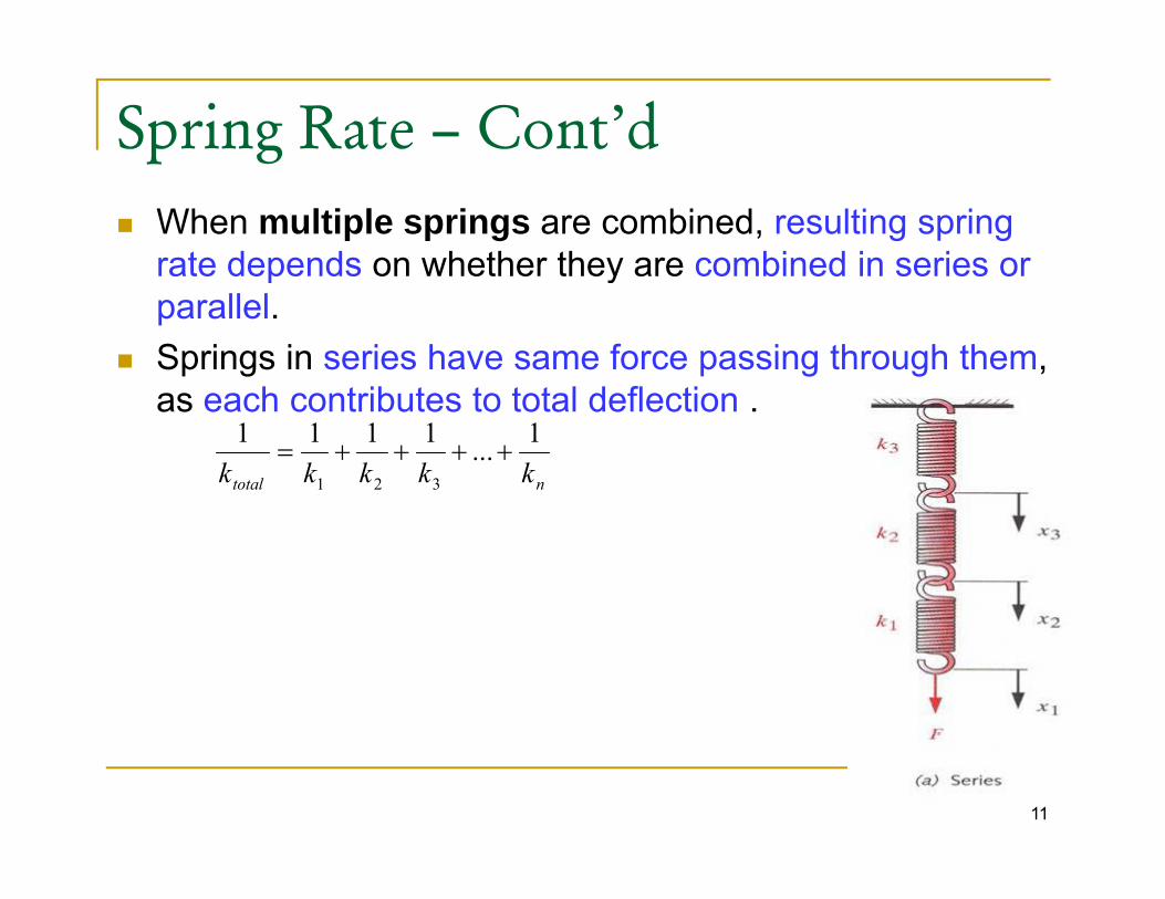
Spring Rate – Cont’dWhen multiple springs are combined, resulting spring rate depends on whether they are combined in series or p yparallel.Springs in series have same force passing through them, as each contrib tes to total deflectionas each contributes to total deflection .
ntotal kkkkk1...1111
321
++++=
11

Spring Rate – Cont’dSprings in parallel have same deflection, and total force is split among them . For springs in parallel, individual p g p g p ,spring rates add directly.
ktotal = k1 + k2 + k3 + …. + kntotal 1 2 3 n
12

10.1 Stresses in Helical Springs
R l T FD/2 d/2AF
JTr
+=maxτA round-wire helical compression spring is loaded by the axial force F.
Replace T = FD/2, r =d/2, J = πd 4/32, A= πd 2/4, τmax=τ :
(10 1)48 FFD (10-1)23
48dF
dFD
ππτ +=
DC.
Define the spring index as:dDC =
For most springs the range for C is: 6 ≤ C ≤ 12 The mean coil diameter DThe wire diameter d.
3
8dFDK S π
τ =
For most springs the range for C is: 6 ≤ C ≤ 12.
13
dπ
CCK S 2
12 += Where KS is a shear-stress correction factor

10.2 The Curvature Effectis based on the wire being straight.
3
8dFDK S π
τ =
In fatigue load: It is important to include the curvature stress.To include the curvature effect, the factor KS needs to be modifiedmodified. The curvature of the wire increases the stress on the inside of the spring but decreases it only slightly on the outside.I i l d h ll b l d bIn static load: these stresses can normally be neglected because it will be relieved by local yielding with first application of a load. CK 615.014 −Wahl factor:
Bergstrasser factor:
CCKW 44
+−
=
24 +CK
14
Bergstrasser factor: 34 −
=C
K B

The curvature correction factor can now be obtained by ycanceling out the effect of the direct shear form KB, thus
( )242 +CCK (10-7)
T di t th l t h t ill th ti
( )( )( )1234
242+−
+==
CCCC
KKK
S
BC
To predict the largest shear stress we will use the equation:
8FD3
8dFDK B π
τ =
1515

10.3 Deflection of Helical Springs
Using the strain energy method to include both the torsionaland shear components, thusp ,
AGlF
GJlTU
22
22
+=
Substituting T = FD/2, l =πDN, J=πd 4/32, A d 2/4 i h i i h
AGGJ 22
A=πd 2/4, in the previous equation we have:
DNFNDFU 2
2
4
32 24+=
Where N=Na=number of active coils
GdGdU 24 +
16
W e e N Na u be o act ve co s

The total deflection y can now be calculated by:FDNNFDU 3 48∂
Since, C = D/d, the deflection y becomes:Gd
FDNGd
NFDFUy 24
48+=
∂∂
=
y
(10-8)Gd
NFDy 4
38≅
The spring rate can be calculated by
Gd
(10-9)ND
GdyFk 3
4
8==
17
y

10.4 Compression Springs
There are four standard types of ends in helical compressionsprings. They are plain end, squared end, plain-ground end,p g y p , q , p g ,and squared-ground end.
18

A spring with plain ends has a noninterrupted helicoids; theends are the same as if a long spring had been cut intosections.sections.
A spring with plain ends that are squared or closed is obtainedby deforming the ends to a zero-degree helix angleby deforming the ends to a zero-degree helix angle.
Springs should always be both squared and ground forimportant applications because a better transfer of the load isimportant applications, because a better transfer of the load isobtained.
A i ith d d d d d b tA spring with squared and ground ends compressed betweenrigid plates can be considered to have fixed ends.
19

The type of end used affects the number of active coils Na and the solid height of the spring.g p g
Square ends effectively decrease the number of total coils Ntby approximately two: Nt = Na+2
•Forys gives an expression for calculating the solid length of y g p g gsquared and ground ends
Ls=(Nt - a)d
Where a varies, with an average of 0.75 which means in this case that the entry dNt in table 10-1 may be overstated.The way to check these variations is to take a spring and count the wire diameters in the solid stack
2020

Table 10-1 shows how the type of end used affects the number of coils and the spring length.
Types of Springs Ends
Term Plain Plain and ground
Squared or Closed
Squared and Ground
End coils, Ne 0 1 2 2e
Total coils, Nt Na Na+1 Na+2 Na+2
Free length, L0 pNa+d p(Na+1) pNa+3d pNa+2d
Solid length, Ls d(Nt+1) dNt d(Nt+1) dNt
Pitch, p (L0-d)/ Na L0/ (Na+1) (L0-3d)/ Na (L0-2d)/ Na
21

Set removal or presetting:
22

Set removal or presetting:
A process used toinduce useful residualstresses.It is done by makingthe spring longer thanthe spring longer thanneeded and thencompressing it to its
lid h i h Lsolid height Ls.
23

This operation sets the spring to the required final free lengthp p g q gL0 and, since the torsional yield strength has been exceeded, itinduces residual stresses opposite in the direction to thoseinduced in serviceinduced in service.Set removal increases the strength of the spring and so isespecially useful when the spring is used for energy-storagepurposes. But, set removal should not be used when springsare subjects to fatigue.
24

10.5 StabilityCompression coil springs may buckle when the deflection becomes too large. The critical deflection is given by the equation:
(10 10)⎥⎤
⎢⎡ ⎞
⎜⎛
2/1'C (10-10)
Where
⎥⎥
⎦⎢⎢
⎣⎟⎠
⎞⎜⎜⎝
⎛−−= 2
2'10 11
effcr
CCLy
λ
Where ycr is the deflection corresponding to the onset of instabilityλeff is the effective slenderness ratio and is given by:
(10-11)α the end condition constant
DL
eff0α
λ =
25

are elastic constants defined by the equations:'2
'1 & CC
( )( )
EGGEC
GEEC
+−
=−
=2
2;2
2'2
'1
π
The end condition constant α depends upon how the ends of the spring are support.
End condition Constant α
Spring s pported bet een flat parallel s rfaces (fi ed ends) 0 5Spring supported between flat parallel surfaces (fixed ends) 0.5
One end supported by flat surface perpendicular to spring axis (fixed); other end pivoted (hinged)
0.707
Both ends pivoted (hinged) 1
One end clamped; other end free 2
26

Absolute stability occurs when the term 2'2 / effC λy
in equation (10-10) is greater than unity. Thus, for stability we have:
2 eff
( ) 2/12 ⎤⎡ GEDπ (10-12)
F t l ti 10 12 b
( )0 2
2⎥⎦⎤
⎢⎣⎡
+−
<EGGEDL
απ
For steels, equation 10-12 becomes:L0 < 2.63D/α
For squared and ground endsFor squared and ground ends α =0.5 and L0 < 5.26D
27

Spring MaterialsLimited number of materials and alloys are suitable for use
ias springs.
Ideal spring material would have high ultimate strength,
high yield point, and low modulus of elasticity in order to
provide maximum energy storage (area under elastic portion p gy g ( p
of stress-strain curve).
F d namicall loaded i fatig e strength propertiesFor dynamically loaded springs, fatigue strength properties
of material are of primary importance.
28

Spring Materials – Cont’dHigh strength and high yield points are attainable from
medium to high carbon and alloy steels and these are mostmedium-to high-carbon and alloy steels, and these are most
common spring materials, despite their high modulus of
elasticity. Few stainless-steel alloys are suitable for springs, as
are beryllium copper and phosphor bronze, among copper
alloys.
Springs are manufactured by hot-or cold-working process. p g y g p
Winding springs induces residual stresses through bending.
These stresses are relieved through mild heat treatmentThese stresses are relieved through mild heat treatment.
29

30

Spring Wire
It is common to use round wire as spring material It isIt is common to use round wire as spring material. It is
available in selection of alloys and wide range of sizes.
Rectangular wire is available only in limited sizes.
31

Tensile StrengthTensile StrengthRelationship between wire size and tensile strength is h b l C ld d d i d i ishown below. Cold-drawn process used in reducing wire
diameter is responsible for hardening and strengthening material at expense of much of its ductility.
32

Tensile Strength
Empirical equation resulting from fitting exponential p q g g pfunction through data for five of materials, is:
AS
Where A and m are defined in Table 10 4 for these
mut dS =
Where A and m are defined in Table 10-4 for these wires materials.
33

34

Shear Strength
A very rough estimate of the torsional yield strength can be y g y gobtained by assuming that the tensile yield strength is between 60 and 90 percent of the tensile strength.
Distortion-energy theory can be applied to obtain torsional
utyut SSS 9.06.0 <<
Distortion-energy theory can be applied to obtain torsionalyield strength: Sys= 0.577Sy. Therefore, for steel:
utysut SSS )9.0(577.0)6.0(577.0 <<
SSS 520350 <<
35
utysut SSS 52.035.0 <<
For wires listed in table 10-5, the maximum allowable shear stress in a spring can be seen in column 3.
Joerres uses the maximum allowable torsional stress for staticJoerres uses the maximum allowable torsional stress for static applications and it is given in table 10-6
Samonov shows that Ssy=τall = 0.56Sut for high-tensile spring steels, which is close to the value given by Joerres for hardened alloy steels.
3636

37

38

ExampleA helical compression spring is made of hard drawn carbon A227 steel has a wire diameter of 0.94 mm. The outside diameter of the spring is 11.11mm. The ends are squared anddiameter of the spring is 11.11mm. The ends are squared and there are 12.5 total turns.
a) Estimate the torsional yield strength of the wire.b) Estimate the static load corresponding to the yield strength.c) Estimate the scale of the spring (the spring constant).d) Estimate the deflection that would be caused by the load in part bd) Estimate the deflection that would be caused by the load in part be) Estimate the solid length of the springf) What length should the spring be to ensure that when it is
compressed solid and then released, there will be no permanent change in the free length?
g) Given the length found in part (f), is buckling a possibility?
39
g) Given the length found in part (f), is buckling a possibility?h) What is the pitch of the body coil?

Solution
a. The torsional yield strength of the wire:y gd = 0.94mmFrom table 10-4, A=1783MPa.mmm and m = 0.19From equation 10-14: Sut = A/dm = 1783/(0.94)0.19 =1804 MPaFrom table 10-6: Ssy = 0.50Sut = 902 MPa
40

b. The static load corresponding to the yield strength:Th i i il di t i D D d 11 11The main spring coil diameter is D = Dout - d = 11.11-0.94=10.17mmThus, the spring index is: C = D /d = 10.17/0.94 = 10.82Thus, the spring index is: C D /d 10.17/0.94 10.82Therefore, from equation 10-3 replacing Ks and τ with KBand Ssy respectively, Thus:
dFDKS Bsy
83==
πτ
CCK
DKSd
F
d
BB
sy 124.13)82.10(42)82.10(4
3424;
8
3
=−+
=−+
==⇒π
π
NFB
734.25)(
=⇒
41
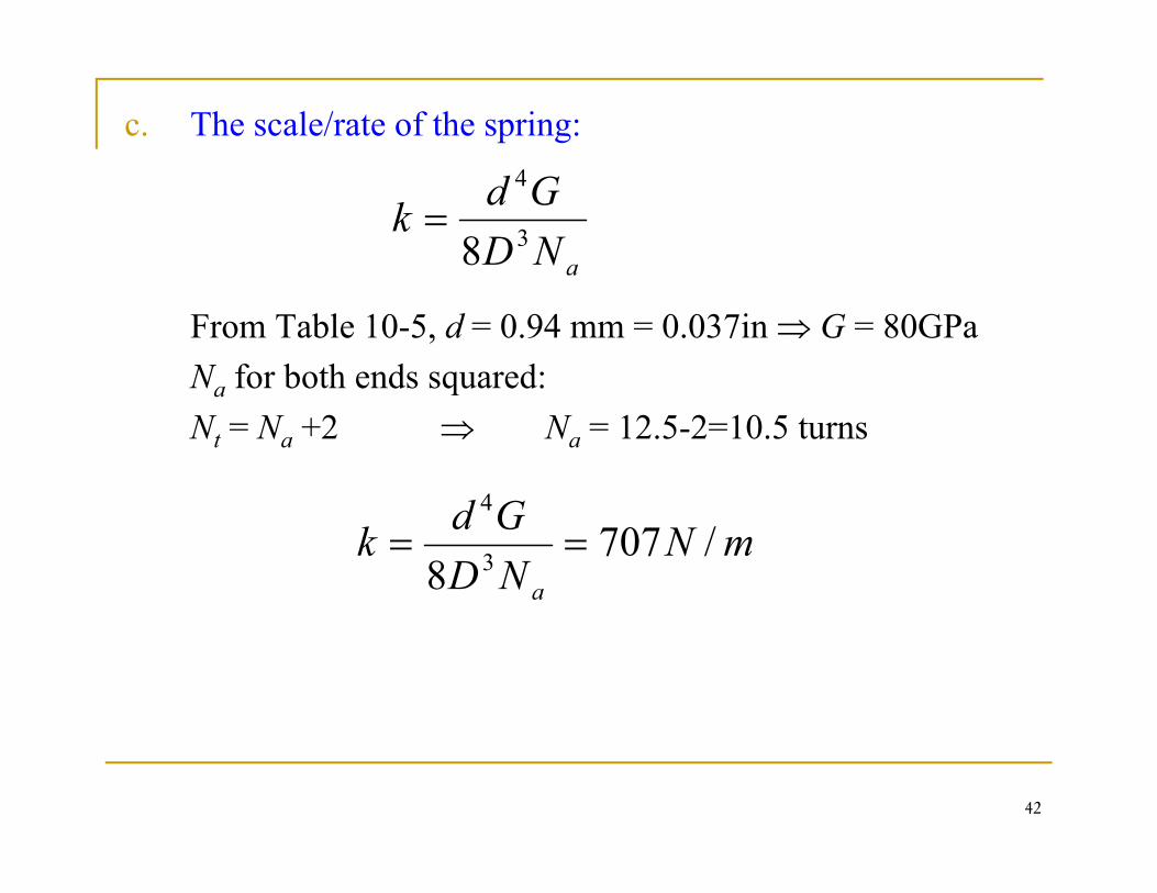
c. The scale/rate of the spring:
aNDGdk 3
4
8=
From Table 10-5, d = 0.94 mm = 0.037in ⇒ G = 80GPaNa for both ends squared: a qNt = Na +2 ⇒ Na = 12.5-2=10.5 turns
Gd 4
mNNDGdk
a
/7078 3
4
==
42

d. The deflection that would be caused by the load in part (b):
mmmFy 43603640734.25====
e The solid length of the spring from table 10-1:
mmmk
y 4.360364.0707
e. The solid length of the spring, from table 10 1:
mmNdL ts 69.12)15.12(94.0)1( =+=+=
f. The free length of the spring suppose to have to be sure when it is compressed and then released, there will be no permanent change in its free length:
mmyLL 094943669120 =+=+=
43
mmyLL s 09.494.3669.120 =+=+=

g. To Check if buckling is possible:For steel and squared ground:For steel and squared ground:
L0 < 5.26D ⇒ L0 < 53.94mm,L0 5.26D ⇒ L0 53.94mm,
since L0 = 49.9mm, therefore: there will be no buckling.
h. The pitch of the body coil is:
( ) ( ) 41.4510
94.0(309.4930 =−
=−
=N
dLp
5.10aN
44

10.7 Helical Compression Spring Design f S i S ifor Static Service
The design of a new spring involves the following considerations:considerations:
Space into which the spring must fit and operateValues of working forces and deflectionsValues of working forces and deflectionsAccuracy and reliability neededTolerances and permissible variations in specificationsEnvironmental conditions such as temperature and presence of a corrosive atmosphereC t d titi d dCost and quantities needed
Designers use these factors to select a material and specify suitable values for wire size, the number of turns, the diameter
45
suitable values for wire size, the number of turns, the diameter and free length, the type of ends, and the spring rate needed to satisfy the working force-deflection requirements.

Some important limits:The range index is:The range index is:
4 ≤ C ≤ 12 (10-18)Lower indexes being more difficult to form (because of theLower indexes being more difficult to form (because of the danger of surface cracking). Higher indexes tending to tangle (knot) often enough to require individual packingindividual packing.
The recommended range of active turns is:g3 ≤ Na ≤ 15 (10-19)
The designer confines (limits) the spring’s operating point to the central 75% of the curve between no load F = 0 and closure (end) F = FS, thus
The maximum operating force SFF87
max ≤
46
p g 8

Maximum Operating Force
47

Defining the fractional overrun to closure as ξ, where(10-17)( )1 FF ξ SF 7 (10 17)( ) max1 FFS ξ+=
1501==≥ξ
SS F
F87
1≤
+ ξ
15.07==≥ξ
The factor of safety at closure (solid height) : ns ≥ 1.2
Figure of merit: The cost of wire from which the spring is wound (coiled)h l i ki h d i i f h i l i d ihelps in making the decision for the optimal spring design.Formula:
(10-22)( )22 DNd
RMCfom tγπ−= ( )
Where RMC is the relative material cost
( )4
RMCfom
48
Where RMC is the relative material cost.

Spring design is an open-ended process with many decisions to be made and many possible solution paths as well asto be made, and many possible solution paths as well as solutions.One possible approach for design spring coil is:
Make a priori decisions, with hard-drawn steel wire the first choice (relative material cost =1)Ch i i dChoose a wire size dgenerate a column of parameters:
d D OD or ID N L L (L ) n and fomd, D, OD or ID, Na, Ls, Lo, (Lo)cr, ns, and fom
By incrementing wire sizes available, a table of parameters y g , pwill be generated. Then, the design recommendation conditions are applied to choose the good design.
49

After wire sizes are eliminated the spring design with theAfter wire sizes are eliminated, the spring design with thehighest figure of merit will be chosen.
This will give the optimal design despite the presence of aThis will give the optimal design despite the presence of adiscrete design variable d and aggregation of equality andinequality constraints.
50

51

52
53

54
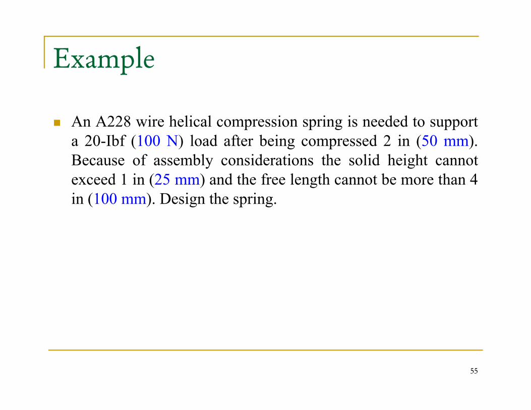
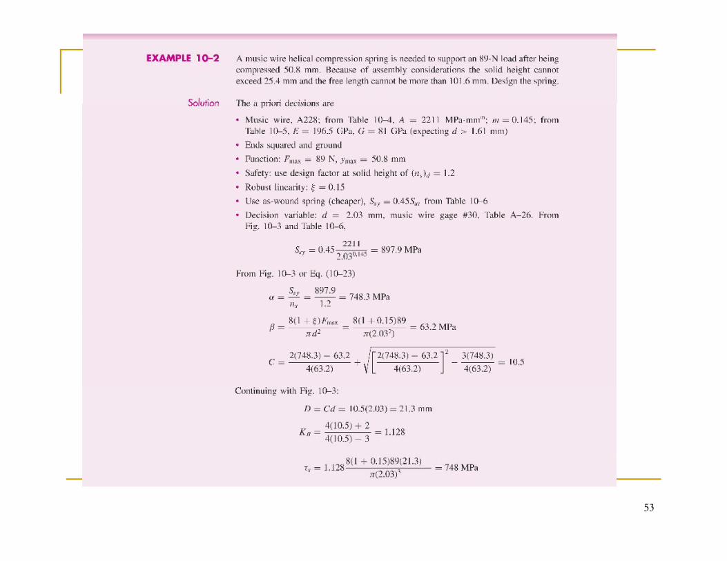
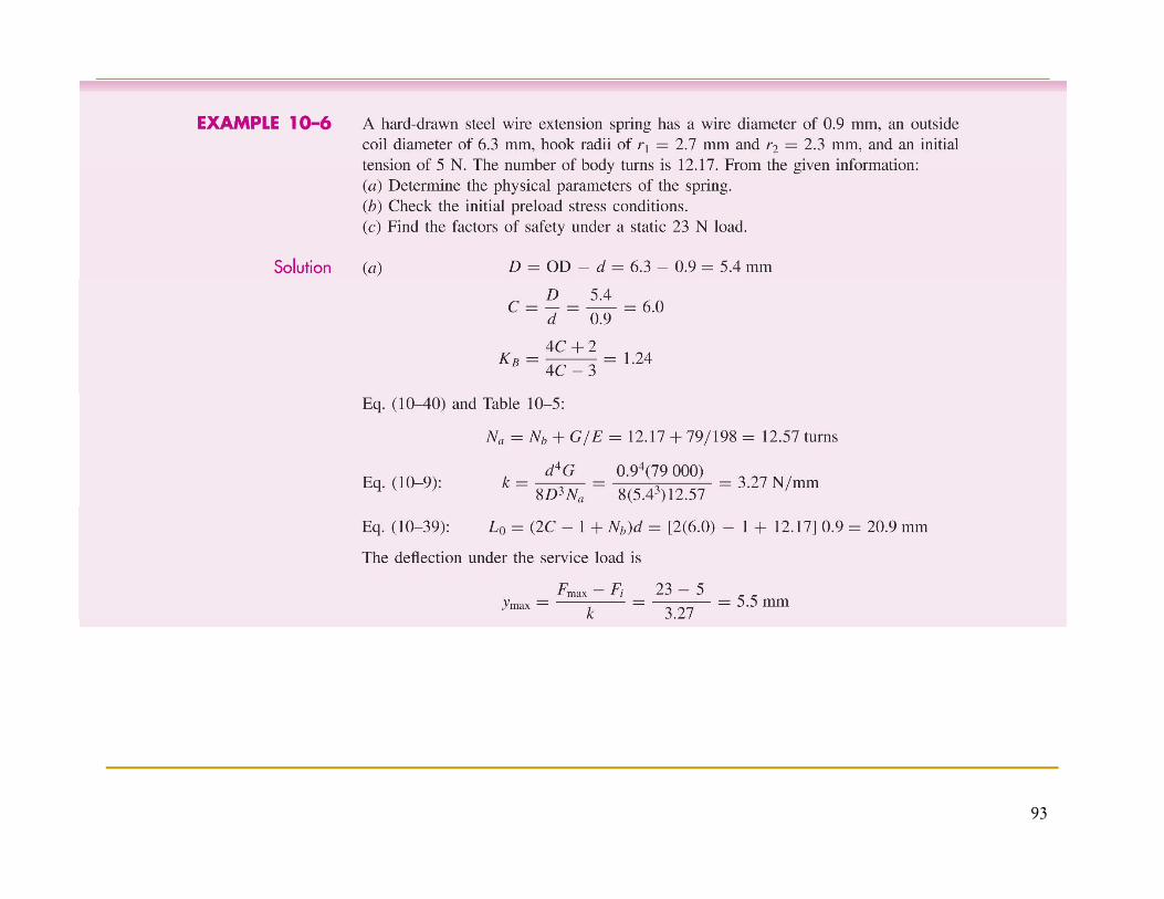
Example
An A228 wire helical compression spring is needed to supportp p g ppa 20-Ibf (100 N) load after being compressed 2 in (50 mm).Because of assembly considerations the solid height cannotexceed 1 in (25 mm) and the free length cannot be more than 4exceed 1 in (25 mm) and the free length cannot be more than 4in (100 mm). Design the spring.
55

Solution
For A228 wire helical spring: From Table, A=201 kpsi-inm and 0 145m=0.145
From Table 10-5, E = 28.5Mpsi, G =11.75Mpsi (choosing d > 0.064 in)Ends squared and groundFunction: Fmax= 20 Ibf, ymax= 2 inSafety: use design factor at solid height of (ns)d =1.2Sa ety: use des g acto at so d e g t o (ns)d .Select robust linearity: ξ = 0.15Use as wound spring, Ssy= 0.45Sut from table 10-6
56

Decision variable: d =0.08 in, from figure 10-3 and table 10-6:, g
46.13045.0 == kpsidAS msy
713.108==α kpsinS
d
s
sy
( )15.9
182
max =+
=πξ
β kpsid
F
53.1043
42
42
2/12
=⎟⎟
⎠
⎞
⎜⎜
⎝
⎛−⎟⎟
⎠
⎞⎜⎜⎝
⎛ −+
−=
βα
ββα
ββαC
5757
⎠⎝
8424.0== CdD
7.108)/()1(8
128.1)34/()24(3
max =+=
=−+=
kpsidDFK
CCK
Bs
B
πξτ
923.0
2.1/
=+=
==
indDOD
Sn ssys τ
05.12205.1005.10)8/( max
3max
4
=+===
turnsNturnsFDyGdN
t
a
264.3)1(964.0
max =++=+===
inyLyLLindNL
ssso
ts
ξ( )
417.04/6.2
43.4/63.222
max
−=−=
==
DNdfom
inDL
t
cro
ssso
π
α
58
7.0/6. Ndfom tπ

Repeat the above analysis for other diameters and form a table p yto select the best spring design:
d 0.063 0.067 0.071 0.075 0.08 0.085 0.09 0.095
D 0.391 0.479 0.578 0.688 0.843 1.017 1.211 1.427
C 6.205 7.153 8.143 9.178 10.53 11.96 13.46 15.02
OD 0.454 0.546 0.649 0.763 0.923 1.102 1.301 1.522
Na 39.1 26.9 19.3 14.2 10.1 7.3 5.4 4.1
Ls 2.587 1.936 1.513 1.219 0.964 0.790 0.668 0.581
Lo 4.887 4.236 3.813 3.519 3.264 3.090 2.968 2.881
(Lo)cr 2.06 2.52 3.04 3.62 4.43 5.35 6.37 7.51
ns 1.2 1.2 1.2 1.2 1.2 1.2 1.2 1.2
fom -0.409 -0.399 -0.398 -0.404 -0.417 -0.438 -0.467 -0.505
59

Examine the table and perform the adequacy assessment.The constraint 3≤ Na ≤ 15 cancel wire diameters less than 0.08 inTh t i t 4≤ C ≤ 12 l di t l th 0 085 iThe constraint 4≤ C ≤ 12 cancel diameters larger than 0.085 in.The constraint Ls < 1 in cancel diameters less than 0.080 inThe constraint Lo < 4 in cancel diameters less than 0.071 inThe buckling criterion cancel free length longer than (L ) which cancelThe buckling criterion cancel free length longer than (Lo)cr, which cancel diameters less than0.075in.The result is that there are only two springs in the feasible domain.The figure of merit decides that the wire diameter is 0.08 in.
d 0.063 0.067 0.071 0.075 0.08 0.085 0.09 0.095
D 0.391 0.479 0.578 0.688 0.843 1.017 1.211 1.427
C 6 205 7 153 8 143 9 178 10 53 11 96 13 46 15 02C 6.205 7.153 8.143 9.178 10.53 11.96 13.46 15.02
OD 0.454 0.546 0.649 0.763 0.923 1.102 1.301 1.522
Na 39.1 26.9 19.3 14.2 10.1 7.3 5.4 4.1
Ls 2.587 1.936 1.513 1.219 0.964 0.790 0.668 0.581
Lo 4.887 4.236 3.813 3.519 3.264 3.090 2.968 2.881
(Lo)cr 2.06 2.52 3.04 3.62 4.43 5.35 6.37 7.51
ns 1.2 1.2 1.2 1.2 1.2 1.2 1.2 1.2
fom -0.409 -0.399 -0.398 -0.404 -0.417 -0.438 -0.467 -0.505
60

10.8 Critical Frequency of Helical SpringsThe natural frequency of the spring should not be close to thefrequency of the applied force; otherwise resonance mayoccur, resulting in damaging stresses.
The governing equation for the translational vibration of a g g qspring is the wave equation:
(10-24)2
2
22
2 uWu ∂=
∂
Wherek i t l ti d t it
222 tkglx ∂∂
k = spring rate ; g = acceleration due to gravityl = length of spring; W= weight of springx = coordinate along length of spring
61
x coordinate along length of springu = motion of any particle at distance x

Equation (10-24) has a harmonic solution and it depends on: Given physical propertiesGiven physical propertiesEnd conditions of the spring
The natural frequencies for a spring placed between two flat and parallel plates:
,...3,2,1== nWkgnπω
Since ω = 2πf, thus
W
,...3,2,11== nkgfSince ω 2πf, thus ,,,
2 Wf
If n =1, it is called the fundamental frequency and it is equal to:
(10-25)Wkgf
21
=
62

For spring that has one end against a flat plate and other endFor spring that has one end against a flat plate and other end free, the frequency is
(10-26)kgf 1=
W can be calculated as:
Wf
4
Where γ is the specific weight ( weight per unit volume)
( ) γπγππγ aa DNdDNdALW 222
41
4===
Where γ is the specific weight ( weight per unit volume)
To avoid resonance with the harmonic it is required that the fundamental critical frequency is 15~20 ≥ the frequency of thefundamental critical frequency is 15 20 ≥ the frequency of the force or motion of the spring.
20≥ff
63
opf

10.9 Fatigue Loading of Helical C i S iCompression Springs
Helical springs are never used as both compression andp g pextension springs. This is because they are usually assembledwith a preload so that the working load is additional. Thus, thespring application fall under the condition of fluctuatingspring application fall under the condition of fluctuatingloads.Thus,
aFF
F−
= minmax
2
am FFFF
F +=+
= minminmax
2
2
64

Therefore, the amplitude and midrange shear stresses respectively can be written as:respectively can be written as:
33
8;8d
DFKd
DFK mBm
aBa π
τπ
τ ==
Endurance limits for infinite life were found to be for unpeenedd d i (T i l d h )
dd ππ
and peened springs (Torsional endurance strength components)Unpeened: Ssa= 35.0 kpsi (241MPa) Ssm= 55.0kpsi (379MPa)Peened: S = 57.5 kpsi (398MPa) S = 77.5kpsi (534MPa)Peened: Ssa 57.5 kpsi (398MPa) Ssm 77.5kpsi (534MPa)
Then Sse can be calculated using Goodman theory: Torsional endurance strength : S
where Ssu=0.67Sut (Ssu is the ultimate torsional strength)( )susm
sase SS
SS
/1−=
65

66

67

68

69

Example
A helical compression spring, made of A228 wire, has a wirep p g, ,size of 0.092 in (2.3 mm), an outside diameter of 0.5625 in(14.6 mm), a free length of 4.125 in (35.9 mm), 21 activecoils and both ends squared and ground The spring is to becoils, and both ends squared and ground. The spring is to beassembled with a preload of 5 lb (22.27 N) and will operateto a maximum load of 35 lb (160 N) during use. Knowingthat the spring is unpeened type.
1. Find the factor of safety guarding against a fatigue failure.2 Find the critical operating frequency2. Find the critical operating frequency
70

SolutionGiven OD = 0.5625 in, d = 0.092 in, Na = 21A228 spring type material, G = 11.75 GpsiFmax= 35 lb, Fmin= 5 lbBoth ends squared and ground, and unpeened.
Th f i f f f1. The fatigue factor of safety:
dDCindODD 11.5/;4705.0 ===−=
( ) ( ) lbFlbFCCK
ma
B
202/535;152/535287.1)34/()24(
=+==−==−+=
( ) ( )
kpsid
DFKkpsid
DFK mBm
aBa
ma
8.338;7.29833 ====
πτ
πτ
71

From table 10-4, A = 201 kpsi-inm, m = 0.145, therefore
kpsiSS
kpsidAS mut
347190670
1.284==
For unpeened spring:
kpsiSS utsu 347.19067.0 ==
kpsiS
S
kpsiSkpsiS
sa
smsa
2249
5535
==
==
( ) kpsiSS
Ssusm
se 22.49/1
=−
=
The factor of safety guarding against failure to be
28.11=
+=⇒=+
semsua
susef
fsu
m
se
a
SSSS
nnSS ττ
ττ
72

2. The critical frequency:
inlbNDGdk
a
/1.488 3
4
==
lbfW
inlbDNdW a
05860
/284.0;41 322
=∴
== γγπ
HzWkgf
lbfW
281586.0
)386(1.4821
21
0586.0
===
=∴
Check for operating frequency: For good design g g
1.1420
20 ≤⇒≤⇒≥ opopop
fffff
73
opf

10.10 Helical Compression Spring Design f i difor Fatigue Loading
ExamplepA helical compression spring, made of A228 wire, withinfinite life is needed to resist a dynamic load that varies from5 t 20 lbf t 5 H hil th d d fl ti i f 0 5 t 25 to 20 lbf at 5 Hz while the end deflection varies from 0.5 to 2in. Because of assembly considerations, the solid height cannotexceed 1.2 in and the free length cannot be more than 4 in. Thespringmaker has the following wire sizes in stock: 0.069,0.071, 0.080, 0.085, 0.090, 0.095, 0.105, and 0.112 in.
74

SolutionFrom table 10-4 for A228: A=201 kpsi.inm, m = 0.145, G =11.75Mpsi, relative cost of wire = 2.6Surface treatment: unpeendedEnd treatment: squared and groundEnd treatment: squared and groundSelect robust linearity: ξ = 0.15 and fop = 5HzFatigue safety: nf =1.5 using the Sines-Zimmerli fatigue-failure criterioncriterionUse as wound spring, Ssy= 0.45Sut from table 10-6Fmin= 5lbf, Fmax= 20lbf, ymin= 0.5 in, ymax= 2 in, spring operates free ( no rod or hole)operates free ( no rod or hole)Decision variable: wire size dThe design strategy will be to set wire size d, build a table, inspect the table, and choose the satisfactory spring with the highest figure of merit.
75

Replace Ssy by Sse ,ns by nf and (1+ξ)F by F(1+ξ)Fmax by Fa
nf =Ssa/ τa
76

Design analysis based on d = 0.112 in
lbf5.12520lbf5.7520=
+==
−= FF
lbf/in1020
lbf5.122
lbf5.72
max ===
ma
Fk
FF
kpsi1.2762012
1450
max
==utS
y
k i2124450kpsi0.18567.0
p112.0 145.0
== utsu
ut
SSSS
kpsi2.12445.0 == utsy SS
77

For Unpeened spring, from equation (10-28): Ssa= 35.0 kpsip p g, q ( ) sa pSsm= 55.0kpsi
In Sines failure criterion, the terms Ssm is ignored, thus
( ) kpsi3501
35/1
=−
=−
=susm
sase SS
SS ( )susm
78

T fi d C l S b S b d (1 ξ)F b FTo find C, we replace Ssy by Sse , ns by nf , and (1+ξ)Fmax by Fa, thus:
kpsi333.23== se
nS
α
kpsi523.18
2 == a
f
dF
n
πβ
005.1443
42
42
2/12
=⎟
⎠
⎞
⎜⎜
⎝
⎛−⎟⎟
⎠
⎞⎜⎜⎝
⎛ −+
−=C
d
βα
ββα
ββα
π
( ) lbf231in569.1
444
ma =+===
⎠⎜⎝ ⎠⎝
FFCdD
ξ
βββ
( )
turns98.7298.5turns98.5)8/(
lbf23134
max
=+===
+
t
a
s
NkDGdN
FF ξ
79
t

( ) i1943/in894.0==
kFLLLdNL ts
( )
i6811in457.1
in194.3/=−=
=+=+=
dDODdDID
kFLyLL sssso
( ) in2538/632in3.2
in681.1=−==+=
DLLLydDOD
sos
α( )
lbf0825.04
in253.8/63.222
==
==
DNdW
DL
a
cro
γπ
α
Hz1083865.0
4
==W
kfn
80
W

8094.1)34/()24( =−+=
DFCCK B
8
kpsi334.238
3 ==
DFd
DFK a
Ba πτ
k i56718
kpsi89.388
3 ==
DFK
dDF
K
s
mBm π
τ
5.1/
kpsi56.713
==
==
Snd
K
asaf
sBs
τπ
τ
01.14/6.2
74.1/22 −=−=
==
DNdfom
Sn
t
ssys
π
τ
81
f t

Repeat the above analysis for other wire di d f bl l h b diameters and form a table to select the best spring design:
Knowing that we have two types of constrainsg ypGeneral Constraints:The constraint 3 ≤ Na ≤ 15 cancel wire diameters less than 0 105 in0.105 inThe constraint 4≤ C ≤ 12 cancel diameters larger than 0.105 in.Problem Constraints:The constraint Ls ≤ 1.2 in cancel diameters less than 0.1050 inThe constraint Lo ≤ 4 in cancel diameters less than 0.095 inf ≥ 20f f ≥ 100H l di t l th 0 090 ifn ≥ 20fop ⇒ fn ≥ 100Hz cancel diameters less than 0.090 inThe buckling criterion cancel free length longer than (Lo)cr, which cancel diameters less than0.075in.
82

Repeat the above analysis for other wire di d f bl l h b diameters and form a table to select the best spring design:
d 0.069 0.071 0.080 0.085 0.090 0.095 0.105 0.112
D 0.297 0.332 0.512 0.632 0.767 0.919 1.274 1.569
ID 0.228 0.261 0.432 0.547 0.677 0.824 1.169 1.457
OD 0.366 0.403 0.592 0.717 0.857 1.014 1.379 1.681
C 4.33 4.67 6.40 7.44 8.53 9.67 12.14 14.00
Na 127.2 102.4 44.8 30.5 21.3 15.4 8.63 6.0
L 8 916 7 414 3 74 2 75 2 10 1 655 1 116 0 895Ls 8.916 7.414 3.74 2.75 2.10 1.655 1.116 0.895
Lo 11.216 9.714 6.040 5.05 4.40 3.955 3.416 3.195
(Lo)cr 1.562 1.744 2.964 3.325 4.036 4.833 6.703 8.25
n 1 50 1 50 1 50 1 50 1 50 1 50 1 50 1 50nf 1.50 1.50 1.50 1.50 1.50 1.50 1.50 1.50
ns 1.86 1.85 1.82 1.81 1.79 1.78 1.75 1.74
fn 87.5 89.7 96.9 99.7 101.9 103.8 106.6 108
83
fom -1.17 -1.12 -0.983 -0.948 -0.930 -0.927 -0.958 -1.01

10.11 Extension Springs
Most of the preceding discussion of compression springs applied equally to helical extension springsapplied equally to helical extension springsThe natural frequency of a helical extension spring with both ends fixed against axial deflection is the same as that for a helical spring in compressionhelical spring in compressionHowever:
In extension spring, the coils are usually close wound so that there is an initial tension or so termed preload F. Therefore, no deflection occurs until the initial tension built into the spring is overcome. That is: the applied load F becomes larger than initial t i (F > F )tension (F > Fi)The load transfer can be done with: a threaded plug or a swivel hook
84

Types of ends used on extension springs
85

In designing a spring with a hook end, ,bending and torsion in the hook must be included in theincluded in the analysis.The figure shows two common used method of designing the end. c and d show anc and d show an improved design due to a reduced coil
86
diameter.

The maximum tensile stress at A, due to bending and axial loading, is given g g, gby:
( ) ⎥⎤
⎢⎡ +=
416DKFσ
Where (K)A is a bending stress
( ) ⎥⎦⎢⎣+= 23 dd
KF AA ππσ
Where (K)A is a bending stress correction factor for curvature, given by:
CC 2 214( ) ( ) drC
CCCCK A
11
11
12
1 214
14=
−−−
=
87

The maximum torsional stress at point B is given by:point B is given by:
( ) 8FDKτ = ( ) 3dK BB π
τ =
Where (K)B is the stress correction factor for curvature and it is givenfactor for curvature and it is given by:
( ) rC
CK 22 214 −( )
dC
CK B
22
2
2
44=
−=
88

If coils in contact with one another, the springs is known as close-If coils in contact with one another, the springs is known as closewound.The load-deflection relation can be written as:
F=F + kyF=Fi + kyWhere k is the spring rate
Th f l th L f i d i id th d lThe free length Lo of a spring measured inside the end loops or hooks can be expressed as Lo= 2(D-d) + (Nb+1)d = (2C-1+Nb)d
89
o ( ) ( b ) ( b)D mean coil diameter; Nb number of body coils; C the spring index

The equivalent number of active helical turns Na for the spring rate k is:spring rate k is:Na = Nb + G/EWhere G and E are the shear the tensile modulus of elasticityThe amount of initial tensionThe amount of initial tension that a springmaker can routinely incorporate is as shown in the figure c
90

The preferred range can be expressed in terms of the uncorrectedThe preferred range can be expressed in terms of the uncorrected torsional stress τi as:
C ⎞⎛ 333500(10-41)( ) psiC
Ci ⎟⎠⎞
⎜⎝⎛ −
−±=5.6341000
105.0exp33500τ
The maximum allowable corrected stresses (i.e.; using KW or KB) for static applications of extension springs are given in table 10-710 7
Percent of Tensile StrengthIn Torsion In Bending
Materials body end end
Patented, cold-drawn or hardened and tempered carbon and low-alloy steels
45-50 40 75
91
Austenitic stainless steel and nonferrous alloys 35 30 55

92
93

94

95

96

97

98

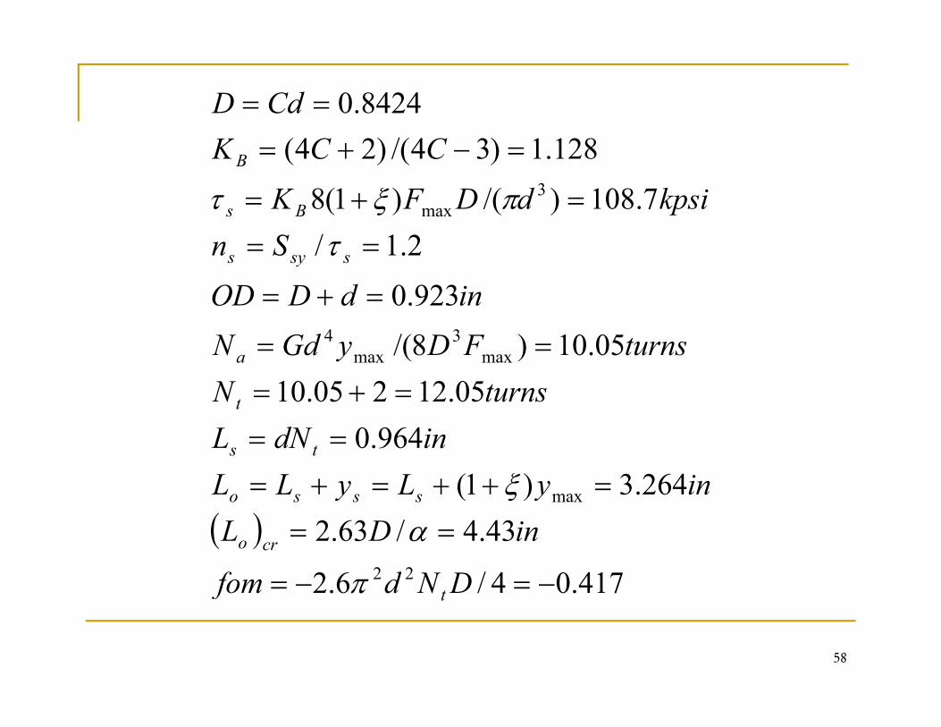
Example
A hard drawn steel wire extension spring has a wire diameterp gof 0.035 in, an outside coil diameter of 0.248 in, hook radii ofr1= 0.106 in and r2 = 0.089in, and an initial tension of 1.19 lbf.The number of body turns is 12 17 From the givenThe number of body turns is 12.17. From the giveninformation:
Determine the physical parameters of the spring (D, C, KB,BNa, k, Lo, ymax)Check the initial preload stress conditionsFi d h f f f d i 5 25 lbf l dFind the factors of safety under a static 5.25 lbf load.
99

Solutiond = 0.035 in, OD = 0.248 in, r1= 0.106 in, r2 = 0.089 in, Nb = 12.17; Fi = 1.19 lbf, Fmax=5.25HD steel ⇒ Form table 10 5 with 0 033 < d < 0 063 ⇒ E =HD steel ⇒ Form table 10-5, with 0.033 < d < 0.063 ⇒ E = 28.7Mpsi, G=11.6MpsiFrom table 10-4, A =140kpsi-inm, m = 0.19The physical parameters
213.0035.0248.0 =−=−= dODD
turns5712728/6111712/
234.13424;086.6/
=+=+=
=−+
===
EGNNCCKdDC B
lbf/in76.178
turns57.127.28/6.1117.12/
3
4
==
=+=+=
NDGdk
EGNN ba
100( ) in817.012
8=+−= dNCL
ND
bo
a
The deflection under the service load is:
( )in229.0
76.1719.125.5max
max =−
=−
=k
FFy i
Therefore the maximum spring length is:
L = Lo + ymax =0.817 + 0.229 = 1.046 in
101

Initial preload stress condition:The uncorrected initial stress is given by equation (10-3) without the correction factor:
( ) kpsi1.158
3 ==d
DFiuncorri π
τ
The preferred range is given by equation (10-41):
( ) k i221k i21435251768134100033500 C±⎞
⎜⎛ −
±( ) ( ) kpsi2.21kpsi2.143525176815.6
41000105.0exp
orCprefi =±=
⎠⎞
⎜⎝⎛ −±=τ
Thus, the initial tension of 15.1 kpsi is in the preferred range.
102

The factor of safety under static loadWe need to check three positions:
The shear stress under the service loadTh b di t th d h k hi h i t d b i t AThe bending at the end hook which is represented by point AThe torsion at the end hook which is represented by point B
F th h t d th i l d1. For the shear stress under the service load8
&45.0; 3max
max ===d
DFKSS
Sn Butsy
sy
πτ
τ
kpsi7.264035.0140
19.0
max
===dAS
d
mut
πτ
( )( )7264450
kpsi82035.0
)213.0)(25.5(8234.1 3max ==π
τ
103
( ) 45.182
7.26445.0==n

2. The bending at the end hook which is represented by point A
( )
14416
kpsi5.1987.26475.075.0;
2 −−⎤⎡
==== utyA
yA
CCD
SSS
nσ
( ) ( ) ( )( ) kpsi9.15614.1
057.6/214
14;416
1111
1123max
=⇒=
==−−−
=⎥⎦⎤
⎢⎣⎡ +=
AA
AAA
K
drCCC
CCK
ddDKF
σππ
σ
27.19.1565.198==An
104

Th i h d h k hi h i d b i B3. The torsion at the end hook which is represented by point B
( ) k i8810572644040sy SSS ( )
( ) ( ) 086.5/214;8
kpsi88.1057.2644.04.0;
222
3max ==
−==
====
BBB
utsyB
yB
drCCCK
dDF
K
SSn
τ
τ
( ) ( )
( )88105
kpsi4.7818.144
; 222
3
=⇒=−
BB
BBB
KCd
τπ
Note that S =0 4 Sut from table 10-7 under torsion for the end part
35.14.7888.105
==Bn
Note that Ssy 0.4 Sut from table 10 7 under torsion for the end part.
From all three calculations, the yield will first occur due to the bending of the end hook.
105

Fatigue Example
The helical extension spring of the pervious example isp g p psubjected to a dynamic loading from 1.5 lbf to 5 lbf. Estimatethe factors of safety using Goodman failure criterion for
Th il f ti f th b d iThe nf coil fatigue for the body springThe ny coil yield for the body springThe (n ) end hook bending fatigue at point AThe (nf )A end hook bending fatigue at point AThe (nf )B end hook torsion fatigue at point B
106

Solutiond = 0.035 in, D = 0.213 in, r1= 0.106 in, r2 = 0.089 in, Nb = 12.17Fi = 1.19 lbf, Fmin=1.5, Fmax=5Fi 1.19 lbf, Fmin 1.5, Fmax 5
From the pervious example we have:C=6.086, Lo=0.817, k = 17.76 lbf/inKB=1.234, (K)A=1.14, (K)B=1.18, (τi)uncorr = 15.1 kpsiS = 264 7kpsi S = 0 67S = 177 3 kpsi S =198 5 kpsi SSut 264.7kpsi, Ssu 0.67Sut 177.3 kpsi, Sy 198.5 kpsi, Ssy=119.1 kpsi (shear in body)
107

The fatigue in the body coil:
( ) ( )( ) ( )
kpsi7.508kpsi,3.278lbf25.32/5.15lbf,75.12/5.15
33 ====
=+==−=DFKDFK
FF
mB
aB
ma
ττ kpsi7.50kpsi,3.27 33 dK
dK BmBa π
τπ
τ
For unpeened spring:k i55k i35 SS
( ) kpsi74.50/1
kpsi55kpsi35
=−
=
==
sase
smsa
SSSS
SS
The factor of safety guarding against failure to be
( )/1− susm SS
214.11=
+=⇒=+ suse
fma
SSSS
nnSS ττ
ττ
108
+ semsuafsuse SSnSS ττ

Th il i ldThe coil yield
say
Sn
τ=
To find the values of Ssa:The load line: Ssy
aτ
e o d e:(1)
Ssa
r
im
arττ
τ−
=
SS(2)
SsySsmτi
1=+sy
sm
sy
sa
SS
SS
The intersection between 1 & 2 gives: ( )isysa S
rrS τ−+
=1
109
r +1

Therefore:
kpsi6.183.2775119.1
=⎟⎠⎞
⎜⎝⎛=⎟⎟
⎠
⎞⎜⎜⎝
⎛=⇒= a
ii
ai
FF
FFττ
ττ
85.06.187.50
3.2775.1
=−
=
⎠⎝⎠⎝ aai
r
FFF
:kpsi2.46=sa
ThusS
69.13.272.46==yn
110

The end hook bending fatigue at point Ag g p
( )416
;///1
⎤⎡
+= utmeaf
D
SSn σσ
( )
k i197
;kpsi3.5241623
⎞⎜⎜⎛
=⎥⎦⎤
⎢⎣⎡ +=
m
Aaa
Fdd
DKFππ
σ
kpsi1.67
kpsi1.97
==
=⎠
⎜⎜⎝
=
see
aa
mm
SS
Fσσ
( ) 87.0
p577.0=⇒
Af
e
n
111

The end hook torsion fatigue at point Bg p
( )///1 += susmsesaf SSn ττ
( ) ( )
8
kpsi1.268
3 == aBBa
DFd
DFK
πτ
( ) ( )
( ) 271
kpsi5.488
3
=⇒
== mBBm
nd
DFK
πτ
( ) 27.1=⇒Bfn
112

Given A229 (OQ&T spring steel) squared and ground-Given A229 (OQ&T spring steel), squared and groundended helical compression spring, d = 3.4 mm, OD = 50.8 mm, Lo = 74,6 mm, Nt = 5.25.I th i lid f ? If t h t i th l t fIs the spring solid safe? If not, what is the largest free length to which it can be wound using ns = 1.2?
113

Τs < Ssyy
Τs = KB ( 8 Fs D/(π d3)
Fs = k ys
114

115

116