lecture 9 ultimate strength of ship hulls - snuocw.snu.ac.kr/sites/default/files/note/lecture...
TRANSCRIPT

OPen INteractive Structural Lab
Topics in Ship Structural Design(Hull Buckling and Ultimate Strength)
Lecture 9 Ultimate Strength of Ship Hulls
Reference : CSR Rule
Ultimate Limit State Design of Steel-Plated Structures Ch. 8
Ultimate Limit State Design of Ship Structures Ph.D Thesis of B.J. Kim
NAOE
Jang, Beom Seon

OPen INteractive Structural Lab
1. General
Hull girder bending moment capacity
The hull girder ultimate bending moment capacity, MU, : the maximum
sagging bending capacity of the hull girder beyond which the hull will
collapse.
Hull girder failure is controlled by buckling, ultimate strength and yielding of
longitudinal structural elements.
The maximum value on the static non-linear bending moment-curvature
relationship M-κ. The curve represents the progressive collapse behavior of
hull girder under vertical bending.
2
CSR
Bending Moment - Curvature Curve M-κ
OPen INteractive Structural Lab
1. General
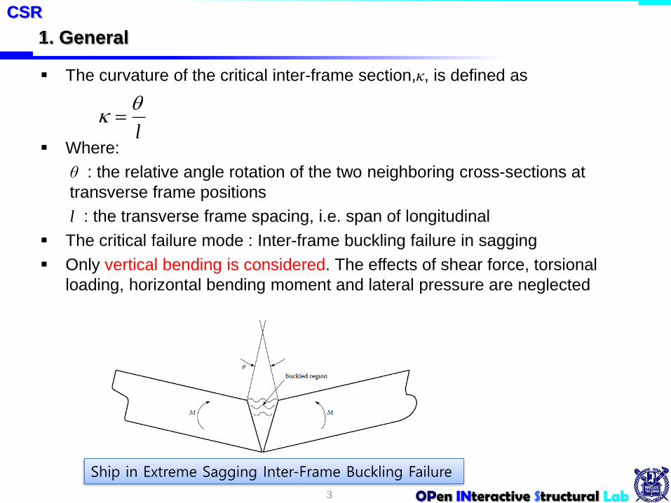
The curvature of the critical inter-frame section,κ, is defined as
Where:
θ : the relative angle rotation of the two neighboring cross-sections at
transverse frame positions
l : the transverse frame spacing, i.e. span of longitudinal
The critical failure mode : Inter-frame buckling failure in sagging
Only vertical bending is considered. The effects of shear force, torsional
loading, horizontal bending moment and lateral pressure are neglected
3
CSR
l
Ship in Extreme Sagging Inter-Frame Buckling Failure
OPen INteractive Structural Lab
2. Single Step Ultimate Capacity Method
4
CSR
σU
σBot
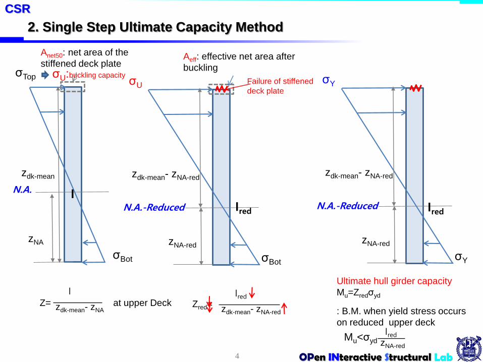
Aeff: effective net area after
buckling
Failure of stiffened
deck plate
N.A.-Reduced
zNA-red
Ired
zdk-mean- zNA-red
Ired
zdk-mean- zNA-redZred=
σTop
σBot
Anet50: net area of the
stiffened deck plate
N.A.
zNA
zdk-mean
I
I
zdk-mean- zNAZ= at upper Deck
σU:buckling capacity
Ultimate hull girder capacity
Mu=Zredσyd
: B.M. when yield stress occurs
on reduced upper deck
σY
σY
N.A.-Reduced
zNA-red
Ired
zdk-mean- zNA-red
Ired
zNA-red
Mu<σyd
OPen INteractive Structural Lab
2. Single Step Ultimate Capacity Method
5
CSR – Calculation of hull girder ultimate capacity
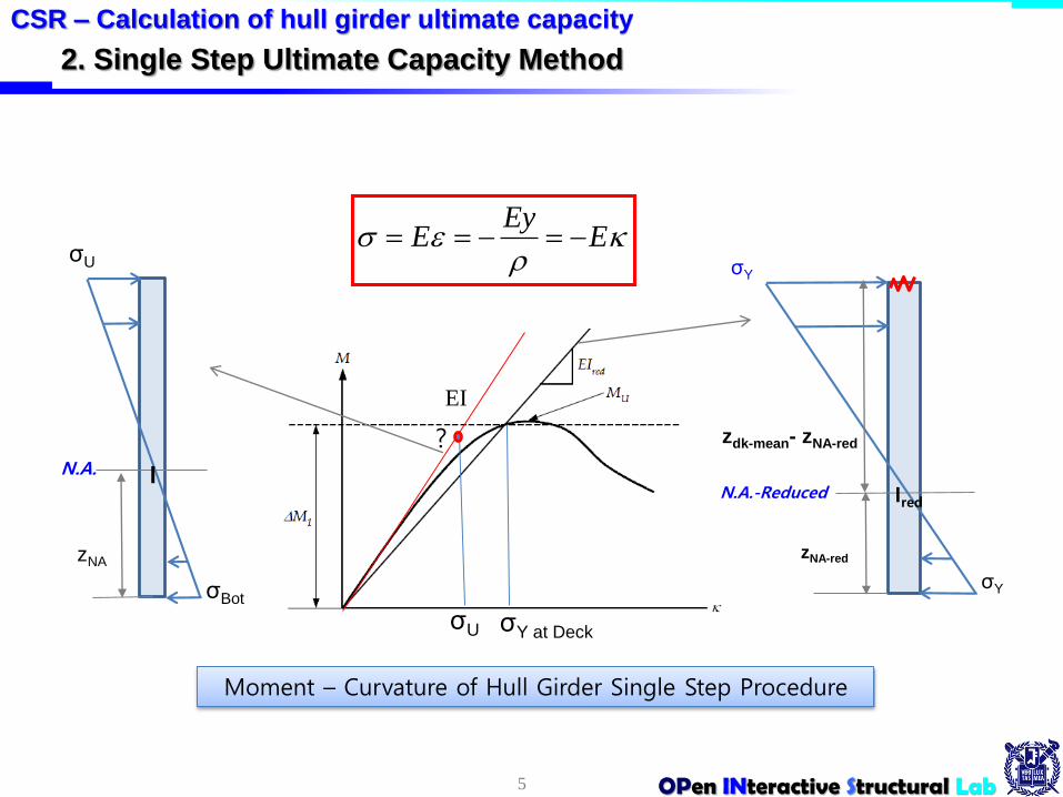
Moment – Curvature of Hull Girder Single Step Procedure
σY
σY
N.A.-Reduced
zNA-red
Ired
zdk-mean- zNA-red
EEy
E σU
σBot
N.A.
zNA
I
EI
σY at DeckσU
?

OPen INteractive Structural Lab
2. Single Step Ultimate Capacity Method
Single Step Ultimate Capacity Method
The assumption : that the ultimate sagging capacity of tankers is the point at
which the ultimate capacity of the stiffened deck panels is reached
The single step procedure for calculation of the sagging hull girder ultimate
bending capacity is a simplified method based on a reduced hull girder
bending stiffness accounting for buckling of the deck
MU = Zredσyd ⋅103 kNm
Zred : reduced section modulus of deck
Ired : reduced hull girder moment of inertia using
• a hull girder net thickness of tnet50 for all longitudinally
• effective members the effective net area after buckling of each stiffened panel of
the deck, Aeff.
6
CSR
3mzz
IZ
redNAmeandk
redred
OPen INteractive Structural Lab
2. Single Step Ultimate Capacity Method
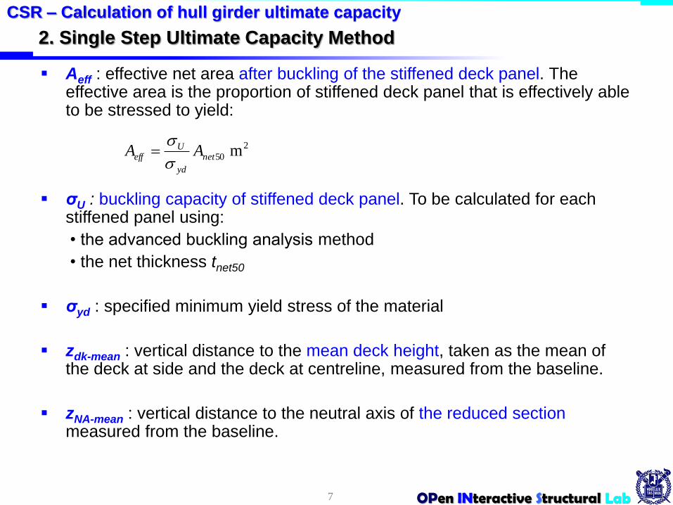
Aeff : effective net area after buckling of the stiffened deck panel. The effective area is the proportion of stiffened deck panel that is effectively able to be stressed to yield:
σU : buckling capacity of stiffened deck panel. To be calculated for each stiffened panel using:
• the advanced buckling analysis method
• the net thickness tnet50
σyd : specified minimum yield stress of the material
zdk-mean : vertical distance to the mean deck height, taken as the mean of the deck at side and the deck at centreline, measured from the baseline.
zNA-mean : vertical distance to the neutral axis of the reduced section measured from the baseline.
7
CSR – Calculation of hull girder ultimate capacity
2
50 m net
yd
Ueff AA
OPen INteractive Structural Lab
2. Single Step Ultimate Capacity Method
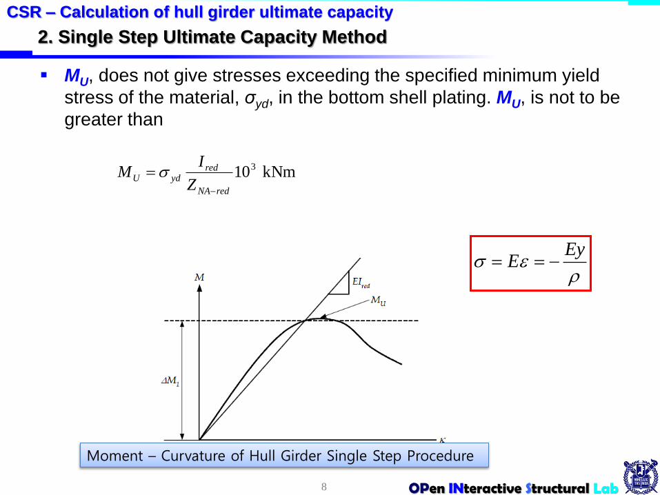
MU, does not give stresses exceeding the specified minimum yield
stress of the material, σyd, in the bottom shell plating. MU, is not to be
greater than
8
CSR – Calculation of hull girder ultimate capacity
kNm103
redNA
redydU
Z
IM
Moment – Curvature of Hull Girder Single Step Procedure
EyE
OPen INteractive Structural Lab
2. Single Step Ultimate Capacity Method
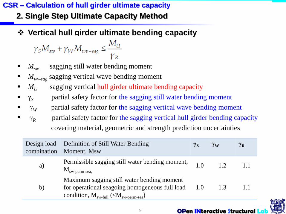
Vertical hull girder ultimate bending capacity
Msw sagging still water bending moment
Mwv-sag sagging vertical wave bending moment
MU sagging vertical hull girder ultimate bending capacity
γS partial safety factor for the sagging still water bending moment
γW partial safety factor for the sagging vertical wave bending moment
γR partial safety factor for the sagging vertical hull girder bending capacity
covering material, geometric and strength prediction uncertainties
9
CSR – Calculation of hull girder ultimate capacity
Design load
combination
Definition of Still Water Bending
Moment, Msw
γS γW γR
a)Permissible sagging still water bending moment,
Msw-perm-sea,
1.0 1.2 1.1
b)
Maximum sagging still water bending moment
for operational seagoing homogeneous full load
condition, Msw-full (<Msw-perm-sea)
1.0 1.3 1.1
OPen INteractive Structural Lab
3. Simplified Method Based on an Incremental-iterative Approach
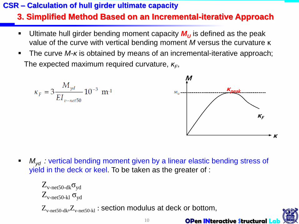
Ultimate hull girder bending moment capacity MU is defined as the peak
value of the curve with vertical bending moment M versus the curvature κ
The curve M-κ is obtained by means of an incremental-iterative approach;
The expected maximum required curvature, κF,
Myd : vertical bending moment given by a linear elastic bending stress of
yield in the deck or keel. To be taken as the greater of :
10
CSR – Calculation of hull girder ultimate capacity
κ
M
κF
κpeak
Zv-net50-dk,Zv-net50-kl : section modulus at deck or bottom,
Zv-net50-dkσyd
Zv-net50-kl σyd
OPen INteractive Structural Lab
Assumptions and modeling of the hull girder cross-section
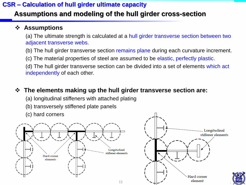
Assumptions
(a) The ultimate strength is calculated at a hull girder transverse section between two
adjacent transverse webs.
(b) The hull girder transverse section remains plane during each curvature increment.
(c) The material properties of steel are assumed to be elastic, perfectly plastic.
(d) The hull girder transverse section can be divided into a set of elements which act
independently of each other.
The elements making up the hull girder transverse section are:
(a) longitudinal stiffeners with attached plating
(b) transversely stiffened plate panels
(c) hard corners
11
CSR – Calculation of hull girder ultimate capacity

OPen INteractive Structural Lab12
CSR – Calculation of hull girder ultimate capacity
Calculate elastic section modulus and
position of the neutral axis, zna
Initialize curvature κi = Δκ
Derive maximum curvature κF
For all structural elements (index = j)
Start
Exit loop when the
adjustment of the
neutral axis is less
than 0.0001
Derive the total force on the transverse
section Fi = ΣσjAj
For each structural element calculate the
stress σj relevant to the strain ε
Calculate the strain εij induced on each
structural element by the curvature κi about
the neutral axis position zna-i
Calculation of the bending moment Mi
relevant to the curvature κi summing the
contribution of each structural element stress
Curve M - κ
The ultimate capacity is the peak
value, Mu, from the M - κ curve
κ = κF
Increase curvaturei = i+1
κi= κi-1 + ΔκzNA-I = zNA-i+1
Adjust the position
of the neutral axis
based on Fi
Overall Procedure

OPen INteractive Structural Lab
ε
σ
compression or
shortening
tension orlengthening
ε
σ
tension orlengthening
Simplified Method Based on an Incremental-iterative Approach
13
CSR – Calculation of hull girder ultimate capacity
ε
N.A.-i
zNA-i
Iκi
Stress strain curve σ-ε for elastic, perfectly plastic failure of a hard corner
Typical stress strain curve σ-ε for elasto-plastic failure of a stiffener
compression or
shortening
Calculate the strain εij induced on each
structural element by the curvature κi
about the neutral axis position zna-i
For each structural element calculate thestress σj relevant to the strain ε

OPen INteractive Structural Lab
Simplified Method Based on an Incremental-iterative Approach
Exit loop when
the adjustment of
the neutral axis is
less than 0.0001
CSR – Calculation of hull girder ultimate capacity
σj
N.A.-i
zNA-i
κi `
No
Yes
ε'
N.A.-i'
zNA-I’
κi'
ε
σ
ε
σ
Derive the total force on the
transverse section Fi = ΣσjAj
For each structural element calculate the
stress σj relevant to the strain ε
Calculate the strain εij induced on each
structural element by the curvature κi about
the neutral axis position zna-i
OPen INteractive Structural Lab
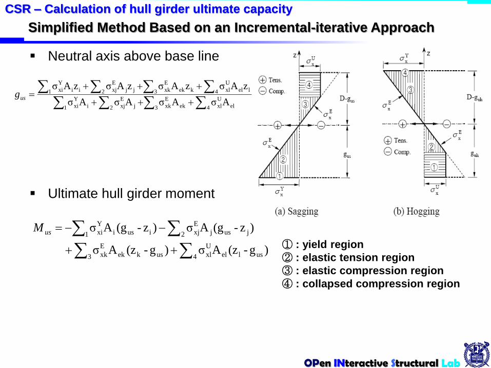
Neutral axis above base line
Ultimate hull girder moment
최종 강도 정식화
① : yield region
② : elastic tension region
③ : elastic compression region
④ : collapsed compression region
Simplified Method Based on an Incremental-iterative Approach
CSR – Calculation of hull girder ultimate capacity
1 3 4 el
U
xlek
E
xk2 j
E
xji
Y
xi
1 3 4 lel
U
xlkek
E
xk2 jj
E
xjii
Y
xi
AσAσAσAσ
zAσzAσzAσzAσusg
3 4 uslel
U
xluskek
E
xk
1 2 jusj
E
xjiusi
Y
xi
)g-(zAσ)g-(zAσ
)z-(gAσ)z-(gAσusM

OPen INteractive Structural Lab
Simplified Method Based on an Incremental-iterative Approach
16
CSR – Calculation of hull girder ultimate capacity
Yes
κ
M
κF
κpeak
ε
N.A.-i+1
zNA-i+1
κi+1
Exit loop when
the adjustment of
the neutral axis is
less than 0.0001
Calculation of the bending moment Mi
relevant to the curvature κi summing the
contribution of each structural element stress
Curve M - κ
The ultimate capacity is the peak
value, Mu, from the M - κ curve
κ = κF
Increase curvaturei = i+1
κi= κi-1 + ΔκzNA-I = zNA-i+1
Yes
No
OPen INteractive Structural Lab
Stress-strain Curves σ-ε (or Load-end Shortening Curves)
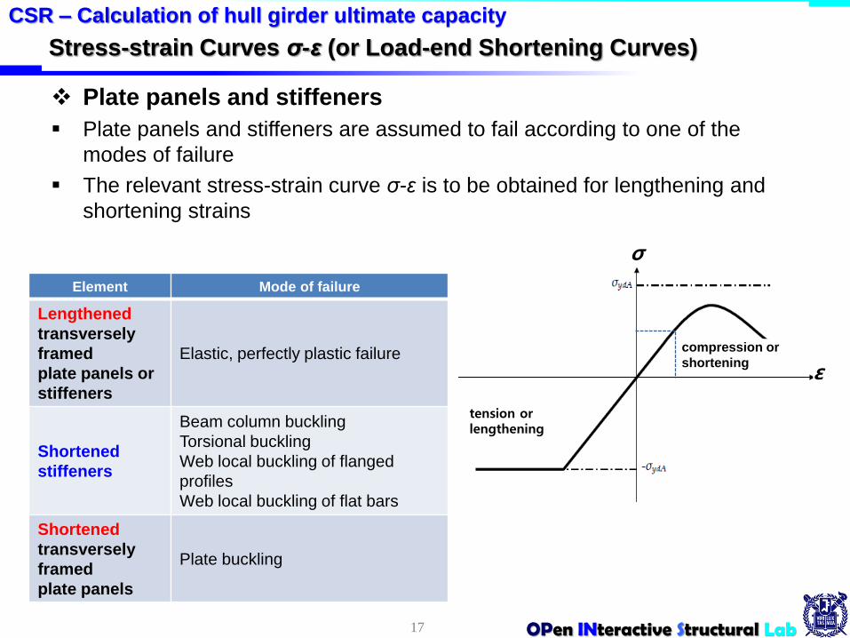
Plate panels and stiffeners
Plate panels and stiffeners are assumed to fail according to one of the
modes of failure
The relevant stress-strain curve σ-ε is to be obtained for lengthening and
shortening strains
17
CSR – Calculation of hull girder ultimate capacity
ε
σ
compression or
shortening
tension orlengthening
Element Mode of failure
Lengthened
transversely
framed
plate panels or
stiffeners
Elastic, perfectly plastic failure
Shortened
stiffeners
Beam column buckling
Torsional buckling
Web local buckling of flanged
profiles
Web local buckling of flat bars
Shortened
transversely
framed
plate panels
Plate buckling

OPen INteractive Structural Lab
Stress-strain Curves σ-ε (or Load-end Shortening Curves)
Hard Corners
Hard corners are sturdier elements which are assumed to buckle and fail in
an elastic, perfectly plastic manner.
18
CSR – Calculation of hull girder ultimate capacity
ε
σ
tension orlengthening
compression or
shortening

OPen INteractive Structural Lab
Stress-strain Curves σ-ε (or Load-end Shortening Curves)
Elasto-plastic failure of structural elements
Beam column buckling
Euler buckling with plasticity correction
19
CSR – Calculation of hull girder ultimate capacity
ε
σ
tension orlengthening
compression or
shortening
OPen INteractive Structural Lab
Stress-strain Curves σ-ε (or Load-end Shortening Curves)
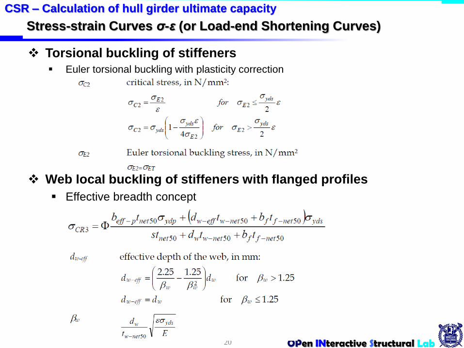
Torsional buckling of stiffeners
Euler torsional buckling with plasticity correction
Web local buckling of stiffeners with flanged profiles
Effective breadth concept
20
CSR – Calculation of hull girder ultimate capacity

OPen INteractive Structural Lab
Stress-strain Curves σ-ε (or Load-end Shortening Curves)
Web local buckling of flat bar stiffeners
Euler torsional buckling with plasticity correction
Web local buckling of flat bar stiffeners
21
CSR – Calculation of hull girder ultimate capacity

OPen INteractive Structural Lab
4. Alternative Methods
Considerations for alternative models
The bending moment-curvature relationship, M-κ, may be established by
alternative methods. Such models are to consider all the relevant effects
important to the non-linear response with due considerations of:
a. non-linear geometrical behaviour
b. inelastic material behaviour
c. geometrical imperfections and residual stresses (geometrical out-of flatness of
plate and stiffeners)
d. simultaneously acting loads:
e. bi-axial compression
f. bi-axial tension
g. shear and lateral pressure
h. boundary conditions
i. interactions between buckling modes
j. interactions between structural elements such as plates, stiffeners, girders etc.
k. post-buckling capacity.
22
CSR – Calculation of hull girder ultimate capacity

OPen INteractive Structural Lab
4. Alternative Methods
Non-linear finite element analysis
FE models are to consider the relevant effects important to the non-linear
responses with due consideration of the items listed in.
Particular attention is to be given to modeling the shape and size of
geometrical imperfections. It is to be ensured that the shape and size of
geometrical imperfections trigger the most critical failure modes.
23
CSR – Calculation of hull girder ultimate capacity

OPen INteractive Structural Lab
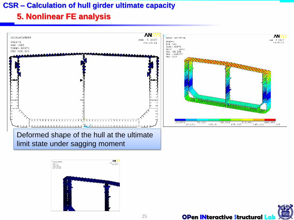
5. Nonlinear FE analysis
Non-linear finite element analysis
50% corrosion margin
Initial deflection of plating of plating(wopl) and stiffener web(wow), elastic
buckling mode
the fabrication related initial distortions of stiffeners
24
Nonlinear FE analysis
200,
200
wowopl
hw
bw
buckling collapse may take place in
vertical members of the hull structure
until the hull girder reaches the
ultimate limit state → fine mesh
modeling for vertical member
Changing neutral axis of the hull
cross-section due to the progressive
collapse of individual structural
components is to be considered.
1000
aww osoc
Wos
Wopl
Wow
wopl
wow
wos
OPen INteractive Structural Lab
5. Nonlinear FE analysis
25
CSR – Calculation of hull girder ultimate capacity
Deformed shape of the hull at the ultimate
limit state under sagging moment

OPen INteractive Structural Lab
FE analysis results
26
CSR – Calculation of hull girder ultimate capacity
-4.0E-004 -2.0E-004 0.0E+000 2.0E-004 4.0E-004
Curvature (1/m)
-2.0E+010
-1.5E+010
-1.0E+010
-5.0E+009
0.0E+000
5.0E+009
1.0E+010
1.5E+010
Ve
rtic
al b
en
din
g m
om
en
t (
Nm
) Muhog_req.=5.768 GNm
Musag_req.= -7.686 GNm
Muhog_CSR=11.049 GNm
Musag_CSR= -8.540 GNm
Muhog_HULL (Pre-CSR)=8.557 GNm
Musag_HULL (Pre-CSR)= -7.694 GNm
Muhog_HULL (CSR)=9.465 GNm
Musag_HULL (CSR)= -8.329 GNm
CSR structure deducing 50% corrosion margin
Pre-CSR structure deducing 100% corrosion margin
Nonlinear FEA:
CSR structure deducing 50% corrosion margin
ALPS/HULL:
Muhog_FEA=9.554 GNm
Musag_FEA=-8.107 GNm
Hog
Sag
MuHog_FEA
MuHog_CSR
MuHog_Pre-CSR
MuHog_req
MuSag_FEA
MuHog_ISUM
Musog_Pre_CSR
Musag_Req
MuSag_ISUMMuSag_CSR
OPen INteractive Structural Lab
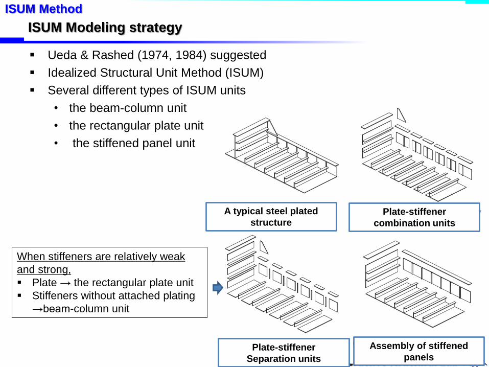
ISUM Modeling strategy
Ueda & Rashed (1974, 1984) suggested
Idealized Structural Unit Method (ISUM)
Several different types of ISUM units
• the beam-column unit
• the rectangular plate unit
• the stiffened panel unit
27
ISUM Method
When stiffeners are relatively weak
and strong,
Plate → the rectangular plate unit
Stiffeners without attached plating
→beam-column unit
Plate-stiffener
combination units
Plate-stiffener
Separation units
Assembly of stiffened
panels
A typical steel plated
structure
OPen INteractive Structural Lab
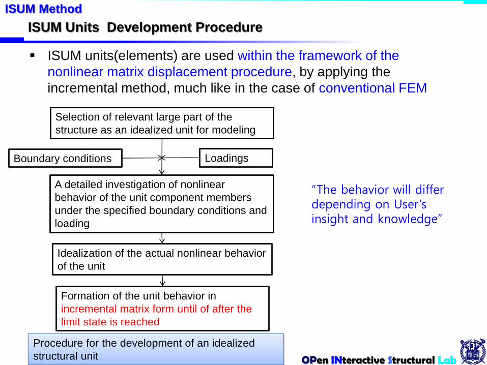
ISUM Units Development Procedure
ISUM units(elements) are used within the framework of the
nonlinear matrix displacement procedure, by applying the
incremental method, much like in the case of conventional FEM
28
ISUM Method
Selection of relevant large part of the
structure as an idealized unit for modeling
A detailed investigation of nonlinear
behavior of the unit component members
under the specified boundary conditions and
loading
Idealization of the actual nonlinear behavior
of the unit
Formation of the unit behavior in
incremental matrix form until of after the
limit state is reached
Boundary conditions Loadings
Procedure for the development of an idealized
structural unit
“The behavior will differ depending on User’s insight and knowledge”
OPen INteractive Structural Lab
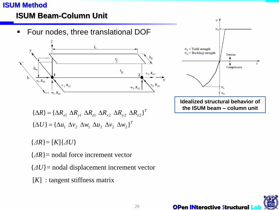
ISUM Beam-Column Unit
Four nodes, three translational DOF
29
ISUM Method
{ΔR}= [K]{ΔU}
{ΔR}= nodal force increment vector
{ΔU}= nodal displacement increment vector
[K] : tangent stiffness matrix
Idealized structural behavior of
the ISUM beam – column unit
T
T
zyxzyx
wvuwvuU
RRRRRRR
}{}{
}{}{
222121
222111
OPen INteractive Structural Lab
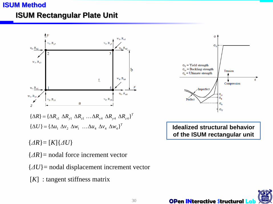
ISUM Rectangular Plate Unit
30
ISUM Method
T
T
zyxzyx
wvuwvuU
RRRRRRR
}{}{
}{}{
444121
444111
Idealized structural behavior
of the ISUM rectangular unit
{ΔR}= [K]{ΔU}
{ΔR}= nodal force increment vector
{ΔU}= nodal displacement increment vector
[K] : tangent stiffness matrix
OPen INteractive Structural Lab
ISUM Method
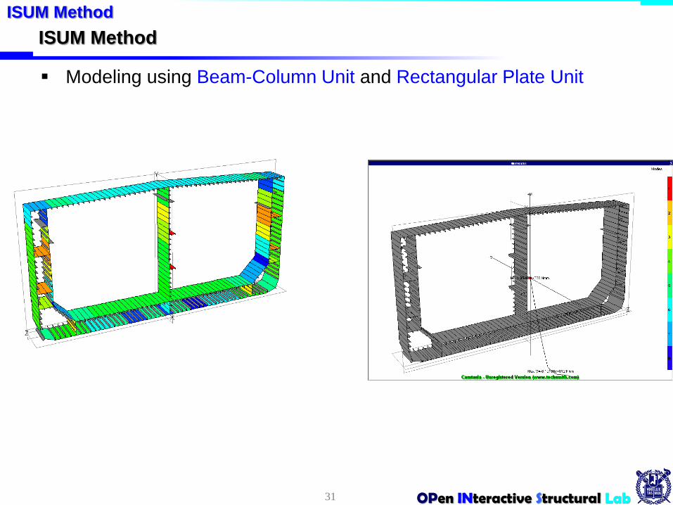
Modeling using Beam-Column Unit and Rectangular Plate Unit
31
ISUM Method

OPen INteractive Structural Lab
Double Hull Tanker Example
The collapse of the compression flange of the tanker hulls takes place prior to the
yielding of the tension flange as in design of usual ship structures
32
ISUM Method
Sagging
For sagging:
11. Buckling collapse of upper inner side shell longl.*
12. Buckling collapse of lower longitudinal bulkhead longl.*
13. Buckling collapse of deck girder longl.
14. Buckling collapse of upper outer shell longl.
15. Buckling collapse of upper inner side shell longl. & deck plates*
16. Buckling collapse of deck plates & longitudinal bulkhead plates*
17. Buckling collapse of deck plates & upper inner/outer shell plates* (Ultimate limit state)
Note: * denotes that the related failure event starts.
Level of initial imperfections:
①: Slight
②: Average
313,000 DWT double hull tanker
OPen INteractive Structural Lab
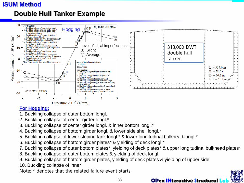
Double Hull Tanker Example
33
ISUM Method
Hogging
For Hogging:
1. Buckling collapse of outer bottom longl.
2. Buckling collapse of center girder longl.*
3. Buckling collapse of center girder longl. & inner bottom longl.*
4. Buckling collapse of bottom girder longl. & lower side shell longl.*
5. Buckling collapse of lower sloping tank longl.* & lower longitudinal bulkhead longl.*
6. Buckling collapse of bottom girder plates* & yielding of deck longl.*
7. Buckling collapse of outer bottom plates*, yielding of deck plates* & upper longitudinal bulkhead plates*
8. Buckling collapse of outer bottom plates & yielding of deck longl.
9. Buckling collapse of bottom girder plates, yielding of deck plates & yielding of upper side
10. Buckling collapse of inner
Note: * denotes that the related failure event starts.
Level of initial imperfections:
①: Slight
②: Average
313,000 DWT double hull tanker

OPen INteractive Structural Lab
Other Examples
34
ISUM Method
254,000 DWT single hull tanker
Sagging
Sagging
105,000 DWT double hull tanker

OPen INteractive Structural Lab
Other Examples
35
ISUM Method
169,000 DWT doublesided bulk carrier
9,000 TEU container
Sagging
Hogging
Hogging