led light guide panel · led light guide panel installation guide 1 of 5 ig122-1. ® led light...
TRANSCRIPT

1 OF 5 IG012820-1.0LED LIGHT GUIDE PANEL INSTALLATION GUIDE
® LED LIGHT GUIDE PANELINSTALLATION GUIDE
SKU DI-LGP-4Input 24VDC or 12VDC
Ambient Temp † -4° - 140°F (-20° - 60°C)
QUICK SPECS / MODELS
† Do not install product in environment outside listed temperature.
*NOT FOR USE IN SUBMERSIBLE APPLICATIONS, OR WITHIN 5 FEET OF A SWIMMING POOL.
DRY LOCATION DIMMABLE
12VDC
SAFETY & WARNINGS1. READ AND FOLLOW ALL SAFETY INSTRUCTIONS2. Install in accordance with national and local electrical code
regulations.3. This product is intended to be installed and serviced by a
qualified, licensed electrician.4. Do not use if there is any damage to fixture or wiring. Inspect
periodically.5. Do not submerge fixture in liquids or use the product in the
vicinity of standing water or other liquids.6. Do not install near areas with exposure to salt water or
chlorinated water.7. Do not install in direct sunlight or damage to the LED
phosphor will occur.8. Do not attempt to fix this product in the field.9. Failure to follow safety warnings and installation instructions
will void the warranty for this product.10. Light Guide Panels are not load bearing. Do not use to hold
objects, as a shelf, or as a support.
24VDC
Note: Handle panels larger than 24 x 36 in. vertically or frame may bend. Prior to installation, ensure all components create a compatible system. Configure and pre-test your LED system prior to permanent installation to ensure all components are operating correctly.
2 OF 5 IG012820-1.0LED LIGHT GUIDE PANEL INSTALLATION GUIDE
LED LIGHT GUIDE PANELINSTALLATION GUIDE
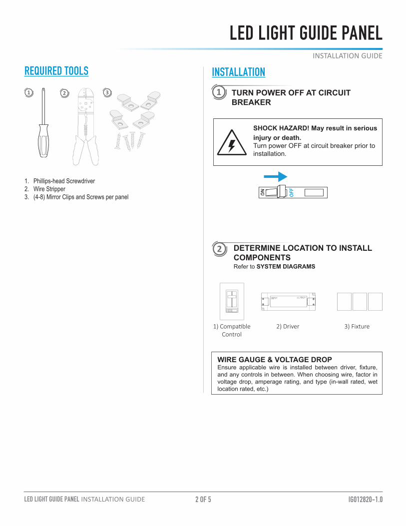
INSTALLATION
TURN POWER OFF AT CIRCUIT BREAKER
SHOCK HAZARD! May result in serious injury or death.Turn power OFF at circuit breaker prior to installation.
REQUIRED TOOLS
1 2 3
1. Phillips-head Screwdriver2. Wire Stripper3. (4-8) Mirror Clips and Screws per panel
DETERMINE LOCATION TO INSTALL COMPONENTS
1
2
WIRE GAUGE & VOLTAGE DROPEnsure applicable wire is installed between driver, fixture, and any controls in between. When choosing wire, factor in voltage drop, amperage rating, and type (in-wall rated, wet location rated, etc.)
L
N
V+
V-
1) Compatible Control
2) Driver 3) Fixture
Refer to SYSTEM DIAGRAMS

3 OF 5 IG012820-1.0LED LIGHT GUIDE PANEL INSTALLATION GUIDE
LED LIGHT GUIDE PANELINSTALLATION GUIDE
INSTALLATION (CONT.)
MOUNT LED LIGHT GUIDE PANEL TO SURFACE
Using mirror clips, (not included) mount panel to surface as you would a mirror.
3
iFIT Panels Display Graphic
Front Profile Side Profile
4 MULTIPLE PANEL MOUNTINGTo achieve even light distribution, install a diffuser or place the graphic image a reasonable distance from the panel. Distance will vary as each panel is built to custom specifications.
5 ATTACH DRIVER AND LIGHTING CONTROL.Verify a compatible driver is installed. Utilize applicable wiring when installing outdoors. (Use of wet location-rated junction box recommended)
TROUBLESHOOTING
TOOLS & RESOURCESLIGHT GUIDE PANEL SPECIFICATION SHEETFor full specifications.
Shift in brightness and/or kelvin
• Ensure an appropriate gauge of wire is installed between strip light and LED driver. See VOLTAGE DROP CHARTS.
Some LEDs are not functional
• Ensure strip light has not been bent excessively, which could damage circuitry.
Lights are flickering
• Ensure a compatible driver and/or dimming control is installed. Check for loose connections.
Lights are turning on/off repeatedly
• Ensure driver is not overloaded. An overloaded driver will trip the internal auto-reset (of driver) repeatedly, turning the system on/off.
TURN POWER ON AT CIRCUIT BREAKER6
4 OF 5 IG012820-1.0LED LIGHT GUIDE PANEL INSTALLATION GUIDE
LED LIGHT GUIDE PANELINSTALLATION GUIDE
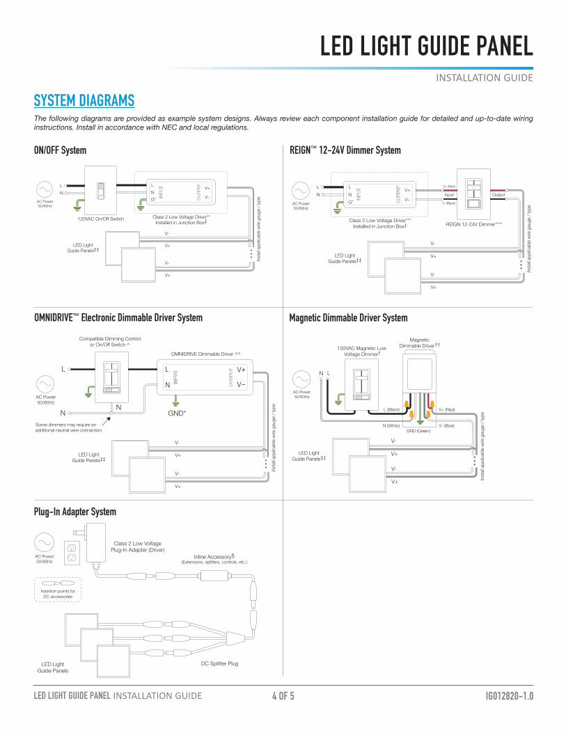
SYSTEM DIAGRAMS
AC Power50/60Hz
120VAC Magnetic Low Voltage Dimmer†
V+ (Red)
V- (Blue)
LN
N (White)
L (Black)
Magnetic Dimmable Driver††
Inst
all a
pplic
able
wire
gau
ge /
type
V+
V-
V+
V-
GND (Green)
LED Light Guide Panels‡‡
Magnetic Dimmable Driver System
The following diagrams are provided as example system designs. Always review each component installation guide for detailed and up-to-date wiring instructions. Install in accordance with NEC and local regulations.
Some dimmers may require an additional neutral wire connection.
V+
V-
V+
V- Inst
all a
pplic
able
wire
gau
ge /
type
LED Light Guide Panels‡‡
AC Power50/60Hz
Compatible Dimming Control or On/Off Switch ^
L
OMNIDRIVE Dimmable Driver ^^
NN
GND*
N
L V+
V−
REIGN™ 12-24V Dimmer System
OMNIDRIVE™ Electronic Dimmable Driver System
V+
V-
V+
V- Inst
all a
pplic
able
wire
gau
ge /
type
LED Light Guide Panels‡‡
G*NL
V+
V−
Class 2 Low Voltage Driver*** Installed in Junction Box‡
V- (Black)
Input Output
V+ (Red)
REIGN 12-24V Dimmer****
LN
AC Power50/60Hz
V+
V-
V+
V-
LN
G*NL
V+
V−
120VAC On/Off Switch Class 2 Low Voltage Driver** Installed in Junction Box‡
Inst
all a
pplic
able
wire
gau
ge /
type
AC Power50/60Hz
LED Light Guide Panels‡‡
ON/OFF System
DC Splitter PlugLED LightGuide Panels
Class 2 Low Voltage Plug-In Adapter (Driver)
AC Power50/60Hz
Insertion points for DC accessories
Inline Accessory§(Extensions, splitters, controls, etc.)
Plug-In Adapter System

5 OF 5
® Toll Free: 877.817.6028 | Fax: 415.592.1596 | www.DiodeLED.com | [email protected]© 2020 Elemental LED Inc. All rights reserved. Specifications are subject to change without notice.
IG012820-1.0LED LIGHT GUIDE PANEL INSTALLATION GUIDE
LED LIGHT GUIDE PANELINSTALLATION GUIDE
Wire Gauge
10 W.42 A
20 W.83 A
30 W1.3 A
40 W1.7 A
50 W2.1 A
60 W2.5 A
22 AWG 53 ft. 27 ft. 17 ft. 13 ft. 11 ft. 9 ft.
18 AWG 134 ft. 68 ft. 45 ft. 33 ft. 27 ft. 22 ft.
16 AWG 215 ft. 109 ft. 72 ft. 54 ft. 43 ft. 36 ft.
14 AWG 345 ft. 174 ft. 115 ft. 86 ft. 69 ft. 57 ft.
12 AWG 539 ft. 272 ft. 181 ft. 135 ft. 108 ft. 90 ft.
10 AWG 784 ft. 397 ft. 263 ft. 197 ft. 158 ft. 131 ft.
Wire Gauge
10 W.42 A
20 W.83 A
30 W1.3 A
40 W1.7 A
50 W2.1 A
60 W2.5 A
70 W2.9 A
80 W3.3 A
100 W4. 2 A
22 AWG 53 ft. 27 ft. 17 ft. 13 ft. 11 ft. 9 ft. 8 ft. 7 ft. 6 ft.
18 AWG 134 ft. 68 ft. 45 ft. 33 ft. 27 ft. 22 ft. 19 ft. 17 ft. 14 ft.
16 AWG 215 ft. 109 ft. 72 ft. 54 ft. 43 ft. 36 ft. 31 ft. 27 ft. 22 ft.
14 AWG 345 ft. 174 ft. 115 ft. 86 ft. 69 ft. 57 ft. 49 ft. 43 ft. 36 ft.
12 AWG 539 ft. 272 ft. 181 ft. 135 ft. 108 ft. 90 ft. 77 ft. 68 ft. 56 ft.
10 AWG 784 ft. 397 ft. 263 ft. 197 ft. 158 ft. 131 ft. 112 ft. 98 ft. 82 ft.
24V Voltage Drop & Wire Length Distance Chart
Example: 24V Voltage Drop & Wire Length Distance Chart Determine load size. Let’s assume load is 55 W. Round up to nearest load.
1
Determine distance from driver to load. Let’s assume the distance is 90 ft.
2
It is recommended to install 12 AWG to eliminate excess voltage drop.3
VOLTAGE DROP CHARTSFor best performance and lumen output, ensure proper wire gauge is installed to compensate for voltage drop of low voltage circuits.