legend “s” series blowers | 6” gear diameter parts list
TRANSCRIPT
PD BLOWERS & VACUUM PUMPS LEGEND “S” SERIES BLOWERS | 6” GEAR DIAMETER
Parts List, Operating &Service Manual
LEGEND ‘‘S’’ SERIES6’’ GEAR DIAMETER
SB-7-635 Version 01
April 23, 2018
Models
GAF_ _S_


SB-7-635 Page 2
MAINTAIN BLOWER RELIABILITY AND PERFORMANCE WITH GENUINE GARDNER DENVER PARTS AND SUPPORT SERVICES
Factory genuine parts, manufactured to design tolerances, are developed for optimum dependability - - - specifically for your blower. Design and material innovations are born from years of experience with hundreds of different blower applications. When you specify factory genuine parts you are assured of receiving parts that incorporate the most current design advancements manufactured in our state-of-the-art blower factory under exacting quality standards. Your AUTHORIZED DISTRIBUTOR offers all the backup you require. A worldwide network of authorized distributors provides the finest product support in the blower industry.
1. Trained technical representatives to assist you in selecting the correct replacement parts.
2. Complete inventory of new machines and new, genuine factory parts.
3. A full line of factory tested AEON® PD blower lubricants, specifically formulated for optimum performance in all blowers.
4. Authorized distributor service technicians are factory-trained and skilled in blower maintenance and
repair. They are ready to respond and assist you by providing fast, expert maintenance and repair service.
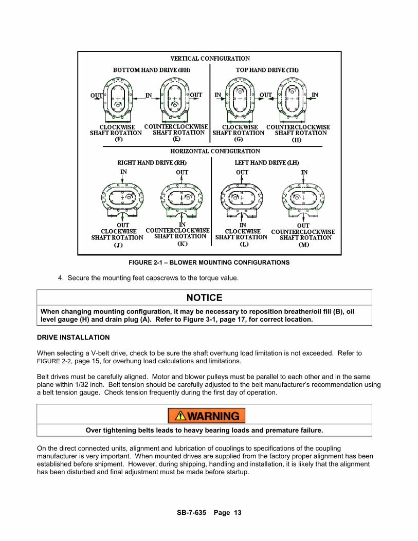
INSTRUCTIONS FOR DETERMINING BLOWER CONFIGURATION
1. Face the blower drive shaft. 2. In a VERTICAL configuration, air flow is horizontal. 3. In a HORIZONTAL configuration, air flow is vertical. 4. In a vertical configuration, a BOTTOM HAND exists when the drive shaft is below the horizontal
center line of the blower. A TOP HAND exits when the drive shaft is above the horizontal center line of the blower.
5. In a horizontal configuration, a RIGHT HAND exists when the drive shaft is to the right of the vertical center line of the blower. A LEFT HAND exists when the drive shaft is to the left of the vertical center line of the blower.
INSTRUCTIONS FOR ORDERING REPAIR PARTS
For pricing, and ordering information contact your nearest AUTHORIZED FACTORY DISTRIBUTOR. When ordering parts, specify Blower MODEL and SERIAL NUMBER (see nameplate on unit). Rely upon the knowledge and experience of your AUTHORIZED DISTRIBUTOR and let them assist you in making the proper parts selection for your blower.
To Contact Gardner Denver or locate your local distributor: Visit: www.gardnerdenver.com/gdproducts
Or
Call: - (800)372-2222
SB-7-635 Page 3
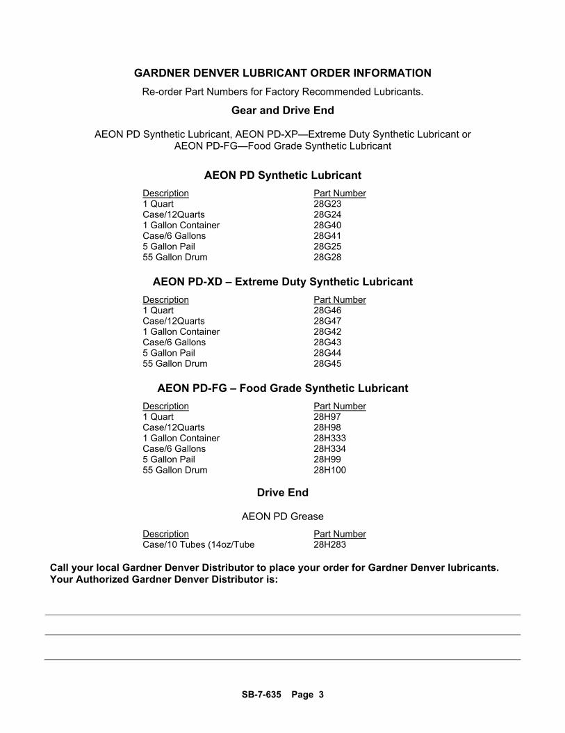
GARDNER DENVER LUBRICANT ORDER INFORMATION
Re-order Part Numbers for Factory Recommended Lubricants.
Gear and Drive End
AEON PD Synthetic Lubricant, AEON PD-XP—Extreme Duty Synthetic Lubricant or AEON PD-FG—Food Grade Synthetic Lubricant
AEON PD Synthetic Lubricant
Description Part Number 1 Quart 28G23 Case/12Quarts 28G24 1 Gallon Container 28G40 Case/6 Gallons 28G41 5 Gallon Pail 28G25 55 Gallon Drum 28G28
AEON PD-XD – Extreme Duty Synthetic Lubricant
Description Part Number 1 Quart 28G46 Case/12Quarts 28G47 1 Gallon Container 28G42 Case/6 Gallons 28G43 5 Gallon Pail 28G44 55 Gallon Drum 28G45
AEON PD-FG – Food Grade Synthetic Lubricant
Description Part Number 1 Quart 28H97 Case/12Quarts 28H98 1 Gallon Container 28H333 Case/6 Gallons 28H334 5 Gallon Pail 28H99 55 Gallon Drum 28H100
Drive End
AEON PD Grease
Description Part Number Case/10 Tubes (14oz/Tube 28H283
Call your local Gardner Denver Distributor to place your order for Gardner Denver lubricants. Your Authorized Gardner Denver Distributor is:

SB-7-635 Page 4
FOREWORD Sutorbilt blowers are the result of advanced engineering and skilled manufacturing. To be assured of receiving maximum service from this machine, the owner must exercise care in its operation and maintenance. This manual is written to give the operator and maintenance department essential information for day-to-day operation, maintenance and adjustment. Careful adherence to these instructions will result in economical operation and minimum downtime.
Danger is used to indicate the presence of a hazard which will cause severe personal injury, death, or substantial property damage if the warning is ignored.
Warning is used to indicate the presence of a hazard which can cause severe personal injury, death, or substantial property damage if the warning is ignored.
Caution is used to indicate the presence of a hazard which will or can cause minor personal injury or property damage if the warning is ignored.
NOTICE Notice is used to notify people of installation, operation or maintenance information which is important but not hazard-related.
SB-7-635 Page 5
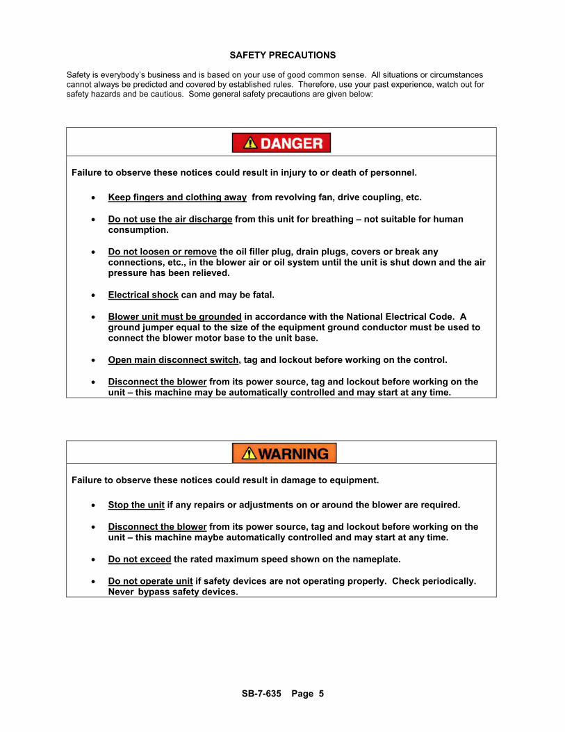
SAFETY PRECAUTIONS Safety is everybody’s business and is based on your use of good common sense. All situations or circumstances cannot always be predicted and covered by established rules. Therefore, use your past experience, watch out for safety hazards and be cautious. Some general safety precautions are given below:
Failure to observe these notices could result in injury to or death of personnel.
Keep fingers and clothing away from revolving fan, drive coupling, etc.
Do not use the air discharge from this unit for breathing – not suitable for human
consumption.
Do not loosen or remove the oil filler plug, drain plugs, covers or break any connections, etc., in the blower air or oil system until the unit is shut down and the air pressure has been relieved.
Electrical shock can and may be fatal.
Blower unit must be grounded in accordance with the National Electrical Code. A
ground jumper equal to the size of the equipment ground conductor must be used to connect the blower motor base to the unit base.
Open main disconnect switch, tag and lockout before working on the control.
Disconnect the blower from its power source, tag and lockout before working on the
unit – this machine may be automatically controlled and may start at any time.
Failure to observe these notices could result in damage to equipment.
Stop the unit if any repairs or adjustments on or around the blower are required.
Disconnect the blower from its power source, tag and lockout before working on the
unit – this machine maybe automatically controlled and may start at any time.
Do not exceed the rated maximum speed shown on the nameplate.
Do not operate unit if safety devices are not operating properly. Check periodically. Never bypass safety devices.

SB-7-635 Page 6
TABLE OF CONTENTS MAINTAIN BLOWER RELIABILITY AND PERFORMANCE..................................................................................... 2
FOREWORD ............................................................................................................................................................. 4
SAFETY PRECAUTIONS .......................................................................................................................................... 5
SUTORBILT LEGEND SERIES BLOWERS ............................................................................................................. 8
INTRODUCTION ....................................................................................................................................................... 9
SECTION 1, EQUIPMENT CHECK ......................................................................................................................... 10
SECTION 2, INSTALLATION .................................................................................................................................. 12
AIR FILTERS AND FILTER SILENCERS ............................................................................................................... 16
SECTION 3, LUBRICATION ................................................................................................................................... 17
RECOMMENDED LUBRICANT .............................................................................................................................. 20
SECTION 4, OPERATION ...................................................................................................................................... 22
SECTION 5, TOOLS – DISASSEMBLY/ASSEMBLY/SPECIAL ............................................................................. 25
SECTION 6, ASSEMBLY INSTRUCTIONS ............................................................................................................ 28
SECTION 7, SPECIAL TOOLS REQUIRED ........................................................................................................... 29
SECTION 8, DISASSEMBLY INSTRUCTIONS ...................................................................................................... 49
SECTION 9, PARTS LIST ......................................................................................... Error! Bookmark not defined.
WARRANTY ............................................................................................................................................................ 59
SB-7-635 Page 7
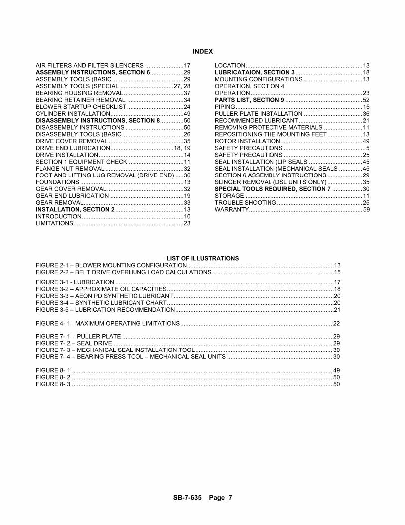
INDEX
AIR FILTERS AND FILTER SILENCERS ....................... 17 ASSEMBLY INSTRUCTIONS, SECTION 6 .................... 29 ASSEMBLY TOOLS (BASIC ........................................... 29 ASSEMBLY TOOLS (SPECIAL ................................ 27, 28 BEARING HOUSING REMOVAL .................................... 37 BEARING RETAINER REMOVAL .................................. 34 BLOWER STARTUP CHECKLIST .................................. 24 CYLINDER INSTALLATION ............................................ 49 DISASSEMBLY INSTRUCTIONS, SECTION 8 .............. 50 DISASSEMBLY INSTRUCTIONS ................................... 50 DISASSEMBLY TOOLS (BASIC ..................................... 26 DRIVE COVER REMOVAL ............................................. 35 DRIVE END LUBRICATION ...................................... 18, 19 DRIVE INSTALLATION ................................................... 14 SECTION 1 EQUIPMENT CHECK ................................. 11 FLANGE NUT REMOVAL ............................................... 32 FOOT AND LIFTING LUG REMOVAL (DRIVE END) ..... 36 FOUNDATIONS .............................................................. 13 GEAR COVER REMOVAL .............................................. 32 GEAR END LUBRICATION ............................................ 19 GEAR REMOVAL............................................................ 33 INSTALLATION, SECTION 2 ......................................... 13 INTRODUCTION ............................................................. 10 LIMITATIONS .................................................................. 23
LOCATION ...................................................................... 13 LUBRICATAION, SECTION 3 ........................................ 18 MOUNTING CONFIGURATIONS ................................... 13 OPERATION, SECTION 4 OPERATION ................................................................... 23 PARTS LIST, SECTION 9 .............................................. 52 PIPING ............................................................................ 15 PULLER PLATE INSTALLATION ................................... 36 RECOMMENDED LUBRICANT ...................................... 21 REMOVING PROTECTIVE MATERIALS ....................... 11 REPOSITIONING THE MOUNTING FEET ..................... 13 ROTOR INSTALLATION ................................................. 49 SAFETY PRECAUTIONS ................................................. 5 SAFETY PRECAUTIONS ............................................... 25 SEAL INSTALLATION (LIP SEALS ................................ 45 SEAL INSTALLATION (MECHANICAL SEALS .............. 45 SECTION 6 ASSEMBLY INSTRUCTIONS ..................... 29 SLINGER REMOVAL (DSL UNITS ONLY) ..................... 35 SPECIAL TOOLS REQUIRED, SECTION 7 .................. 30 STORAGE ...................................................................... 11 TROUBLE SHOOTING ................................................... 25 WARRANTY.................................................................... 59
LIST OF ILLUSTRATIONS FIGURE 2-1 – BLOWER MOUNTING CONFIGURATION ........................................................................................13 FIGURE 2-2 – BELT DRIVE OVERHUNG LOAD CALCULATIONS .........................................................................15
FIGURE 3-1 - LUBRICATION ...................................................................................................................................17 FIGURE 3-2 – APPROXIMATE OIL CAPACITIES ....................................................................................................18 FIGURE 3-3 – AEON PD SYNTHETIC LUBRICANT ................................................................................................20 FIGURE 3-4 – SYNTHETIC LUBRICANT CHART ....................................................................................................20 FIGURE 3-5 – LUBRICATION RECOMMENDATION ...............................................................................................21 FIGURE 4- 1– MAXIMUM OPERATING LIMITATIONS ........................................................................................... 22
FIGURE 7- 1 – PULLER PLATE .............................................................................................................................. 29 FIGURE 7- 2 – SEAL DRIVE ................................................................................................................................... 29 FIGURE 7- 3 – MECHANICAL SEAL INSTALLATION TOOL .................................................................................. 30 FIGURE 7- 4 – BEARING PRESS TOOL – MECHANICAL SEAL UNITS ............................................................... 30 FIGURE 8- 1 ............................................................................................................................................................ 49 FIGURE 8- 2 ............................................................................................................................................................ 50 FIGURE 8- 3 ............................................................................................................................................................ 50
SB-7-635 Page 8
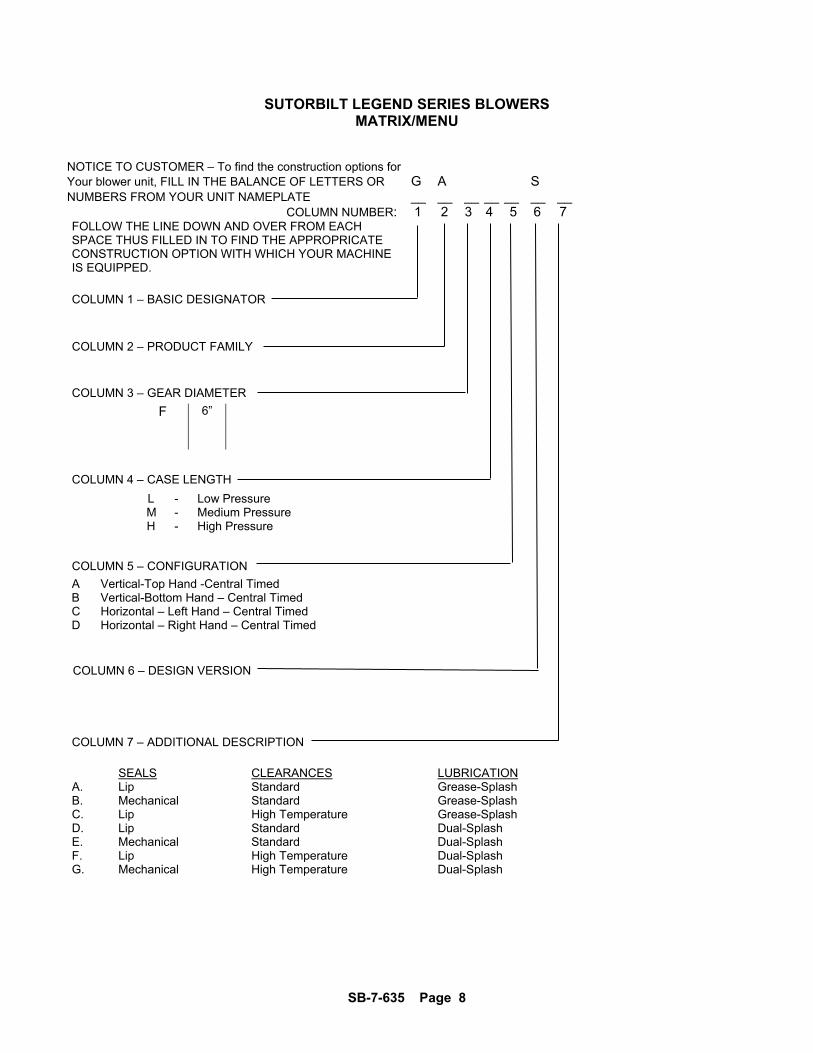
SUTORBILT LEGEND SERIES BLOWERS MATRIX/MENU
NOTICE TO CUSTOMER – To find the construction options for Your blower unit, FILL IN THE BALANCE OF LETTERS OR G A S NUMBERS FROM YOUR UNIT NAMEPLATE __ __ __ __ __ __ __
COLUMN NUMBER: 1 2 3 4 5 6 7 FOLLOW THE LINE DOWN AND OVER FROM EACH SPACE THUS FILLED IN TO FIND THE APPROPRICATE CONSTRUCTION OPTION WITH WHICH YOUR MACHINE IS EQUIPPED.
COLUMN 1 – BASIC DESIGNATOR
COLUMN 2 – PRODUCT FAMILY
COLUMN 3 – GEAR DIAMETER
F 6”
COLUMN 4 – CASE LENGTH
L - Low Pressure M - Medium Pressure H - High Pressure
COLUMN 5 – CONFIGURATION
A Vertical-Top Hand -Central Timed B Vertical-Bottom Hand – Central Timed C Horizontal – Left Hand – Central Timed D Horizontal – Right Hand – Central Timed
COLUMN 6 – DESIGN VERSION
COLUMN 7 – ADDITIONAL DESCRIPTION
SEALS CLEARANCES LUBRICATION
A. Lip Standard Grease-Splash B. Mechanical Standard Grease-Splash C. Lip High Temperature Grease-Splash D. Lip Standard Dual-Splash E. Mechanical Standard Dual-Splash F. Lip High Temperature Dual-Splash G. Mechanical High Temperature Dual-Splash
SB-7-635 Page 9
INTRODUCTION YOUR KEY TO TROUBLE FREE SERVICE
Thank you for investing in Gardner Denver quality. The Gardner Denver reputation for rugged dependability has been earned by over 50 years of service in demanding, industrial operations where downtime cannot be tolerated and efficient blower performance is expected. Your Gardner Denver Sutorbilt blower is a precision engineered blower that has been carefully manufactured and thoroughly tested at the state-of the art Gardner Denver Blower Factory in Sedalia, Missouri. As with other precision machinery, there are several relatively simple installation, operation and maintenance procedures that you must observe to assure optimum blower performance. There is no guesswork in the manufacture of your highly advanced Sutorbilt blower and there must be none in preparing the blower to get the job done in the field. The purpose of this manual is to help you properly install, operate and maintain your Sutorbilt blower. It is essential that you review all sections of this manual in preparation for installing your blower. Follow the instructions for installing your blower. Follow the instructions carefully and you will be rewarded with trouble-free Gardner Denver Sutorbilt service year in and year out.
SB-7-635 Page 10
SECTION 1 EQUIPMENT CHECK
Before uncrating, check the packing slip carefully to be sure all the parts have been received. All accessories are listed as separate items on the packing slip, and small important accessories such as relief valves can be overlooked or lost. After every item on the packing slip has been checked off, uncrate carefully.
NOTICE Register a claim with the carrier for lost or damaged equipment.
Customers are cautioned to provide adequate protection, warning and safety equipment necessary to protect personnel against hazards involved in installation and operation of this equipment in the system or facility.
STORAGE
Your Gardner Denver Blower was packaged at the factory with adequate protection to permit normal storage for up to six (6) months.
If the unit is to be stored under adverse conditions or for extended periods of time, the following additional measures should be taken to prevent damage.
1. Store the blower in a clean, dry, heated (if possible) area. 2. Make certain inlet and discharge air ports are tightly covered to prevent foreign material from entering the air box. 3. All exposed, non-painted surfaces should be protected against rust and corrosion. 4. Provide adequate protection to avoid accidental mechanical damage. 5. In high humidity or corrosive environments, additional measures may be required to prevent rusting of the blower internal surfaces. 6. To prevent rusting of gears, bearings, etc., the oil reservoirs may be filled with normal operating oil.
Before running the blower, drain the oil and replace to the proper operating level with clean, fresh lubricant.
7. Rotate the blower shaft (10 to 25 turns) weekly during storage. Inspect the blower shaft (near the shaft seal area) monthly and spray with rust inhibitor if needed. 8. For long term storage (over six (6) months), contact Gardner Denver Compressor Division Customer Service for recommendations.
REMOVING PROTECTIVE MATERIALS
The shaft extension is protected with rust inhibitor which can be removed with any standard solvent.
Follow the safety directions of the solvent manufacturer.

SB-7-635 Page 11
Blower inlet and outlet are temporarily capped to keep out dirt and other contaminants during shipment. These covers must be removed before start-up. The internal surfaces of all Sutorbilt units are mist sprayed with a rust preventative to protect the machine during shipment. Remove this film upon initial startup, using any commercial safety solvent. Position the blower so that the inlet and discharge connections are in the vertical position (vertical airflow). On vertically mounted units, it will be necessary to lay the unit on its side supporting the ends of the unit so as not to restrict the port on the bottom side. Place a shallow pan on the under side of the unit. With the blower disconnected from power, spray the solvent in the top port, rotating the impellers by spinning the shaft manually. Continue this procedure until the unit is visibly clean.
Rotating components will cause severe injury in case of personal contact. Keep hands and loose clothing away from blower inlet and discharge ports.
SB-7-635 Page 12
SECTION 2 INSTALLATION
LOCATION Install the blower in a well lit, clean dry place with plenty of room for inspection and maintenance. FOUNDATIONS For permanent installation we recommend concrete foundations be provided, and the equipment should be grouted to the concrete. It is necessary that a suitable base be used, such as a steel combination base under blower and motor, or a separate sole plate under each. Before grouting, equipment must be leveled, free of all strains, and anchored so no movement will occur during setting of grout. After grout has completely hardened, a recheck is necessary to compensate for shrinkage, etc. If required, add shims under blower feet after final tightening of foundation anchor bolts to remove strain from the blower housing. Where jack screws or wedges are used during grouting, they must be backed off and wedges removed before final tightening of anchor bolts. Refer to grouting instructions. Where a concrete foundation is not feasible, care must be taken to insure that equipment is firmly anchored to adequate structural members, restricting movement and vibration. MOUNTING CONFIGURATIONS The blower flex-mount design enables horizontal and vertical mounting configurations with top or bottom hand, right or left hand shaft positioning. The units are center timed allowing rotation in either direction (refer to Figure 2-1). REPOSITIONING THE MOUNTING FEET.
1. Position the mounting feet to the desired location and snug the capscrew. 2. Place the blower on its feet on a flat surface. 3. Loosen mounting feet capscrews and level unit up. The bench or blower base flatness should be within .002 of an inch.
NOTICE If the unit is not flat within .002 of an inch, it will be necessary to shim the blower feet at installation.
SB-7-635 Page 13
FIGURE 2-1 – BLOWER MOUNTING CONFIGURATIONS
4. Secure the mounting feet capscrews to the torque value.
NOTICE When changing mounting configuration, it may be necessary to reposition breather/oil fill (B), oil level gauge (H) and drain plug (A). Refer to Figure 3-1, page 17, for correct location.
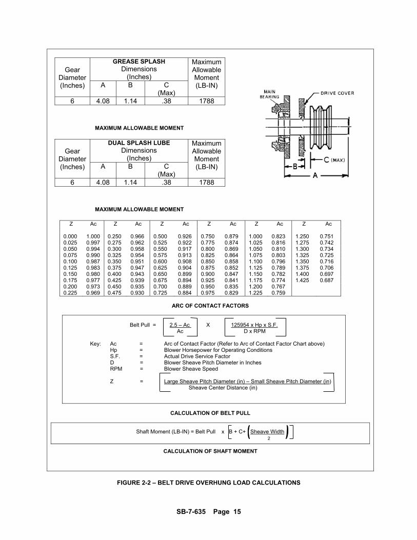
DRIVE INSTALLATION When selecting a V-belt drive, check to be sure the shaft overhung load limitation is not exceeded. Refer to FIGURE 2-2, page 15, for overhung load calculations and limitations. Belt drives must be carefully aligned. Motor and blower pulleys must be parallel to each other and in the same plane within 1/32 inch. Belt tension should be carefully adjusted to the belt manufacturer’s recommendation using a belt tension gauge. Check tension frequently during the first day of operation.
Over tightening belts leads to heavy bearing loads and premature failure.
On the direct connected units, alignment and lubrication of couplings to specifications of the coupling manufacturer is very important. When mounted drives are supplied from the factory proper alignment has been established before shipment. However, during shipping, handling and installation, it is likely that the alignment has been disturbed and final adjustment must be made before startup.
SB-7-635 Page 14
Exceeding overhung load limitations leads to unwarrantable premature bearing failure and shaft breakage.
The location of the sheave on the blower shaft greatly affects the stress in the shaft. The optimum blower sheave positioning is as close as possible to the blower drive cover, not to exceed dimension “C” in Drive Shaft Illustration, FIGURE 2-2, page 15 The calculated shaft moment must not exceed the maximum allowable moment listed in Maximum Allowable Moment Chart, FIGURE 2-2 page 15. If the calculated shaft moment exceed the maximum allowable moment:
Increase Sheave Diameters to Reduce Belt Pull
Use Jackshaft Drive
Use Direct Coupled or Gearbox Drive To calculate shaft moment for a given V-Belt Drive Arrangement:
1. Use the formula for Calculation of Belt Pull, FIGURE 2-2, page 15, to calculate belt pull. Refer to Arc of Contact Factor Chart, Figure 2-2, page 15.
2. Insert the calculated belt pull into the formula for Calculation of Shaft Moment, FIGURE 2-2, page 15 to arrive at the calculated shaft moment.
PIPING Inlet and discharge connections on all blowers are large enough to handle maximum volume with minimum friction loss. Reducing the pipe diameter on either inlet or discharge will only create additional line loss and increase the overall pressure differential. Excessive weight of piping and fittings will cause internal misalignment and premature wear. Never allow the blower to carry the weight of the pipe. If possible, a spool or sleeve-type expansion joint should be installed between the unit and the piping. Where a flexible connection is not practical, the weight of the rigid connection must be separately supported. All system piping must be cleaned internally before connecting to the blower.
Sutorbilt blowers are shipped dry from the factory. Do not attempt to operate the blower before following proper lubrication instructions. Permanent damage to the gears, bearings and seals will occur.
SB-7-635 Page 15
Gear
Diameter (Inches)
GREASE SPLASH Dimensions
(Inches)
MaximumAllowable Moment (LB-IN) A B C
(Max) 6 4.08 1.14 .38 1788
MAXIMUM ALLOWABLE MOMENT
Gear
Diameter (Inches)
DUAL SPLASH LUBE Dimensions
(Inches)
MaximumAllowable Moment (LB-IN) A B C
(Max) 6 4.08 1.14 .38 1788
MAXIMUM ALLOWABLE MOMENT
Z Ac Z Ac Z Ac Z Ac Z Ac Z Ac 0.000 1.000 0.250 0.966 0.500 0.926 0.750 0.879 1.000 0.823 1.250 0.751 0.025 0.997 0.275 0.962 0.525 0.922 0.775 0.874 1.025 0.816 1.275 0.742 0.050 0.994 0.300 0.958 0.550 0.917 0.800 0.869 1.050 0.810 1.300 0.734 0.075 0.990 0.325 0.954 0.575 0.913 0.825 0.864 1.075 0.803 1.325 0.725 0.100 0.987 0.350 0.951 0.600 0.908 0.850 0.858 1.100 0.796 1.350 0.716 0.125 0.983 0.375 0.947 0.625 0.904 0.875 0.852 1.125 0.789 1.375 0.706 0.150 0.980 0.400 0.943 0.650 0.899 0.900 0.847 1.150 0.782 1.400 0.697 0.175 0.977 0.425 0.939 0.675 0.894 0.925 0.841 1.175 0.774 1.425 0.687 0.200 0.973 0.450 0.935 0.700 0.889 0.950 0.835 1.200 0.767 0.225 0.969 0.475 0.930 0.725 0.884 0.975 0.829 1.225 0.759
ARC OF CONTACT FACTORS
Belt Pull = 2.5 – Ac X 125954 x Hp x S.F. Ac D x RPM
Key: Ac = Arc of Contact Factor (Refer to Arc of Contact Factor Chart above) Hp = Blower Horsepower for Operating Conditions S.F. = Actual Drive Service Factor D = Blower Sheave Pitch Diameter in Inches RPM = Blower Sheave Speed Z = Large Sheave Pitch Diameter (in) – Small Sheave Pitch Diameter (in) Sheave Center Distance (in)
CALCULATION OF BELT PULL
Shaft Moment (LB-IN) = Belt Pull x B + C+ Sheave Width
2
CALCULATION OF SHAFT MOMENT
FIGURE 2-2 – BELT DRIVE OVERHUNG LOAD CALCULATIONS
SB-7-635 Page 16
AIR FILTERS AND FILTER SILENCERS
Servicing the air filters is one of the most important maintenance operations to be performed to insure long blower life.
Servicing frequency of filter elements is not time predictable. A differential pressure indicator, with a continuous gauge reading, should be installed across the inlet filter. It will tell how much of the service life of the filter element has been used. It will also eliminate both premature filter servicing and premature blower failure due to a plugged filter when the filter pressure drop is used to establish maintenance points. In all cases refer to the filter manufacturer’s service instructions. Due to the many types of filters, it is not practical to give specific instructions covering all models.
NOTICE No matter what type of filter is used, always make sure all seats, gaskets, clamps and hose connections on the filter and inlet line are absolutely air tight. Each time the filter is serviced, inspect interior of the blower for dirt.
SB-7-635 Page 17
SECTION 3 LUBRICATION
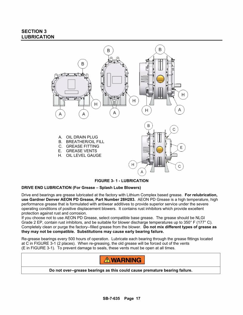
FIGURE 3- 1 - LUBRICATION
DRIVE END LUBRICATION (For Grease – Splash Lube Blowers)
Drive end bearings are grease lubricated at the factory with Lithium Complex based grease. For relubrication, use Gardner Denver AEON PD Grease, Part Number 28H283. AEON PD Grease is a high temperature, high performance grease that is formulated with antiwear additives to provide superior service under the severe operating conditions of positive displacement blowers. It contains rust inhibitors which provide excellent protection against rust and corrosion. If you choose not to use AEON PD Grease, select compatible base grease. The grease should be NLGI Grade 2 EP, contain rust inhibitors, and be suitable for blower discharge temperatures up to 350° F (177° C). Completely clean or purge the factory--filled grease from the blower. Do not mix different types of grease as they may not be compatible. Substitutions may cause early bearing failure.
Re-grease bearings every 500 hours of operation. Lubricate each bearing through the grease fittings located at C in FIGURE 3-1 (2 places). When re-greasing, the old grease will be forced out of the vents (E in FIGURE 3-1). To prevent damage to seals, these vents must be open at all times.
Do not over--grease bearings as this could cause premature bearing failure.
A. OIL DRAIN PLUG B. BREATHER/OIL FILL C. GREASE FITTING E. GREASE VENTS H. OIL LEVEL GAUGE
SB-7-635 Page 18
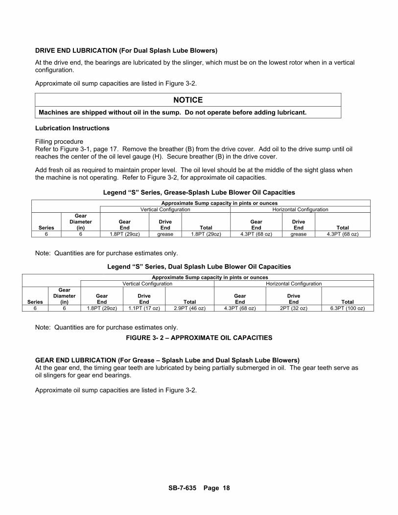
DRIVE END LUBRICATION (For Dual Splash Lube Blowers)
At the drive end, the bearings are lubricated by the slinger, which must be on the lowest rotor when in a vertical configuration. Approximate oil sump capacities are listed in Figure 3-2.
NOTICE
Machines are shipped without oil in the sump. Do not operate before adding lubricant. Lubrication Instructions Filling procedure Refer to Figure 3-1, page 17. Remove the breather (B) from the drive cover. Add oil to the drive sump until oil reaches the center of the oil level gauge (H). Secure breather (B) in the drive cover. Add fresh oil as required to maintain proper level. The oil level should be at the middle of the sight glass when the machine is not operating. Refer to Figure 3-2, for approximate oil capacities.
Legend “S” Series, Grease-Splash Lube Blower Oil Capacities
Approximate Sump capacity in pints or ounces Vertical Configuration Horizontal Configuration
Series
Gear Diameter
(in) Gear End
Drive End Total
Gear End
Drive End Total
6 6 1.8PT (29oz) grease 1.8PT (29oz) 4.3PT (68 oz) grease 4.3PT (68 oz)
Note: Quantities are for purchase estimates only.
Legend “S” Series, Dual Splash Lube Blower Oil Capacities
Approximate Sump capacity in pints or ounces Vertical Configuration Horizontal Configuration
Series
Gear Diameter
(in) Gear End
Drive End Total
Gear End
Drive End Total
6 6 1.8PT (29oz) 1.1PT (17 oz) 2.9PT (46 oz) 4.3PT (68 oz) 2PT (32 oz) 6.3PT (100 oz) Note: Quantities are for purchase estimates only.
FIGURE 3- 2 – APPROXIMATE OIL CAPACITIES
GEAR END LUBRICATION (For Grease – Splash Lube and Dual Splash Lube Blowers) At the gear end, the timing gear teeth are lubricated by being partially submerged in oil. The gear teeth serve as oil slingers for gear end bearings. Approximate oil sump capacities are listed in Figure 3-2.
SB-7-635 Page 19
Do not overfill as this will tend to cause excessive heating of the gears and may damage the unit.
NOTICE
Machines are shipped without oil in the sump. Do not operate before adding lubricant.
LUBRICATION INSTRUCTIONS Filling procedure Refer to FIGURE 3-1, page 17. Remove the breather (B) from the gear cover. Add oil to the gear case until oil reaches the center of the oil level gauge (H). Secure breather (B) in the gear cover. Add fresh oil as required to maintain proper level. The oil level should be at the middle of the sight glass when the machine is not operating. Refer to Figure 3-2, page 18, for approximate oil capacities.
SB-7-635 Page 20
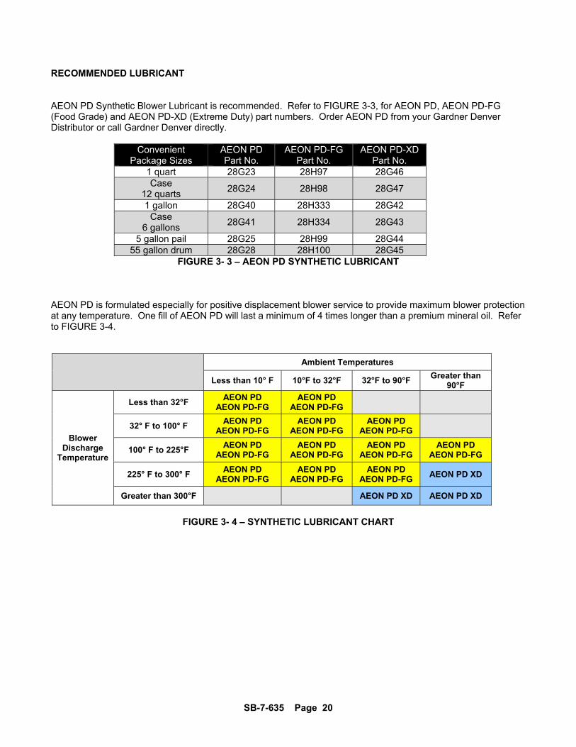
RECOMMENDED LUBRICANT AEON PD Synthetic Blower Lubricant is recommended. Refer to FIGURE 3-3, for AEON PD, AEON PD-FG (Food Grade) and AEON PD-XD (Extreme Duty) part numbers. Order AEON PD from your Gardner Denver Distributor or call Gardner Denver directly.
Convenient Package Sizes
AEON PD Part No.
AEON PD-FG Part No.
AEON PD-XD Part No.
1 quart 28G23 28H97 28G46 Case
12 quarts 28G24 28H98 28G47
1 gallon 28G40 28H333 28G42 Case
6 gallons 28G41 28H334 28G43
5 gallon pail 28G25 28H99 28G44 55 gallon drum 28G28 28H100 28G45
FIGURE 3- 3 – AEON PD SYNTHETIC LUBRICANT AEON PD is formulated especially for positive displacement blower service to provide maximum blower protection at any temperature. One fill of AEON PD will last a minimum of 4 times longer than a premium mineral oil. Refer to FIGURE 3-4.
Ambient Temperatures
Less than 10° F 10°F to 32°F 32°F to 90°F Greater than
90°F
Blower Discharge
Temperature
Less than 32°F AEON PD
AEON PD-FG AEON PD
AEON PD-FG
32° F to 100° F AEON PD
AEON PD-FG AEON PD
AEON PD-FG AEON PD
AEON PD-FG
100° F to 225°F AEON PD
AEON PD-FG AEON PD
AEON PD-FG AEON PD
AEON PD-FG AEON PD
AEON PD-FG
225° F to 300° F AEON PD
AEON PD-FG AEON PD
AEON PD-FG AEON PD
AEON PD-FG AEON PD XD
Greater than 300°F AEON PD XD AEON PD XD
FIGURE 3- 4 – SYNTHETIC LUBRICANT CHART
SB-7-635 Page 21
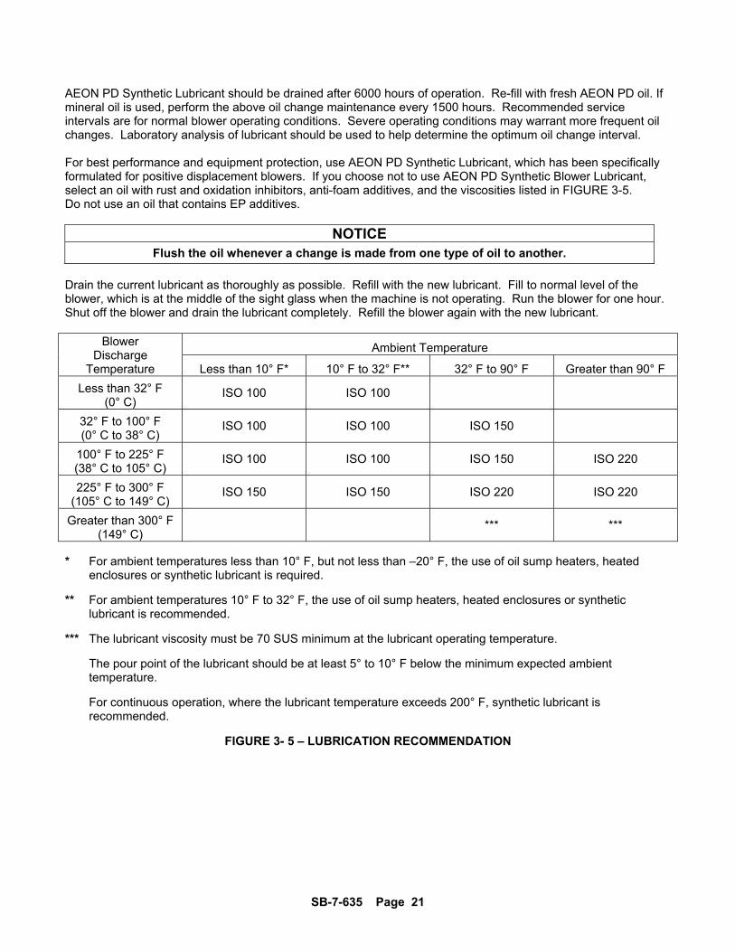
AEON PD Synthetic Lubricant should be drained after 6000 hours of operation. Re-fill with fresh AEON PD oil. If mineral oil is used, perform the above oil change maintenance every 1500 hours. Recommended service intervals are for normal blower operating conditions. Severe operating conditions may warrant more frequent oil changes. Laboratory analysis of lubricant should be used to help determine the optimum oil change interval. For best performance and equipment protection, use AEON PD Synthetic Lubricant, which has been specifically formulated for positive displacement blowers. If you choose not to use AEON PD Synthetic Blower Lubricant, select an oil with rust and oxidation inhibitors, anti-foam additives, and the viscosities listed in FIGURE 3-5. Do not use an oil that contains EP additives.
NOTICE Flush the oil whenever a change is made from one type of oil to another.
Drain the current lubricant as thoroughly as possible. Refill with the new lubricant. Fill to normal level of the blower, which is at the middle of the sight glass when the machine is not operating. Run the blower for one hour. Shut off the blower and drain the lubricant completely. Refill the blower again with the new lubricant.
Blower Discharge
Temperature
Ambient Temperature
Less than 10° F* 10° F to 32° F** 32° F to 90° F Greater than 90° F
Less than 32° F (0° C)
ISO 100 ISO 100
32° F to 100° F (0° C to 38° C)
ISO 100 ISO 100 ISO 150
100° F to 225° F (38° C to 105° C)
ISO 100 ISO 100 ISO 150 ISO 220
225° F to 300° F (105° C to 149° C)
ISO 150 ISO 150 ISO 220 ISO 220
Greater than 300° F (149° C)
*** ***
* For ambient temperatures less than 10° F, but not less than –20° F, the use of oil sump heaters, heated enclosures or synthetic lubricant is required. ** For ambient temperatures 10° F to 32° F, the use of oil sump heaters, heated enclosures or synthetic lubricant is recommended. *** The lubricant viscosity must be 70 SUS minimum at the lubricant operating temperature. The pour point of the lubricant should be at least 5° to 10° F below the minimum expected ambient temperature. For continuous operation, where the lubricant temperature exceeds 200° F, synthetic lubricant is recommended.
FIGURE 3- 5 – LUBRICATION RECOMMENDATION
SB-7-635 Page 22
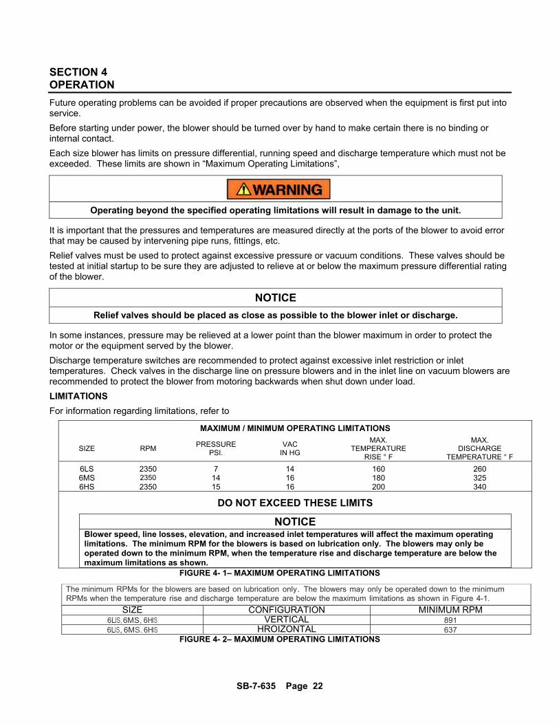
SECTION 4 OPERATION
Future operating problems can be avoided if proper precautions are observed when the equipment is first put into service.
Before starting under power, the blower should be turned over by hand to make certain there is no binding or internal contact.
Each size blower has limits on pressure differential, running speed and discharge temperature which must not be exceeded. These limits are shown in “Maximum Operating Limitations”,
Operating beyond the specified operating limitations will result in damage to the unit.
It is important that the pressures and temperatures are measured directly at the ports of the blower to avoid error that may be caused by intervening pipe runs, fittings, etc.
Relief valves must be used to protect against excessive pressure or vacuum conditions. These valves should be tested at initial startup to be sure they are adjusted to relieve at or below the maximum pressure differential rating of the blower.
NOTICE
Relief valves should be placed as close as possible to the blower inlet or discharge.
In some instances, pressure may be relieved at a lower point than the blower maximum in order to protect the motor or the equipment served by the blower.
Discharge temperature switches are recommended to protect against excessive inlet restriction or inlet temperatures. Check valves in the discharge line on pressure blowers and in the inlet line on vacuum blowers are recommended to protect the blower from motoring backwards when shut down under load.
LIMITATIONS
For information regarding limitations, refer to
MAXIMUM / MINIMUM OPERATING LIMITATIONS
SIZE RPM PRESSURE
PSI. VAC
IN HG
MAX. TEMPERATURE
RISE ° F
MAX. DISCHARGE
TEMPERATURE ° F
6LS 2350 7 14 160 260 6MS 2350 14 16 180 325 6HS 2350 15 16 200 340
DO NOT EXCEED THESE LIMITS
NOTICE Blower speed, line losses, elevation, and increased inlet temperatures will affect the maximum operating limitations. The minimum RPM for the blowers is based on lubrication only. The blowers may only be operated down to the minimum RPM, when the temperature rise and discharge temperature are below the maximum limitations as shown.
FIGURE 4- 1– MAXIMUM OPERATING LIMITATIONS
The minimum RPMs for the blowers are based on lubrication only. The blowers may only be operated down to the minimum RPMs when the temperature rise and discharge temperature are below the maximum limitations as shown in Figure 4-1.
SIZE CONFIGURATION MINIMUM RPM6LIS, 6MS, 6HIS VERTICAL 8916LIS, 6MS. 6HIS HROIZONTAL 637
FIGURE 4- 2– MAXIMUM OPERATING LIMITATIONS

SB-7-635 Page 23
BLOWER STARTUP CHECKLIST
This startup procedure should be followed during the initial installation and after any shutdown periods or after the blower has been worked on or moved to new location. It is suggested that the steps be followed in sequence and checked off (√) in the boxes provided.
1. Check the unit and all piping for foreign material and clean if required.
2. Check the flatness of the feet and the alignment of the drive. Feet that are bolted down in a bind can cause housing distortion and internal rubbing. Misaligned V-drives can cause the rotors to rub against the headplates and cause a reduction in the volumetric efficiency of the unit. Misaligned couplings can ruin bearings.
3. If the blower is V-belt driven, check the belt tension and alignment. Over-tensioned belts create
heavy bearing/shaft loads which lead to premature failure.
4. Be sure adequate drive guards are in place to protect the operator from severe personal injury and incidental contact.
5. Check the unit for proper lubrication. Proper oil level cannot be over-emphasized. Too little oil
will ruin bearings and gears. Too much oil will cause overheating and can ruin gears and cause other damage. Insure that grease lubricated bearings are properly lubricated.
6. With motor electrical power locked out and disconnected, turn the drive shaft by hand to be
certain the impellers do not bind.
7. “Jog” the unit with the motor a few times to check that rotation is in the proper direction, and to be certain it turns freely and smoothly.
8. The internal surfaces of all Sutorbilt units are mist sprayed with a rust preventive to protect the
machine during the shipping and installation period. This film should be removed upon initial startup.
9. Start the unit and operate 15 minutes at no load. During this time, check for hot spots and other
indications of interference.
10. Apply the load and observe the operation of the unit for one hour. Check frequently during the first day of operation.
11. If malfunctions occur, do not continue to operate. Problems such as knocking rotors can cause
serious damage if the unit is operated without correction.
SB-7-635 Page 24
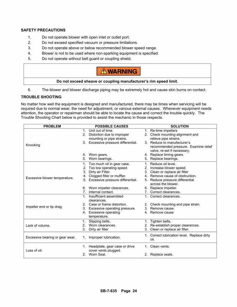
SAFETY PRECAUTIONS
1. Do not operate blower with open inlet or outlet port.
2. Do not exceed specified vacuum or pressure limitations.
3. Do not operate above or below recommended blower speed range.
4. Blower is not to be used where non-sparking equipment is specified.
5. Do not operate without belt guard or coupling shield.
Do not exceed sheave or coupling manufacturer’s rim speed limit.
6. The blower and blower discharge piping may be extremely hot and cause skin burns on contact.
TROUBLE SHOOTING
No matter how well the equipment is designed and manufactured, there may be times when servicing will be required due to normal wear, the need for adjustment, or various external causes. Whenever equipment needs attention, the operator or repairman should be able to locate the cause and correct the trouble quickly. The Trouble Shooting Chart below is provided to assist the mechanic in those respects.
PROBLEM POSSIBLE CAUSES SOLUTION
Knocking
1. Unit out of time. 2. Distortion due to improper mounting or pipe strains. 3. Excessive pressure differential. 4. Worn gears. 5. Worn bearings.
1. Re-time impellers 2. Check mounting alignment and relieve pipe strains. 3. Reduce to manufacturer’s recommended pressure. Examine relief valve, re-set if necessary. 4. Replace timing gears. 5. Replace bearings.
Excessive blower temperature.
1. Too much oil in gear case. 2. Too low operating speed. 3. Dirty air Filter. 4. Clogged filter or muffler. 5. Excessive pressure differential. 6. Worn impeller clearances. 7. Internal contact.
1. Reduce oil level. 2. Increase blower speed. 3. Clean or replace air filter 4. Remove cause of obstruction. 5. Reduce pressure differential across the blower. 6. Replace impeller. 7. Correct clearances.
Impeller end or tip drag.
1. Insufficient assembled clearances. 2. Case or frame distortion. 3. Excessive operating pressure. 4. Excessive operating temperature.
1. Correct clearances. 2. Check mounting and pipe strain. 3. Remove cause. 4. Remove cause
Lack of volume. 1. Slipping belts. 2. Worn clearances. 3. Dirty air filter
1. Tighten belts. 2. Re-establish proper clearances. 3. Clean or replace air filter.
Excessive bearing or gear wear. 1. Improper lubrication. 1. Correct lubrication level. Replace dirty oil.
Loss of oil. 1. Headplate, gear case or drive cover vents plugged. 2. Worn Seal.
1. Clean vents. 2. Replace seals.
SB-7-635 Page 25
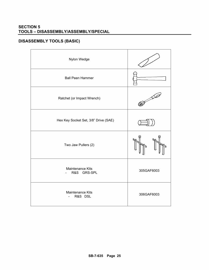
SECTION 5 TOOLS – DISASSEMBLY/ASSEMBLY/SPECIAL DISASSEMBLY TOOLS (BASIC)
Nylon Wedge
Ball Peen Hammer
Ratchet (or Impact Wrench)
Hex Key Socket Set, 3/8” Drive (SAE)
Two Jaw Pullers (2)
Maintenance Kits - R&S GRS-SPL
305GAF6003
Maintenance Kits - R&S DSL
306GAF6003
SB-7-635 Page 26
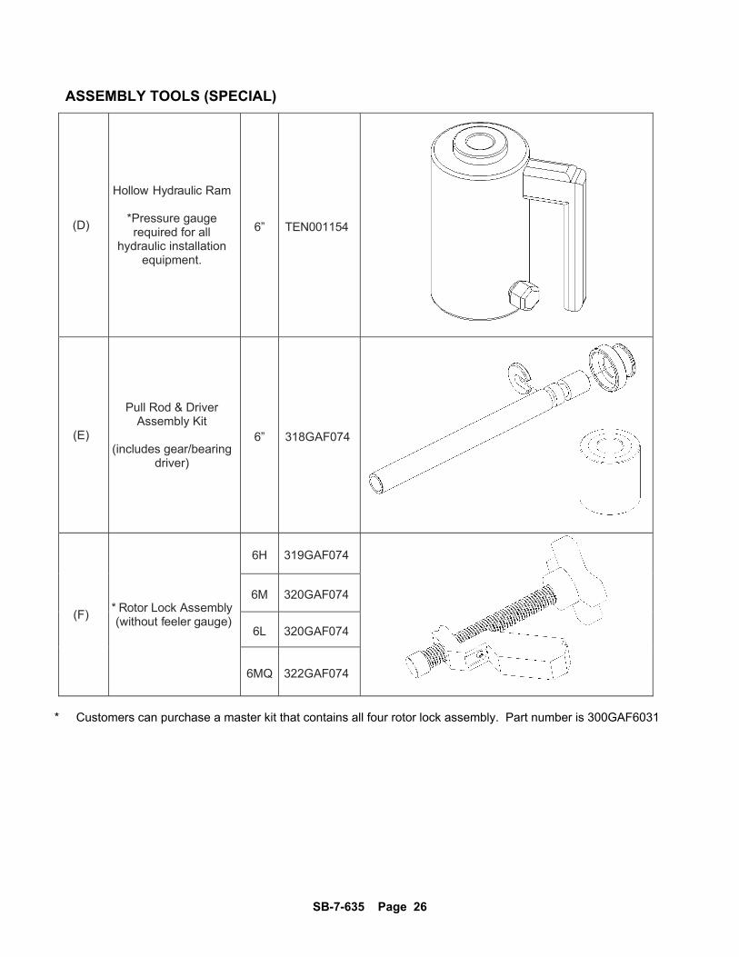
ASSEMBLY TOOLS (SPECIAL)
(D)
Hollow Hydraulic Ram
*Pressure gauge required for all
hydraulic installation equipment.
6” TEN001154
(E)
Pull Rod & Driver Assembly Kit
(includes gear/bearing
driver)
6” 318GAF074
(F) * Rotor Lock Assembly (without feeler gauge)
6H 319GAF074
6M 320GAF074
6L 320GAF074
6MQ 322GAF074
* Customers can purchase a master kit that contains all four rotor lock assembly. Part number is 300GAF6031
SB-7-635 Page 27
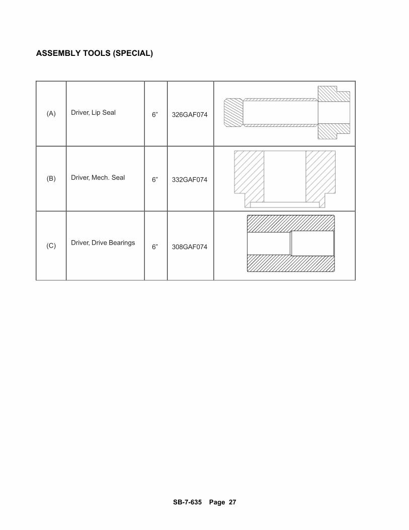
ASSEMBLY TOOLS (SPECIAL)
(A)
Driver, Lip Seal 6” 326GAF074
(B)
Driver, Mech. Seal 6” 332GAF074
(C)
Driver, Drive Bearings 6” 308GAF074
SB-7-635 Page 28
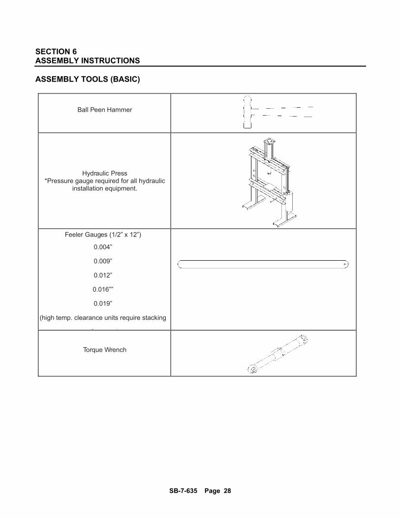
SECTION 6 ASSEMBLY INSTRUCTIONS
ASSEMBLY TOOLS (BASIC)
Ball Peen Hammer
Hydraulic Press *Pressure gauge required for all hydraulic
installation equipment.
Feeler Gauges (1/2” x 12”)
0.004”
0.009”
0.012”
0.016””
0.019”
(high temp. clearance units require stacking
f )
Torque Wrench
SB-7-635 Page 29
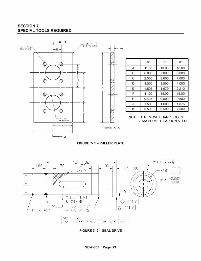
SECTION 7 SPECIAL TOOLS REQUIRED
FIGURE 7- 1 – PULLER PLATE
FIGURE 7- 2 – SEAL DRIVE
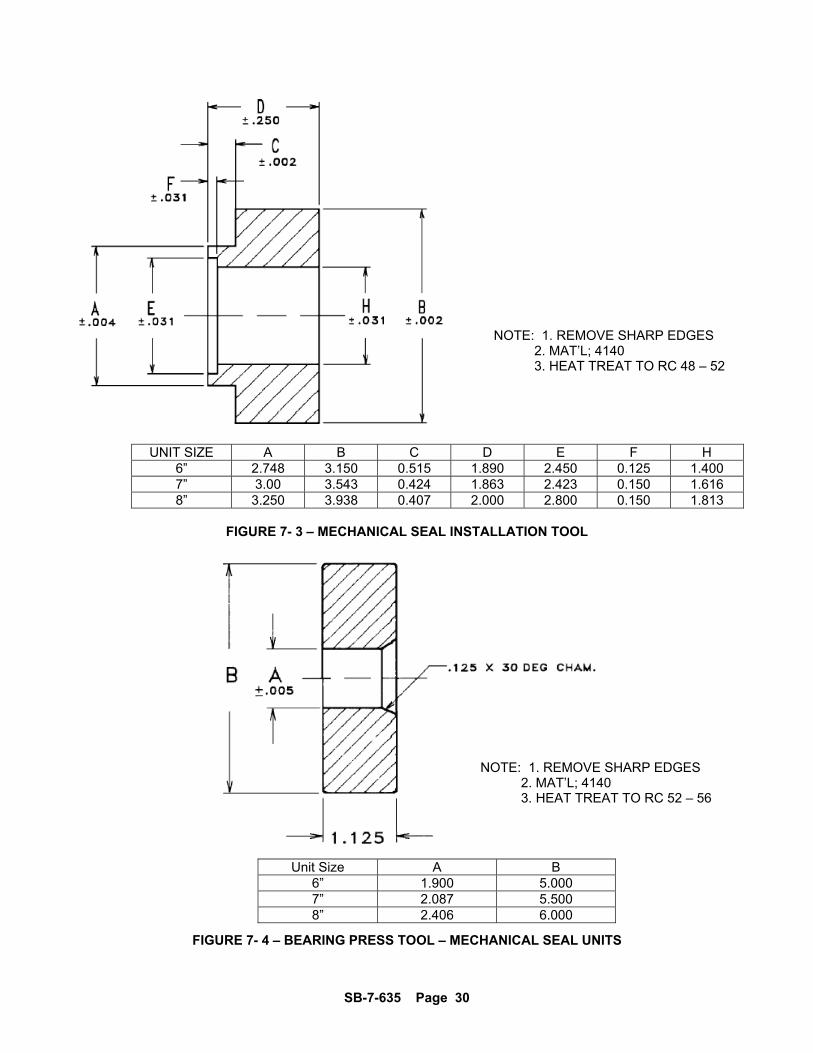
NOTE: 1. REMOVE SHARP EDGES 2. MAT’L; MED. CARBON STEEL
SB-7-635 Page 30
UNIT SIZE A B C D E F H 6” 2.748 3.150 0.515 1.890 2.450 0.125 1.400 7” 3.00 3.543 0.424 1.863 2.423 0.150 1.616 8” 3.250 3.938 0.407 2.000 2.800 0.150 1.813
FIGURE 7- 3 – MECHANICAL SEAL INSTALLATION TOOL
Unit Size A B 6” 1.900 5.000 7” 2.087 5.500 8” 2.406 6.000
FIGURE 7- 4 – BEARING PRESS TOOL – MECHANICAL SEAL UNITS
NOTE: 1. REMOVE SHARP EDGES 2. MAT’L; 4140 3. HEAT TREAT TO RC 48 – 52
NOTE: 1. REMOVE SHARP EDGES 2. MAT’L; 4140 3. HEAT TREAT TO RC 52 – 56

SB-7-635 Page 31
7- 1 – Gear Cover Removal • Drain oil by removing plug (2) from gear end cover (3). • NOTE – For DSL units, repeat previous step to drain oil on drive end. • Remove gear cover (3) by removing screws (30). 7- 2 – Flange Nut Removal • Place a nylon wedge or shop rag between gears to stop rotation while removing flange nuts. • Remove flange nuts (89).
SB-7-635 Page 32
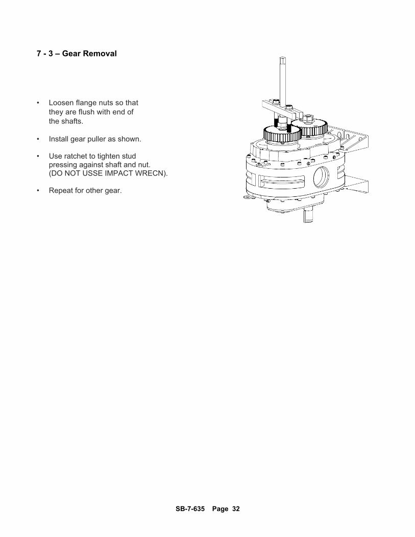
7 - 3 – Gear Removal • Loosen flange nuts so that they are flush with end of the shafts. • Install gear puller as shown. • Use ratchet to tighten stud pressing against shaft and nut. (DO NOT USSE IMPACT WRECN). • Repeat for other gear.
SB-7-635 Page 33
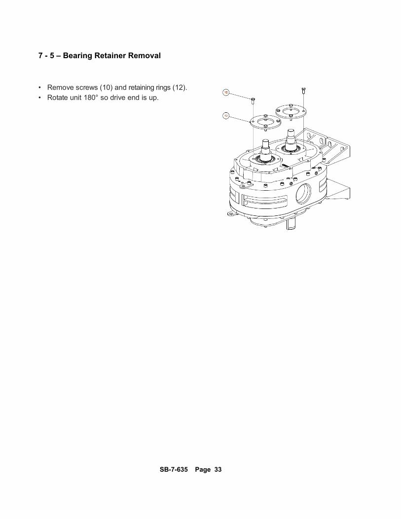
7 - 5 – Bearing Retainer Removal • Remove screws (10) and retaining rings (12).
• Rotate unit 180° so drive end is up.
SB-7-635 Page 34
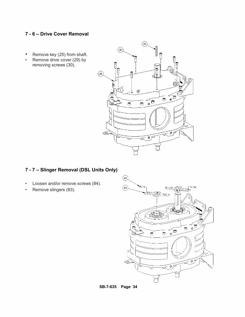
7 - 6 – Drive Cover Removal • Remove key (25) from shaft. • Remove drive cover (29) by removing screws (30). 7 - 7 – Slinger Removal (DSL Units Only) • Loosen and/or remove screws (84).
• Remove slingers (83).

SB-7-635 Page 35
7- 8 – Foot and Lifting Lug Removal (Drive End)
• Remove lifting lug (20) and foot (17)
by removing screws (21) and (16) respectively. • Remove remaining screws (21).
• Remove dowel pins from bearing housing. 7- 9 – Puller Plate Installation • Install puller plate (J) as shown.
SB-7-635 Page 36
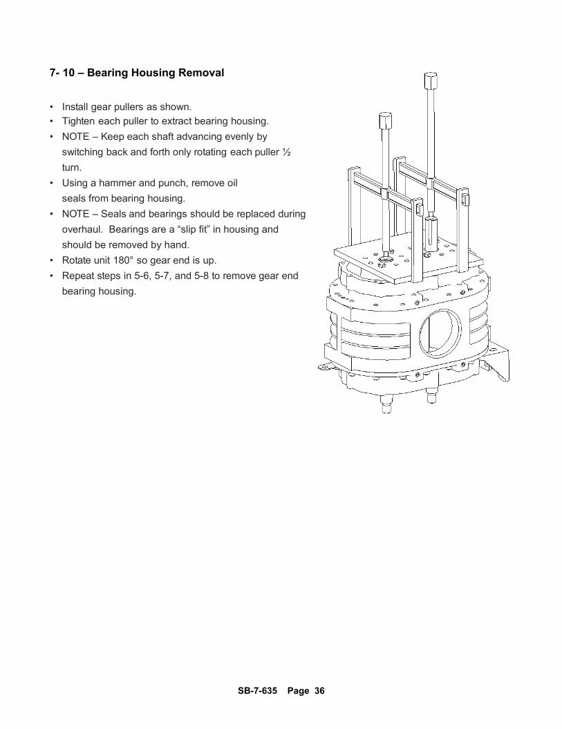
7- 10 – Bearing Housing Removal • Install gear pullers as shown.
• Tighten each puller to extract bearing housing.
• NOTE – Keep each shaft advancing evenly by
switching back and forth only rotating each puller ½
turn.
• Using a hammer and punch, remove oil
seals from bearing housing.
• NOTE – Seals and bearings should be replaced during
overhaul. Bearings are a “slip fit” in housing and
should be removed by hand.
• Rotate unit 180° so gear end is up.
• Repeat steps in 5-6, 5-7, and 5-8 to remove gear end
bearing housing.
SB-7-635 Page 37
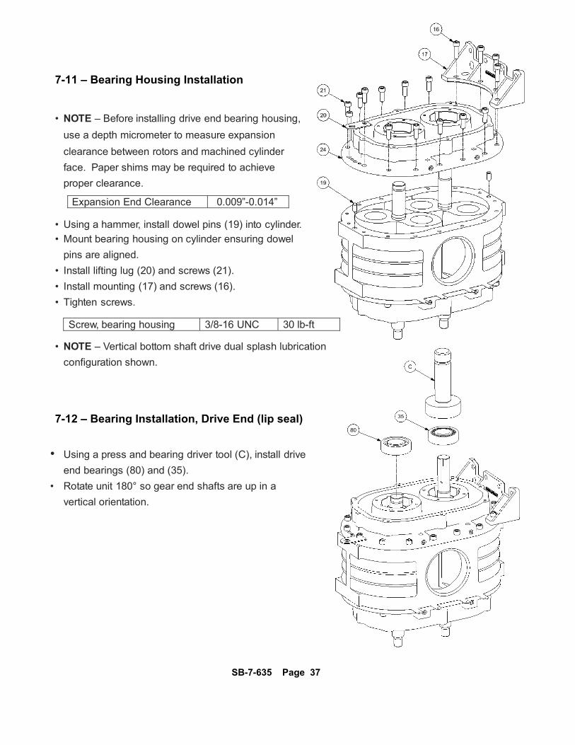
7-11 – Bearing Housing Installation
• NOTE – Before installing drive end bearing housing,
use a depth micrometer to measure expansion
clearance between rotors and machined cylinder
face. Paper shims may be required to achieve
proper clearance.
Expansion End Clearance 0.009”-0.014” • Using a hammer, install dowel pins (19) into cylinder.
• Mount bearing housing on cylinder ensuring dowel
pins are aligned.
• Install lifting lug (20) and screws (21).
• Install mounting (17) and screws (16).
• Tighten screws.
Screw, bearing housing 3/8-16 UNC 30 lb-ft • NOTE – Vertical bottom shaft drive dual splash lubrication
configuration shown. 7-12 – Bearing Installation, Drive End (lip seal)
• Using a press and bearing driver tool (C), install drive
end bearings (80) and (35).
• Rotate unit 180° so gear end shafts are up in a
vertical orientation.
SB-7-635 Page 38
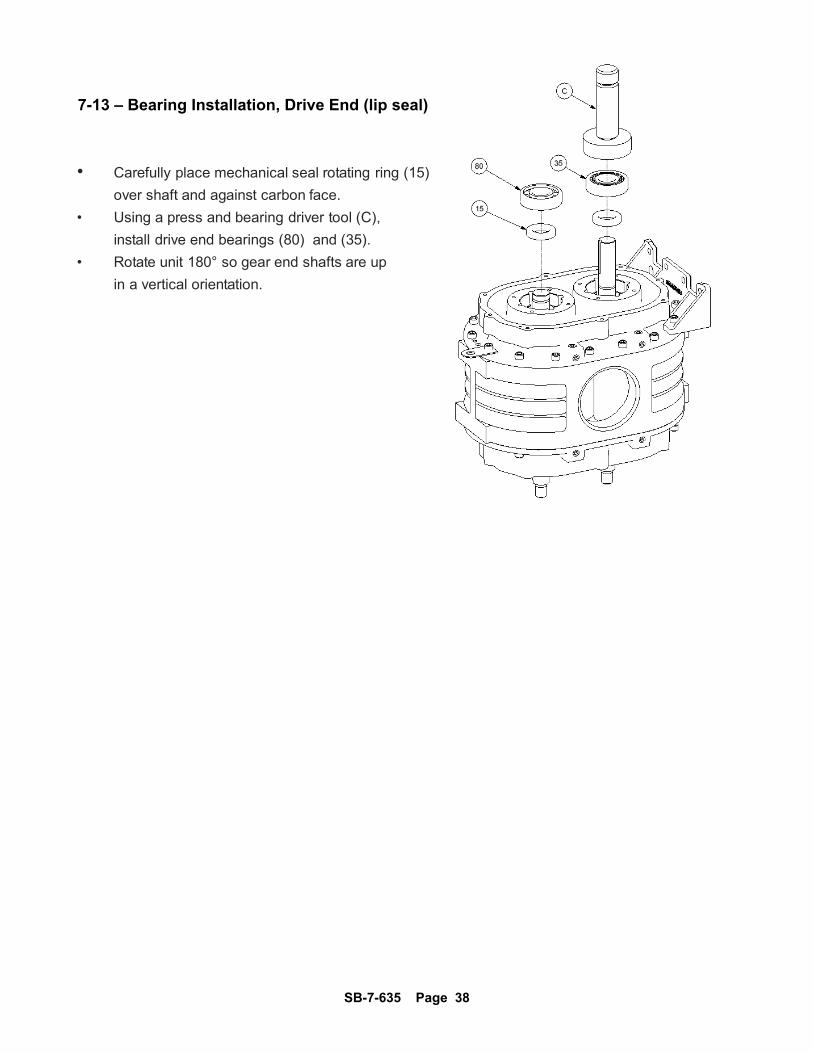
7-13 – Bearing Installation, Drive End (lip seal)
• Carefully place mechanical seal rotating ring (15)
over shaft and against carbon face.
• Using a press and bearing driver tool (C),
install drive end bearings (80) and (35).
• Rotate unit 180° so gear end shafts are up
in a vertical orientation.
SB-7-635 Page 39
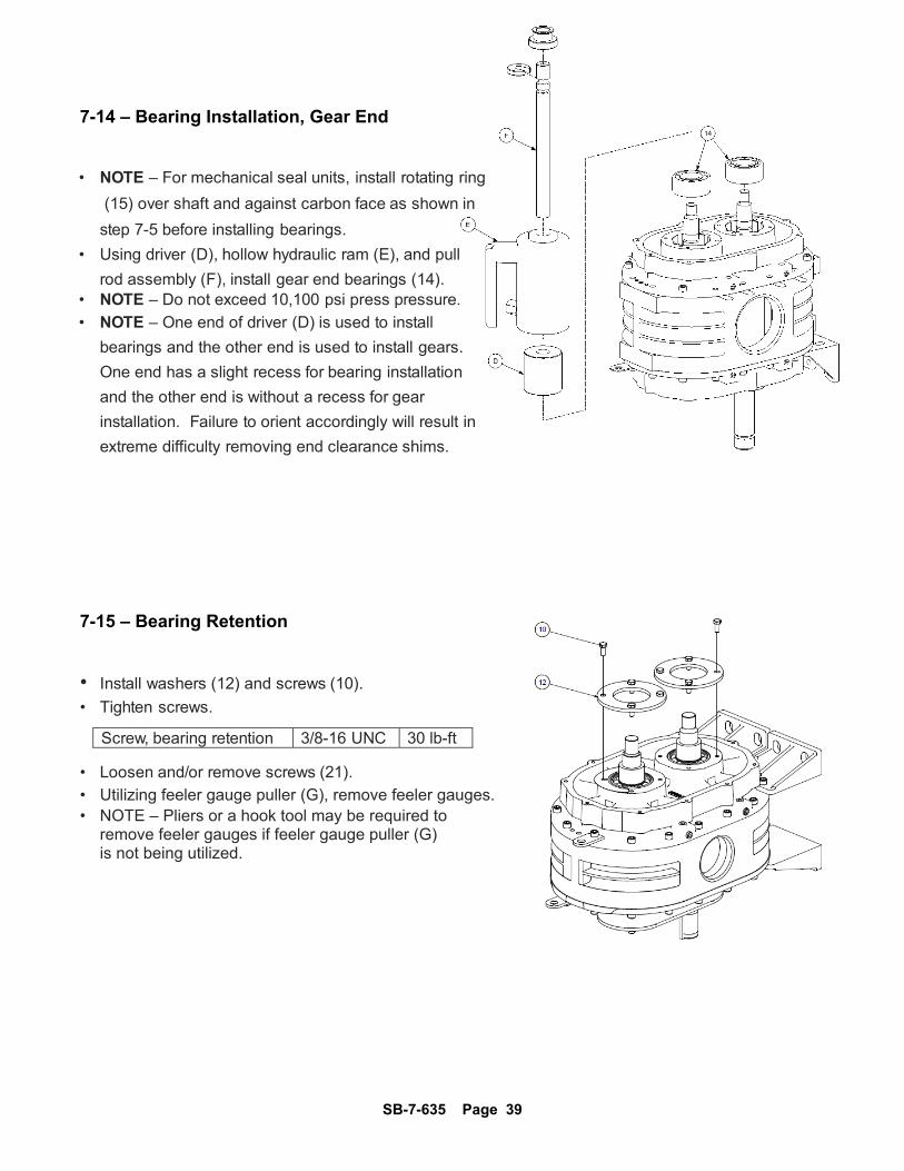
7-14 – Bearing Installation, Gear End • NOTE – For mechanical seal units, install rotating ring
(15) over shaft and against carbon face as shown in
step 7-5 before installing bearings.
• Using driver (D), hollow hydraulic ram (E), and pull
rod assembly (F), install gear end bearings (14). • NOTE – Do not exceed 10,100 psi press pressure.
• NOTE – One end of driver (D) is used to install
bearings and the other end is used to install gears.
One end has a slight recess for bearing installation
and the other end is without a recess for gear
installation. Failure to orient accordingly will result in
extreme difficulty removing end clearance shims. 7-15 – Bearing Retention • Install washers (12) and screws (10).
• Tighten screws.
Screw, bearing retention 3/8-16 UNC 30 lb-ft • Loosen and/or remove screws (21).
• Utilizing feeler gauge puller (G), remove feeler gauges. • NOTE – Pliers or a hook tool may be required to remove feeler gauges if feeler gauge puller (G) is not being utilized.
SB-7-635 Page 40
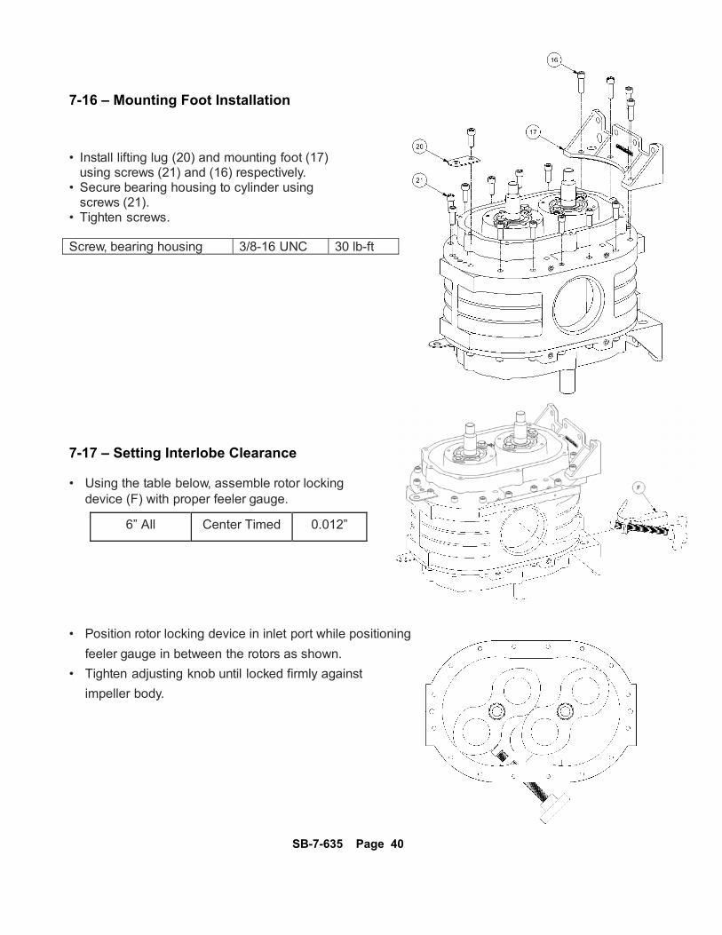
7-16 – Mounting Foot Installation • Install lifting lug (20) and mounting foot (17) using screws (21) and (16) respectively. • Secure bearing housing to cylinder using screws (21). • Tighten screws. Screw, bearing housing 3/8-16 UNC 30 lb-ft 7-17 – Setting Interlobe Clearance • Using the table below, assemble rotor locking device (F) with proper feeler gauge.
6” All Center Timed 0.012”
• Position rotor locking device in inlet port while positioning
feeler gauge in between the rotors as shown.
• Tighten adjusting knob until locked firmly against
impeller body.
SB-7-635 Page 41
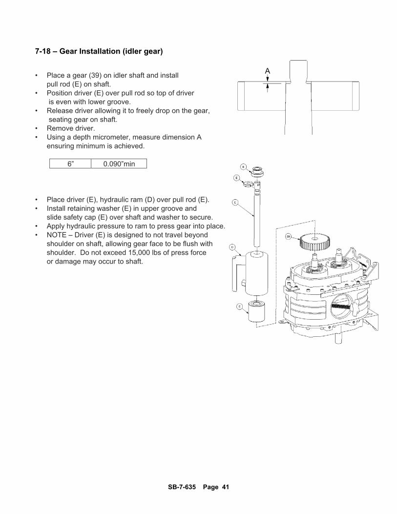
7-18 – Gear Installation (idler gear) • Place a gear (39) on idler shaft and install pull rod (E) on shaft. • Position driver (E) over pull rod so top of driver is even with lower groove. • Release driver allowing it to freely drop on the gear, seating gear on shaft. • Remove driver. • Using a depth micrometer, measure dimension A ensuring minimum is achieved.
6” 0.090”min • Place driver (E), hydraulic ram (D) over pull rod (E). • Install retaining washer (E) in upper groove and slide safety cap (E) over shaft and washer to secure. • Apply hydraulic pressure to ram to press gear into place. • NOTE – Driver (E) is designed to not travel beyond shoulder on shaft, allowing gear face to be flush with shoulder. Do not exceed 15,000 lbs of press force or damage may occur to shaft.

SB-7-635 Page 42
7-19 – Gear Installation (drive gear) • Place a gear (39) on drive shaft and install pull rod (E).
• Position driver (E) over pull rod so top of driver is even with lower groove.
•
• Rotate and hold gear in mesh against other gear in direction of operational rotation to remove backlash.
•
• Release driver allowing it to freely drop on the gear, seating gear on shaft. • Remove driver. • • Using a depth micrometer, measure dimension A ensuring minimum is achieved. NOTE: If min dimension is not achieved, gear and/or shaft may need replaced.
6” 0.090”min • Place driver (E), hydraulic ram (D) on pull rod (E) as shown.
•
• Install retaining washer (E) on upper groove and slide safety cap (E) over washer to secure.
•
• Apply hydraulic pressure to ram to press gear into place.
•
• NOTE – Driver (E) is designed to not travel beyond shoulder on shaft, allowing gear face to be flush with shoulder. Do not exceed 15,000 lbs of press force or damage may occur to shaft.

SB-7-635 Page 43
7-20 – Flange Nut Installation • Apply Loctite 243 to threads of flange nut (41) and Install on each shaft.
• Tighten nuts.
6” Nut, shaft 1-14 60 lb-ft
7-21 – Gear Cover Installation • Install O-ring (7) into gear cover (3). • Secure sump cover to bearing housing using screws (30). • Tighten screws.
Screw, gear cover 5/16-18 UNC 156 lb-in • Apply thread sealant to plugs (2), oil level gauge (40) and breather (6) and install according to unit configuration. • Tighten plugs, gauge, and breather.
Plugs, gauge, breather 1/2 NPT • Rotate unit 180° so drive end is facing up.

SB-7-635 Page 44
7- 22 – Seal Installation (lip seals)
• Ensure bearing housings are clean and free of any nicks and burrs.
• Apply grease or light oil to the inner and outer diameter of
each shaft seal (15) .
• Using a press and seal driver (A) , carefully install each seal
until fully seated. • Apply thread sealant to plugs (44).
• Tighten plugs.
6” Plug, air vent 1/2-13 UNC
• Repeat steps for other bearing housing. 7-23 – Seal Installation (mechanical seals) • Ensure bearing housings are clean and free of any nicks
and burrs. • Apply assembly lubricant to each seal bore.
• Using a press and seal driver (B), carefully install each
seal (cup and carbon assembly only) until fully seated.
• NOTE – Use extreme care when handling or installing
mechanical seals. Blows from a hammer can damage
the fragile seal surface. Too much force can crush the
seal casing. Ensure seal is fully seated and
undamaged before proceeding.
• Apply thread sealant to plugs (44) and (46).
• Tighten plugs.
6” Plug, air vent 1/2-13 UNC
• Repeat steps for the other bearing housing
SB-7-635 Page 45
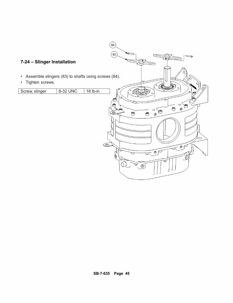
7-24 – Slinger Installation • Assemble slingers (83) to shafts using screws (84).
• Tighten screws. Screw, slinger 8-32 UNC 18 lb-in
SB-7-635 Page 46
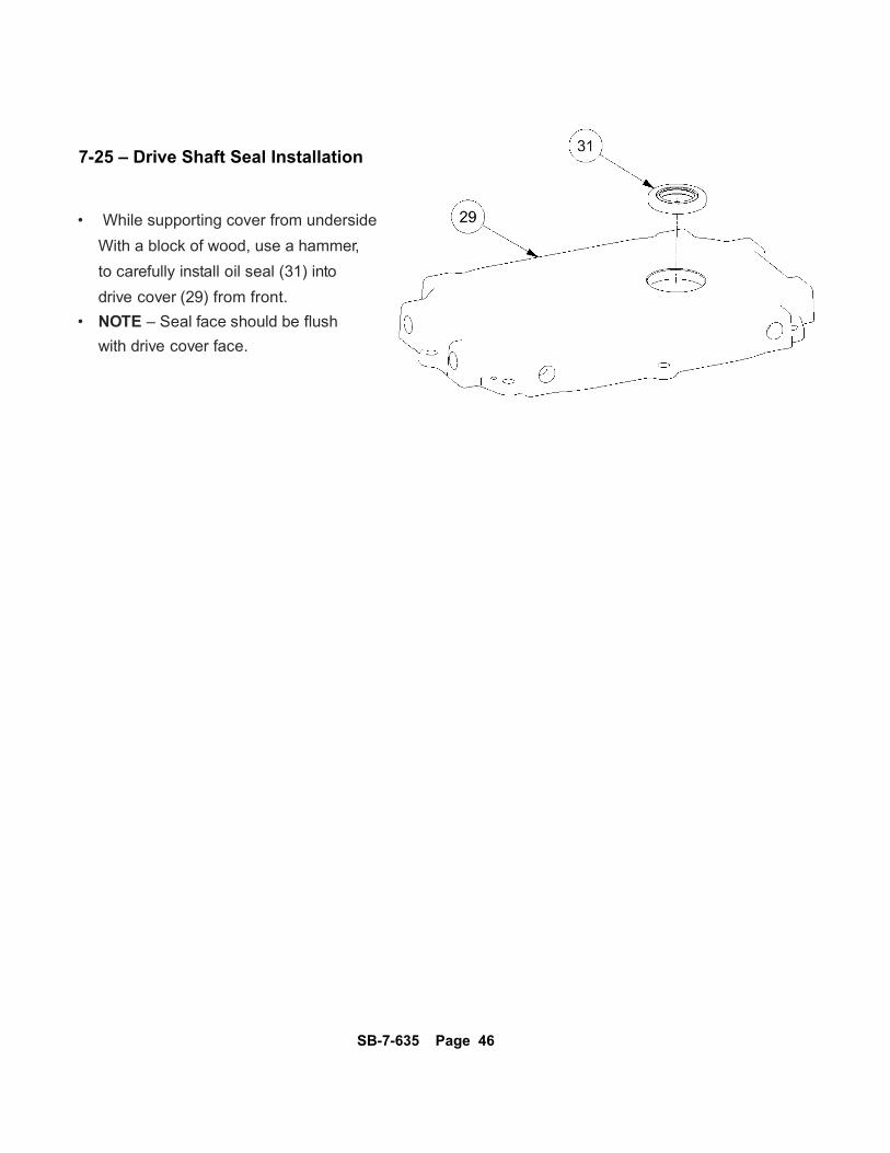
7-25 – Drive Shaft Seal Installation
• While supporting cover from underside
With a block of wood, use a hammer,
to carefully install oil seal (31) into
drive cover (29) from front.
• NOTE – Seal face should be flush
with drive cover face.
SB-7-635 Page 47
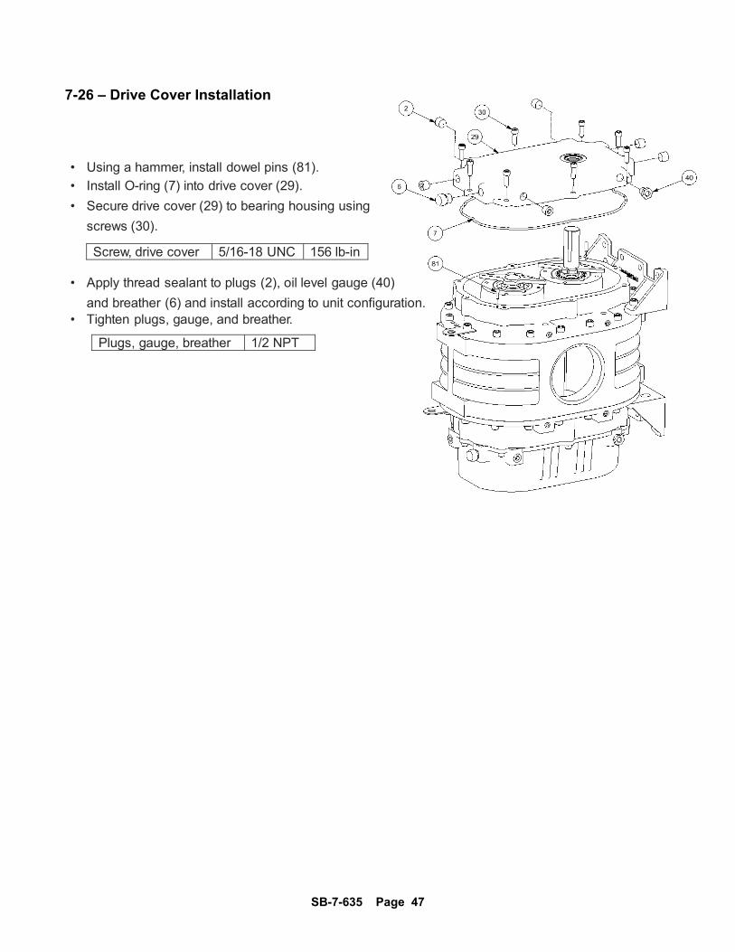
7-26 – Drive Cover Installation • Using a hammer, install dowel pins (81).
• Install O-ring (7) into drive cover (29).
• Secure drive cover (29) to bearing housing using
screws (30).
Screw, drive cover 5/16-18 UNC 156 lb-in • Apply thread sealant to plugs (2), oil level gauge (40)
and breather (6) and install according to unit configuration. • Tighten plugs, gauge, and breather.
Plugs, gauge, breather 1/2 NPT

SB-7-635 Page 48
7-27 – Cylinder Installation • Using a hammer, install dowel pins 19 into gear end bearing housing 18.
• Position four feeler gauges on bearing housing as shown.
Feeler Gauge 0.004” • NOTE – Feeler gauges are used to set the rotor end clearance. Ensure enough of the gauge is extended and accessible for removal.
• Mount cylinder 22 ensuring dowel pins are aligned. • Install four screws 21 to temporarily secure cylinder to bearing housing. • Tighten screws.
Screw, cylinder 3/8-16 UNC 30 lb-ft 7-28 – Rotor Installation • Insert rotors (23) into cylinder as shown. • NOTE – Use caution when installing rotors as misalignment can cause shaft to damage seals. • NOTE – For ‘Q’ cylinder models, ensure drive rotor position and rotation match configuration. Failure to do so will result in greatly reduced performance.
SB-7-635 Page 49
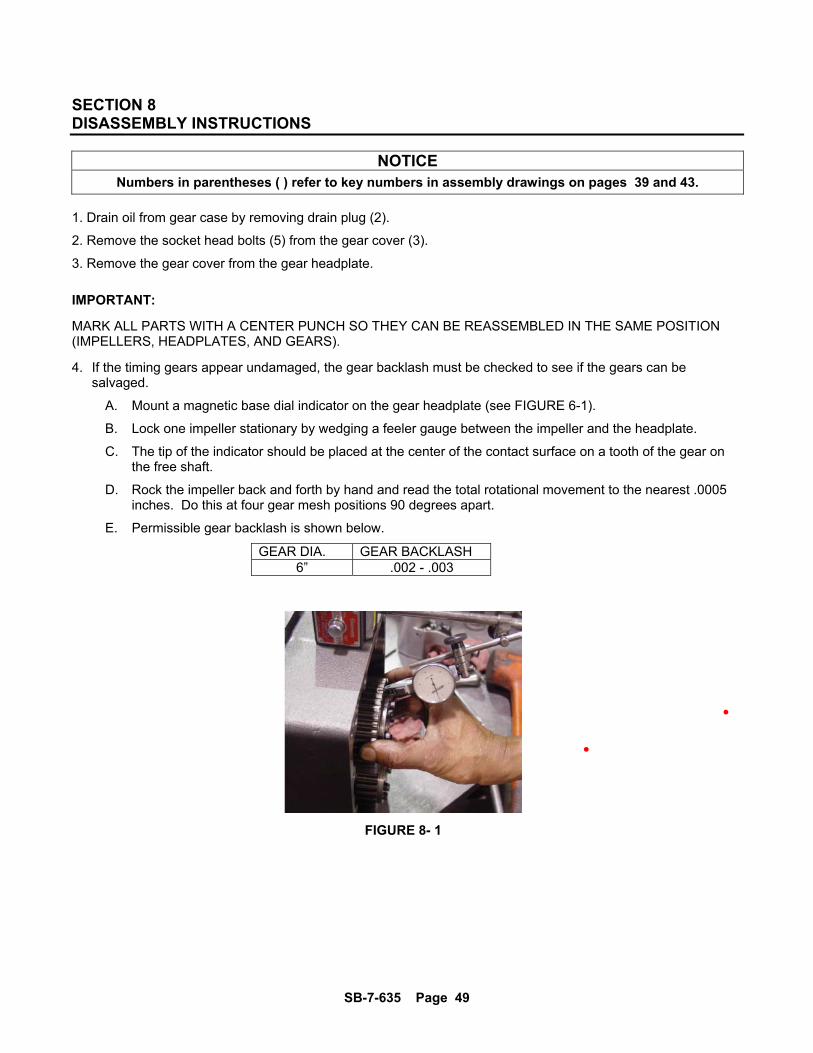
SECTION 8 DISASSEMBLY INSTRUCTIONS
NOTICE Numbers in parentheses ( ) refer to key numbers in assembly drawings on pages 39 and 43.
1. Drain oil from gear case by removing drain plug (2).
2. Remove the socket head bolts (5) from the gear cover (3).
3. Remove the gear cover from the gear headplate.
IMPORTANT:
MARK ALL PARTS WITH A CENTER PUNCH SO THEY CAN BE REASSEMBLED IN THE SAME POSITION (IMPELLERS, HEADPLATES, AND GEARS).
4. If the timing gears appear undamaged, the gear backlash must be checked to see if the gears can be salvaged.
A. Mount a magnetic base dial indicator on the gear headplate (see FIGURE 6-1).
B. Lock one impeller stationary by wedging a feeler gauge between the impeller and the headplate.
C. The tip of the indicator should be placed at the center of the contact surface on a tooth of the gear on the free shaft.
D. Rock the impeller back and forth by hand and read the total rotational movement to the nearest .0005 inches. Do this at four gear mesh positions 90 degrees apart.
E. Permissible gear backlash is shown below.
GEAR DIA. GEAR BACKLASH 6” .002 - .003
FIGURE 8- 1
SB-7-635 Page 50
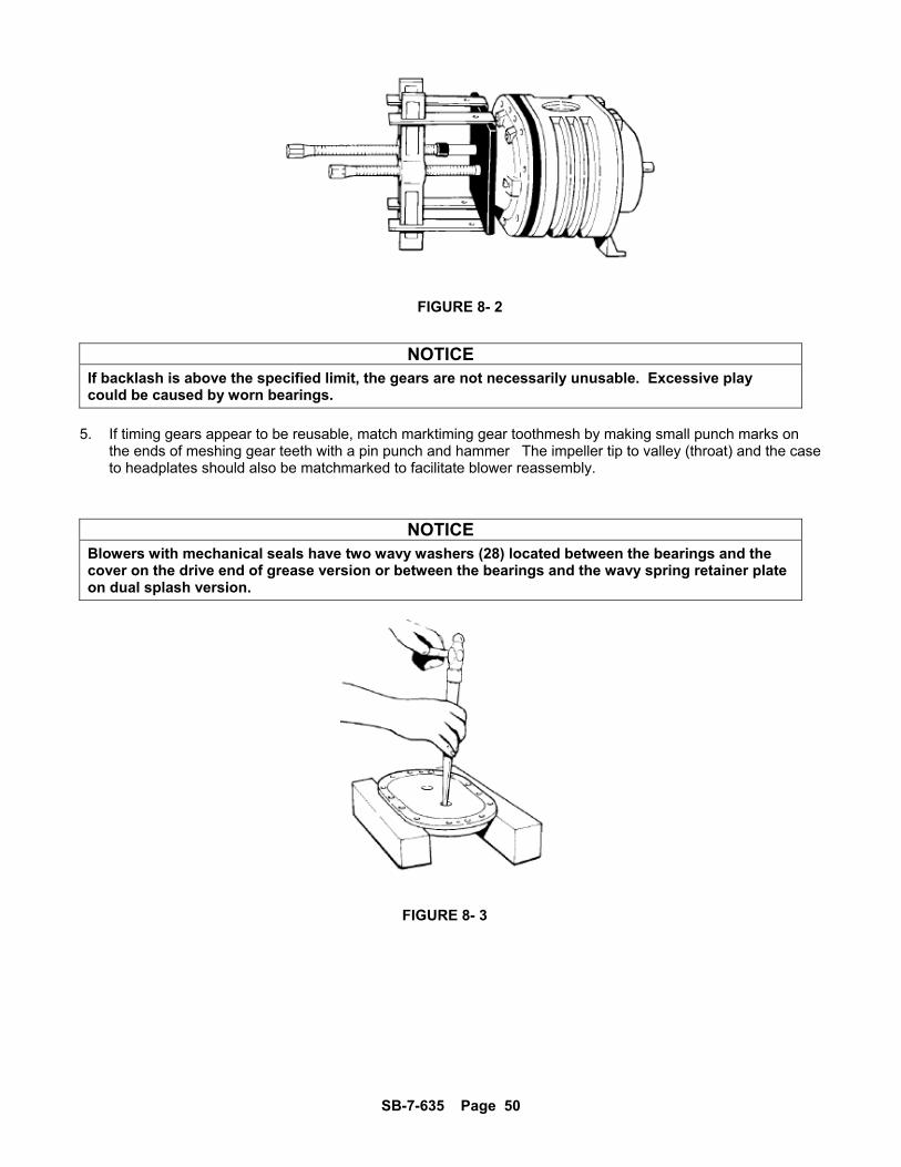
NOTICE If backlash is above the specified limit, the gears are not necessarily unusable. Excessive play could be caused by worn bearings.
5. If timing gears appear to be reusable, match marktiming gear toothmesh by making small punch marks on the ends of meshing gear teeth with a pin punch and hammer The impeller tip to valley (throat) and the case to headplates should also be matchmarked to facilitate blower reassembly.
NOTICE Blowers with mechanical seals have two wavy washers (28) located between the bearings and the cover on the drive end of grease version or between the bearings and the wavy spring retainer plate on dual splash version.
FIGURE 8- 2
FIGURE 8- 3
SB-7-635 Page 51
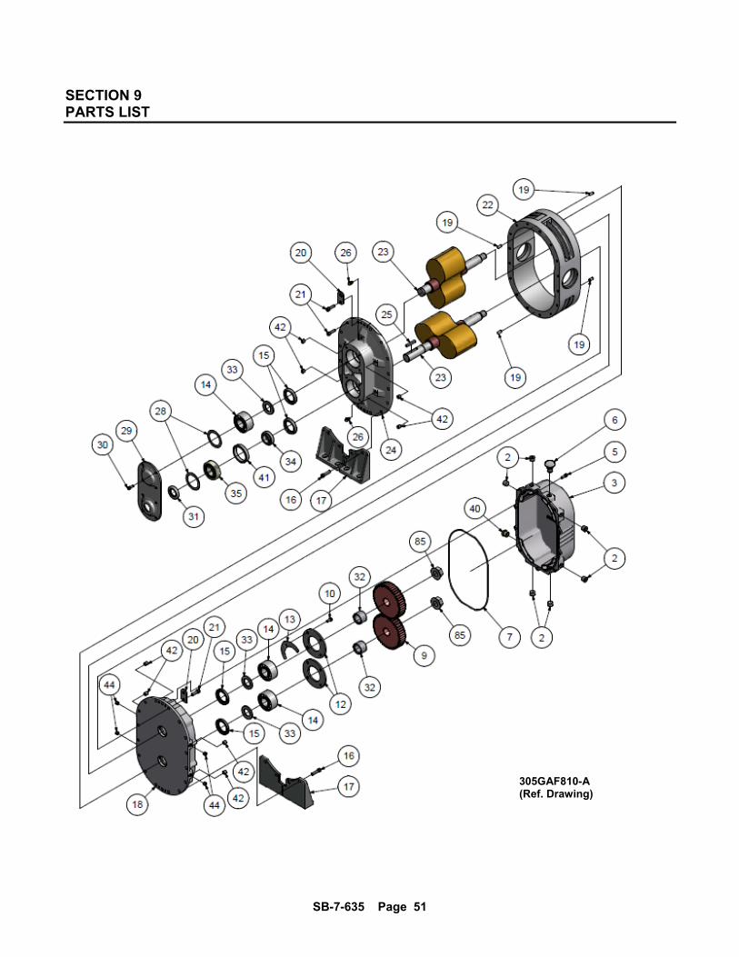
SECTION 9 PARTS LIST
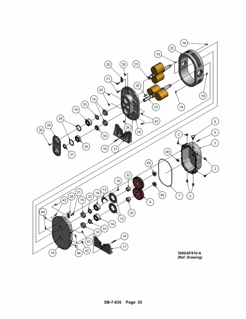
305GAF810-A (Ref. Drawing)
SB-7-635 Page 52
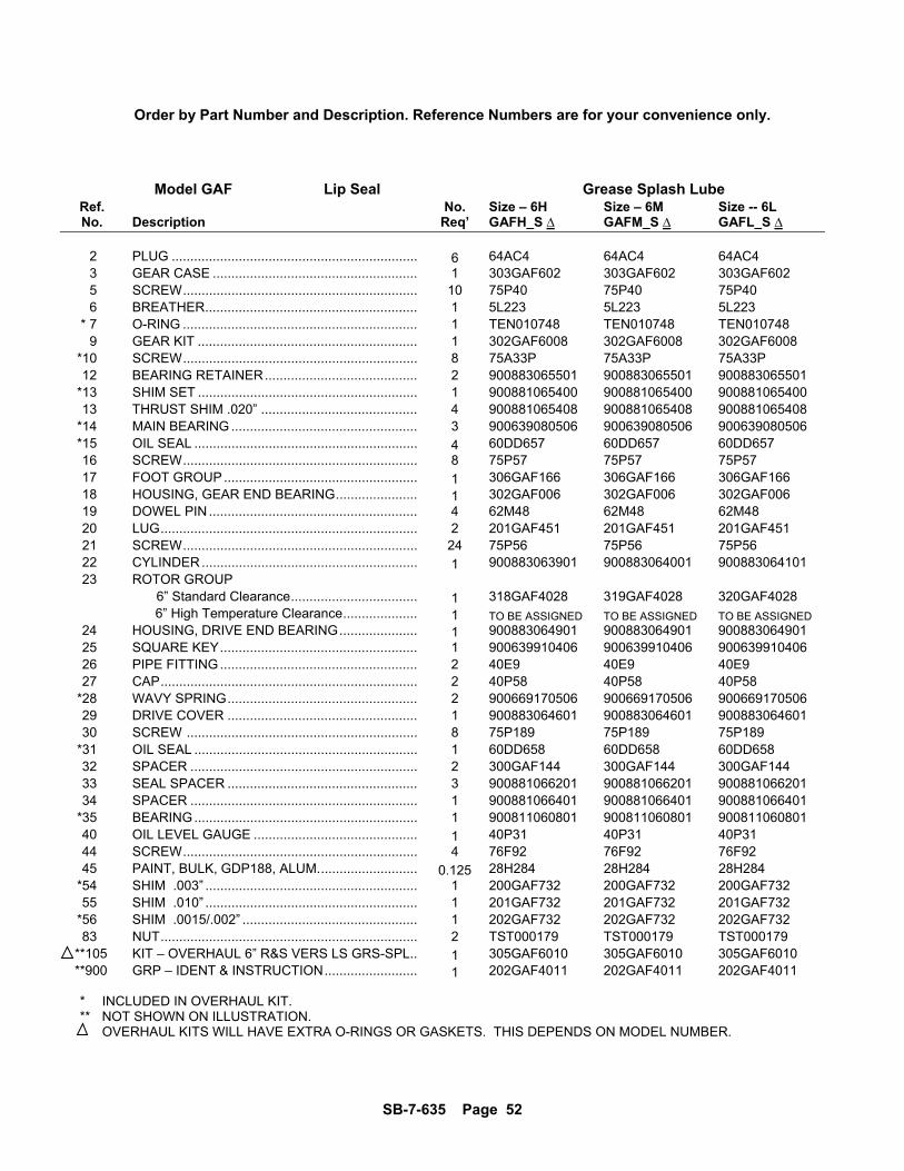
Order by Part Number and Description. Reference Numbers are for your convenience only.
Model GAF Lip Seal Grease Splash Lube Ref. No. Size – 6H Size – 6M Size -- 6L No. Description Req’ GAFH_S ∆ GAFM_S ∆ GAFL_S ∆
2 PLUG .................................................................. 6 64AC4 64AC4 64AC4 3 GEAR CASE ....................................................... 1 303GAF602 303GAF602 303GAF602 5 SCREW ............................................................... 10 75P40 75P40 75P40 6 BREATHER ......................................................... 1 5L223 5L223 5L223 * 7 O-RING ............................................................... 1 TEN010748 TEN010748 TEN010748 9 GEAR KIT ........................................................... 1 302GAF6008 302GAF6008 302GAF6008 *10 SCREW ............................................................... 8 75A33P 75A33P 75A33P 12 BEARING RETAINER ......................................... 2 900883065501 900883065501 900883065501 *13 SHIM SET ........................................................... 1 900881065400 900881065400 900881065400 13 THRUST SHIM .020” .......................................... 4 900881065408 900881065408 900881065408 *14 MAIN BEARING .................................................. 3 900639080506 900639080506 900639080506 *15 OIL SEAL ............................................................ 4 60DD657 60DD657 60DD657 16 SCREW ............................................................... 8 75P57 75P57 75P57 17 FOOT GROUP .................................................... 1 306GAF166 306GAF166 306GAF166 18 HOUSING, GEAR END BEARING ...................... 1 302GAF006 302GAF006 302GAF006 19 DOWEL PIN ........................................................ 4 62M48 62M48 62M48 20 LUG ..................................................................... 2 201GAF451 201GAF451 201GAF451 21 SCREW ............................................................... 24 75P56 75P56 75P56 22 CYLINDER .......................................................... 1 900883063901 900883064001 900883064101 23 ROTOR GROUP 6” Standard Clearance .................................. 1 318GAF4028 319GAF4028 320GAF4028 6” High Temperature Clearance .................... 1 TO BE ASSIGNED TO BE ASSIGNED TO BE ASSIGNED 24 HOUSING, DRIVE END BEARING ..................... 1 900883064901 900883064901 900883064901 25 SQUARE KEY ..................................................... 1 900639910406 900639910406 900639910406 26 PIPE FITTING ..................................................... 2 40E9 40E9 40E9 27 CAP ..................................................................... 2 40P58 40P58 40P58 *28 WAVY SPRING ................................................... 2 900669170506 900669170506 900669170506 29 DRIVE COVER ................................................... 1 900883064601 900883064601 900883064601 30 SCREW .............................................................. 8 75P189 75P189 75P189 *31 OIL SEAL ............................................................ 1 60DD658 60DD658 60DD658 32 SPACER ............................................................. 2 300GAF144 300GAF144 300GAF144 33 SEAL SPACER ................................................... 3 900881066201 900881066201 900881066201 34 SPACER ............................................................. 1 900881066401 900881066401 900881066401 *35 BEARING ............................................................ 1 900811060801 900811060801 900811060801 40 OIL LEVEL GAUGE ............................................ 1 40P31 40P31 40P31 44 SCREW ............................................................... 4 76F92 76F92 76F92 45 PAINT, BULK, GDP188, ALUM. .......................... 0.125 28H284 28H284 28H284 *54 SHIM .003” ......................................................... 1 200GAF732 200GAF732 200GAF732 55 SHIM .010” ......................................................... 1 201GAF732 201GAF732 201GAF732 *56 SHIM .0015/.002” ............................................... 1 202GAF732 202GAF732 202GAF732 83 NUT ..................................................................... 2 TST000179 TST000179 TST000179 **105 KIT – OVERHAUL 6” R&S VERS LS GRS-SPL .. 1 305GAF6010 305GAF6010 305GAF6010 **900 GRP – IDENT & INSTRUCTION ......................... 1 202GAF4011 202GAF4011 202GAF4011
* INCLUDED IN OVERHAUL KIT. ** NOT SHOWN ON ILLUSTRATION. OVERHAUL KITS WILL HAVE EXTRA O-RINGS OR GASKETS. THIS DEPENDS ON MODEL NUMBER.
SB-7-635 Page 53
306GAF810-A(Ref. Drawing)
SB-7-635 Page 54
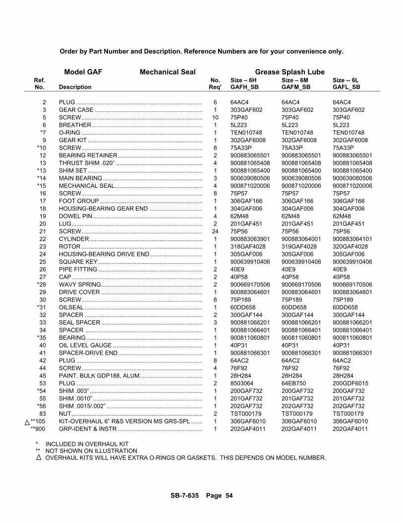
Order by Part Number and Description. Reference Numbers are for your convenience only.
Model GAF Mechanical Seal Grease Splash Lube Ref. No. Size – 6H Size – 6M Size -- 6L No. Description Req’ GAFH_SB GAFM_SB GAFL_SB
2 PLUG ............................................................................ 6 64AC4 64AC4 64AC4 3 GEAR CASE ................................................................. 1 303GAF602 303GAF602 303GAF602 5 SCREW ......................................................................... 10 75P40 75P40 75P40 6 BREATHER ................................................................... 1 5L223 5L223 5L223 *7 O-RING ......................................................................... 1 TEN010748 TEN010748 TEN010748 9 GEAR KIT ..................................................................... 1 302GAF6008 302GAF6008 302GAF6008 *10 SCREW ......................................................................... 8 75A33P 75A33P 75A33P 12 BEARING RETAINER ................................................... 2 900883065501 900883065501 900883065501 13 THRUST SHIM .020” .................................................... 4 900881065408 900881065408 900881065408 *13 SHIM SET ..................................................................... 1 900881065400 900881065400 900881065400 *14 MAIN BEARING ............................................................ 3 900639080506 900639080506 900639080506 *15 MECHANICAL SEAL..................................................... 4 900871020006 900871020006 900871020006 16 SCREW ......................................................................... 8 75P57 75P57 75P57 17 FOOT GROUP .............................................................. 1 306GAF166 306GAF166 306GAF166 18 HOUSING-BEARING GEAR END ................................ 1 304GAF006 304GAF006 304GAF006 19 DOWEL PIN .................................................................. 4 62M48 62M48 62M48 20 LUG ............................................................................... 2 201GAF451 201GAF451 201GAF451 21 SCREW ......................................................................... 24 75P56 75P56 75P56 22 CYLINDER .................................................................... 1 900883063901 900883064001 900883064101 23 ROTOR ......................................................................... 1 318GAF4028 319GAF4028 320GAF4028 24 HOUSING-BEARING DRIVE END ................................ 1 305GAF006 305GAF006 305GAF006 25 SQUARE KEY ............................................................... 1 900639910406 900639910406 900639910406 26 PIPE FITTING ............................................................... 2 40E9 40E9 40E9 27 CAP ............................................................................... 2 40P58 40P58 40P58 *28 WAVY SPRING ............................................................. 2 900669170506 900669170506 900669170506 29 DRIVE COVER ............................................................. 1 900883064601 900883064601 900883064601 30 SCREW ......................................................................... 8 75P189 75P189 75P189 *31 OILSEAL ....................................................................... 1 60DD658 60DD658 60DD658 32 SPACER ....................................................................... 2 300GAF144 300GAF144 300GAF144 33 SEAL SPACER ............................................................. 3 900881066201 900881066201 900881066201 34 SPACER ....................................................................... 1 900881066401 900881066401 900881066401 *35 BEARING ...................................................................... 1 900811060801 900811060801 900811060801 40 OIL LEVEL GAUGE ...................................................... 1 40P31 40P31 40P31 41 SPACER-DRIVE END ................................................... 1 900881066301 900881066301 900881066301 42 PLUG ............................................................................ 8 64AC2 64AC2 64AC2 44 SCREW ......................................................................... 4 76F92 76F92 76F92 45 PAINT, BULK GDP188, ALUM. ..................................... 1 28H284 28H284 28H284 53 PLUG ............................................................................ 2 8503064 64EB750 200GDF6015 *54 SHIM .003” .................................................................... 1 200GAF732 200GAF732 200GAF732 55 SHIM .0010” .................................................................. 1 201GAF732 201GAF732 201GAF732 *56 SHIM .0015/.002” .......................................................... 1 202GAF732 202GAF732 202GAF732 83 NUT ............................................................................... 2 TST000179 TST000179 TST000179
**105 KIT-OVERHAUL 6” R&S VERSION MS GRS-SPL ....... 1 306GAF6010 306GAF6010 306GAF6010 **900 GRP-IDENT & INSTR ................................................... 1 202GAF4011 202GAF4011 202GAF4011
* INCLUDED IN OVERHAUL KIT ** NOT SHOWN ON ILLUSTRATION OVERHAUL KITS WILL HAVE EXTRA O-RINGS OR GASKETS. THIS DEPENDS ON MODEL NUMBER.

SB-7-635 Page 55
307GAF810-A(Ref. Drawing)
SB-7-635 Page 56
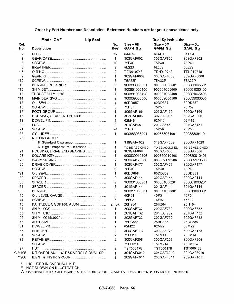
Order by Part Number and Description. Reference Numbers are for your convenience only.
Model GAF Lip Seal Dual Splash Lube Ref. No. Size – 6H Size – 6M Size -- 6L No. Description Req’ GAFH_S ∆ GAFM_S ∆ GAFL_S ∆
2 PLUG ................................................................... 12 64AC4 64AC4 64AC4 3 GEAR CASE ........................................................ 1 303GAF602 303GAF602 303GAF602 5 SCREW ............................................................... 10 75P40 75P40 75P40 6 BREATHER ......................................................... 2 5L223 5L223 5L223 * 7 O-RING ................................................................ 2 TEN010748 TEN010748 TEN010748 9 GEAR KIT ............................................................ 1 302GAF6008 302GAF6008 302GAF6008 *10 SCREW ............................................................... 8 75A33P 75A33P 75A33P 12 BEARING RETAINER ......................................... 2 900883065501 900883065501 900883065501 *13 SHIM SET ............................................................ 1 900881065400 900881065400 900881065400 13 THRUST SHIM .020” ........................................... 4 900881065408 900881065408 900881065408 *14 MAIN BEARING .................................................. 2 900639080506 900639080506 900639080506 *15 OIL SEAL ............................................................. 4 60DD657 60DD657 60DD657 16 SCREW ............................................................... 8 75P57 75P57 75P57 17 FOOT GROUP .................................................... 1 306GAF166 306GAF166 306GAF166 18 HOUSING, GEAR END BEARING ...................... 1 302GAF006 302GAF006 302GAF006 19 DOWEL PIN ........................................................ 4 62M48 62M48 62M48 20 LUG ..................................................................... 2 201GAF451 201GAF451 201GAF451 21 SCREW ............................................................... 24 75P56 75P56 75P56 22 CYLINDER .......................................................... 1 900883063901 900883064001 900883064101 23 ROTOR GROUP 6” Standard Clearance .................................. 1 318GAF4028 319GAF4028 320GAF4028 6” High Temperature Clearance .................... 1 TO BE ASSIGNED TO BE ASSIGNED TO BE ASSIGNED 24 HOUSING, DRIVE END BEARING ..................... 1 303GAF006 303GAF006 303GAF006 25 SQUARE KEY ..................................................... 1 900639910406 900639910406 900639910406 *28 WAVY SPRING ................................................... 2 900669170506 900669170506 900669170506 29 DRIVE COVER .................................................... 1 302GAF477 302GAF477 302GAF477 30 SCREW ............................................................... 10 75P40 75P40 75P40 *31 OIL SEAL ............................................................. 1 60DD658 60DD658 60DD658 32 SPACER .............................................................. 2 300GAF144 300GAF144 300GAF144 33 SPACER .............................................................. 2 900881066201 900881066201 900881066201 34 SPACER .............................................................. 2 301GAF144 301GAF144 301GAF144 *35 BEARING ............................................................ 2 900811060801 900811060801 900811060801 40 OIL LEVEL GAUGE ............................................. 2 40P31 40P31 40P31 44 SCREW ............................................................... 8 76F92 76F92 76F92 45 PAINT,BULK, GDP188, ALUM. ........................... 0.125 28H284 28H284 28H194 *54 SHIM .003” ......................................................... 1 200GAF732 200GAF732 200GAF732 55 SHIM .010” ......................................................... 1 201GAF732 201GAF732 201GAF732 *56 SHIM .0015/.002” ............................................... 1 202GAF732 202GAF732 202GAF732 76 ADHESIVE .......................................................... 1 25BC885 25BC885 25BC885 81 DOWEL PIN ........................................................ 2 62M22 62M22 62M22 83 SLINGER ............................................................. 2 300GAF173 300GAF173 300GAF173 84 SCREW ............................................................... 2 75LM14 75LM14 75LM14 85 RETAINER .......................................................... 2 300GAF205 300GAF205 300GAF205 86 SCREW ............................................................... 8 75LM214 75LM214 75LM214 87 NUT ..................................................................... 2 TST000179 TST000179 TST000179 **105 KIT OVERHAUL – 6” R&S VERS LS DUAL-SPL 1 304GAF6010 304GAF6010 304GAF6010 **900 IDENT & INSTR GROUP ..................................... 1 202GAF4011 202GAF4011 202GAF4011
* INCLUDED IN OVERHAUL KIT. ** NOT SHOWN ON ILLUSTRATION OVERHAUL KITS WILL HAVE EXTRA O-RINGS OR GASKETS. THIS DEPENDS ON MODEL NUMBER.
SB-7-635 Page 57
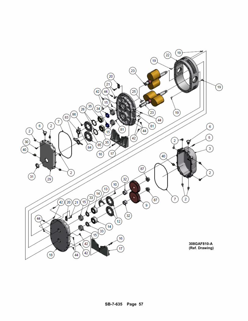
308GAF810-A(Ref. Drawing)
SB-7-635 Page 58
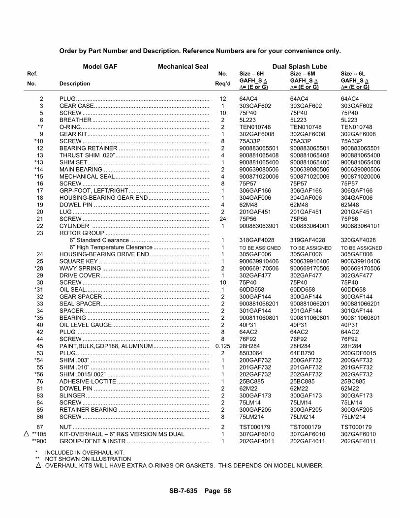
Order by Part Number and Description. Reference Numbers are for your convenience only.
Model GAF Mechanical Seal Dual Splash Lube Ref. No. Size – 6H Size – 6M Size -- 6L
No. Description Req’d GAFH_S ∆ ∆= (E or G)
GAFH_S ∆ ∆= (E or G)
GAFH_S ∆ ∆= (E or G)
2 PLUG ................................................................................. 12 64AC4 64AC4 64AC4 3 GEAR CASE ...................................................................... 1 303GAF602 303GAF602 303GAF602 5 SCREW ............................................................................. 10 75P40 75P40 75P40 6 BREATHER ....................................................................... 2 5L223 5L223 5L223 *7 O-RING .............................................................................. 2 TEN010748 TEN010748 TEN010748 9 GEAR KIT .......................................................................... 1 302GAF6008 302GAF6008 302GAF6008 *10 SCREW ............................................................................. 8 75A33P 75A33P 75A33P 12 BEARING RETAINER ....................................................... 2 900883065501 900883065501 900883065501 13 THRUST SHIM .020” ......................................................... 4 900881065408 900881065408 900881065400 *13 SHIM SET .......................................................................... 1 900881065400 900881065400 900881065408 *14 MAIN BEARING ................................................................ 2 900639080506 900639080506 900639080506 *15 MECHANICAL SEAL ......................................................... 4 900871020006 900871020006 900871020006 16 SCREW ............................................................................. 8 75P57 75P57 75P57 17 GRP-FOOT, LEFT/RIGHT ................................................. 1 306GAF166 306GAF166 306GAF166 18 HOUSING-BEARING GEAR END ..................................... 1 304GAF006 304GAF006 304GAF006 19 DOWEL PIN ...................................................................... 4 62M48 62M48 62M48 20 LUG ................................................................................... 2 201GAF451 201GAF451 201GAF451 21 SCREW ............................................................................. 24 75P56 75P56 75P56 22 CYLINDER ....................................................................... 1 900883063901 900883064001 900883064101 23 ROTOR GROUP ............................................................... 6” Standard Clearance ................................................ 1 318GAF4028 319GAF4028 320GAF4028 6” High Temperature Clearance .................................. 1 TO BE ASSIGNED TO BE ASSIGNED TO BE ASSIGNED 24 HOUSING-BEARING DRIVE END .................................... 1 305GAF006 305GAF006 305GAF006 25 SQUARE KEY ................................................................... 1 900639910406 900639910406 900639910406 *28 WAVY SPRING ................................................................. 2 900669170506 900669170506 900669170506 29 DRIVE COVER .................................................................. 1 302GAF477 302GAF477 302GAF477 30 SCREW ............................................................................. 10 75P40 75P40 75P40 *31 OIL SEAL ........................................................................... 1 60DD658 60DD658 60DD658 32 GEAR SPACER ................................................................. 2 300GAF144 300GAF144 300GAF144 33 SEAL SPACER .................................................................. 2 900881066201 900881066201 900881066201 34 SPACER ............................................................................ 2 301GAF144 301GAF144 301GAF144 *35 BEARING .......................................................................... 2 900811060801 900811060801 900811060801 40 OIL LEVEL GAUGE ........................................................... 2 40P31 40P31 40P31 42 PLUG ................................................................................ 8 64AC2 64AC2 64AC2 44 SCREW ............................................................................. 8 76F92 76F92 76F92 45 PAINT,BULK,GDP188, ALUMINUM .................................. 0.125 28H284 28H284 28H284 53 PLUG ................................................................................. 2 8503064 64EB750 200GDF6015 *54 SHIM .003” ........................................................................ 1 200GAF732 200GAF732 200GAF732 55 SHIM .010” ........................................................................ 1 201GAF732 201GAF732 201GAF732 *56 SHIM .0015/.002” .............................................................. 1 202GAF732 202GAF732 202GAF732 76 ADHESIVE-LOCTITE ........................................................ 1 25BC885 25BC885 25BC885 81 DOWEL PIN ...................................................................... 2 62M22 62M22 62M22 83 SLINGER ........................................................................... 2 300GAF173 300GAF173 300GAF173 84 SCREW ............................................................................. 2 75LM14 75LM14 75LM14 85 RETAINER BEARING ....................................................... 2 300GAF205 300GAF205 300GAF205 86 SCREW ............................................................................. 8 75LM214 75LM214 75LM214
87 NUT ................................................................................... 2 TST000179 TST000179 TST000179 **105 KIT-OVERHAUL – 6” R&S VERSION MS DUAL 1 307GAF6010 307GAF6010 307GAF6010 **900 GROUP-IDENT & INSTR .................................................. 1 202GAF4011 202GAF4011 202GAF4011
* INCLUDED IN OVERHAUL KIT. ** NOT SHOWN ON ILLUSTRATION OVERHAUL KITS WILL HAVE EXTRA O-RINGS OR GASKETS. THIS DEPENDS ON MODEL NUMBER.
SB-7-635 Page 59

NOTES:

NOTES:

NOTES:
