“p” series blowers - carotek quick order · “p” series blowers 6” -- 8” gear diameter....
TRANSCRIPT

PARTS LISTOPERATING ANDSERVICE MANUAL
SB--7--622Version 03November, 2005
ModelsGAF_ _P_GAG_ _P_GAH_ _P_
LEGEND
“P” SERIESBLOWERS
6” -- 8” GEAR DIAMETER
SB--7--622 Page i
MAINTAIN BLOWER RELIABILITY AND PERFORMANCEWITH GENUINE GARDNER DENVERPARTS AND SUPPORT SERVICES
Factory genuine parts, manufactured to design toler-ances, are developed for optimum dependability ------specifically for your blower. Designandmaterial innova-tions are born from years of experience with hundredsof different blower applications. When you specifyfactory genuineparts youare assuredof receivingpartsthat incorporate themost current designadvancements. . . manufactured in our state--of--the--art blower factoryunder exacting quality standards.
Your AUTHORIZED DISTRIBUTOR offers all thebackup you require. A worldwide network of authorizeddistributors provides the finest product support in theblower industry.
Your AUTHORIZED DISTRIBUTOR can support your
blower investment with these services:
1. Trained parts technical representatives to assistyou in selecting the correct replacement parts.
2. Complete inventory of new machines and new,genuine factory parts.
3. A full line of factory testedAEONtPDblower lubri-cants specifically formulated for optimum perfor-mance in all blowers.
4. Authorized Distributor service technicians arefactory-trained and skilled in blower maintenanceand repair. They are ready to respond and assistyou by providing fast, expert maintenance andrepair services.
INSTRUCTIONS FOR DETERMINING BLOWER CONFIGURATION
1. Face the blower drive shaft.
2. In aVERTICAL configuration, air flow is horizontal.
3. In a HORIZONTAL configuration, air flow is vertical.
4. In a vertical configuration, a BOTTOM HANDexists when the drive shaft is below the horizontalcenter line of the blower. A TOP HAND exists
when the drive shaft is above the horizontal centerline of the blower.
5. In a horizontal configuration, a RIGHT HANDexists when the drive shaft is to the right of thevertical center line of the blower. A LEFT HANDexists when the drive shaft is to the left of thevertical center line of the blower.
INSTRUCTIONS FOR ORDERING REPAIR PARTS
For pricing and ordering information, contact your nearest AUTHORIZED FACTORY DISTRIBUTOR.
When ordering parts, specify Blower MODEL and SERIAL NUMBER (see nameplate on unit).
Rely upon the knowledge and experience of your AUTHORIZED DISTRIBUTOR and let them assist you in makingthe proper parts selection for your blower.
For the location of your local authorizedGardnerDenver blowerdistributor refer to theyellowpagesofyourphone directory, check the Web site at www.gardnerdenver.com or contact:
Gardner Denver1800 Gardner ExpresswayQuincy, IL 62305Phone: (217) 222--5400Fax: (217) 221--8780

SB--7--622 Page ii
FOREWORD
SutorbiltR blowers are the result of advanced engineering and skilled manufacturing. To be assured of receivingmaximum service from this machine the owner must exercise care in its operation and maintenance. This book iswritten to give the operator and maintenance department essential information for day-to-day operation, mainte-nance and adjustment. Careful adherence to these instructions will result in economical operation and minimumdowntime.
Danger is used to indicate thepresence of a hazardwhichwill cause severepersonalinjury, death, or substantial property damage if the warning is ignored.
Warning isused to indicate thepresenceof ahazardwhich cancausesevereperson-al injury, death, or substantial property damage if the warning is ignored.
Caution is used to indicate the presence of a hazard which will or can cause minorpersonal injury or property damage if the warning is ignored.
Notice is used tonotify peopleof installation, operationormaintenance informationwhich is important but not hazard--related.

SB--7--622 Page iii
SAFETY PRECAUTIONS
Safety is everybody’s business and is based on your use of good common sense. All situations or circumstancescannot always be predicted and covered by established rules. Therefore, use your past experience, watch out forsafety hazards and be cautious. Some general safety precautions are given below:
Failure to observe these notices could result in injury to or death of personnel.
D Keep fingers and clothing away from blower inlet and discharge ports,revolving belts, sheaves, drive coupling, etc.
D Do not use the air discharge from this unit for breathing -- not suitable forhuman consumption.
D Do not loosen or remove the oil filler plug, drain plugs, covers, or break anyconnections, etc., in the blower air or oil system until the unit is shut downand the air pressure has been relieved.
D Electrical shock can and may be fatal.
D Blower unit must be grounded in accordance with the National ElectricalCode. Aground jumper equal to the size of the equipment ground conductormust be used to connect the blower motor base to the unit base.
D Open main disconnect switch, tag and lockout before working on the control.
D Disconnect the blower unit from its power source, tag and lockout beforeworking on the unit -- the machine may be automatically controlled and maystart at any time.
Failure to observe these notices could result in damage to equipment.
D Stop the unit if any repairs or adjustments on or around the blower arerequired.
D Disconnect the blower unit from its power source, tag and lockout beforeworking on the unit -- themachinemaybe automatically controlled andmaystart at any time.
D Do not exceed the rated maximum speed shown on the nameplate.
D Do not operate unit if safety devices are not operating properly. Checkperiodically. Never bypass safety devices.

SB--7--622 Page iv
TABLE OF CONTENTS
Page
Maintain Blower Reliability and Performance with Genuine Gardner Denver Parts and Support Services i. . . . . .
Instructions for Ordering Repair Parts i. . . . . . . . . . . . . . . . . . . . . . . . . . . . . . . . . . . . . . . . . . . . . . . . . . . . . . . . . . . . . . . .
Instructions for Determining Blower Configuration i. . . . . . . . . . . . . . . . . . . . . . . . . . . . . . . . . . . . . . . . . . . . . . . . . . . . . .
Foreword ii. . . . . . . . . . . . . . . . . . . . . . . . . . . . . . . . . . . . . . . . . . . . . . . . . . . . . . . . . . . . . . . . . . . . . . . . . . . . . . . . . . . . . . . . .
Safety Precautions iii. . . . . . . . . . . . . . . . . . . . . . . . . . . . . . . . . . . . . . . . . . . . . . . . . . . . . . . . . . . . . . . . . . . . . . . . . . . . . . .
Index v. . . . . . . . . . . . . . . . . . . . . . . . . . . . . . . . . . . . . . . . . . . . . . . . . . . . . . . . . . . . . . . . . . . . . . . . . . . . . . . . . . . . . . . . . . . .
List of Illustrations v. . . . . . . . . . . . . . . . . . . . . . . . . . . . . . . . . . . . . . . . . . . . . . . . . . . . . . . . . . . . . . . . . . . . . . . . . . . . . . . . .
Sutorbilt Legend Series Sutorbilt Blowers Matrix/Menu vi. . . . . . . . . . . . . . . . . . . . . . . . . . . . . . . . . . . . . . . . . . . . . . . .
Introduction, Your Key To Trouble Free Service 1. . . . . . . . . . . . . . . . . . . . . . . . . . . . . . . . . . . . . . . . . . . . . . . . . . . . . . . .
Section 1, Equipment Check 2. . . . . . . . . . . . . . . . . . . . . . . . . . . . . . . . . . . . . . . . . . . . . . . . . . . . . . . . . . . . . . . . . . . . . . . .
Section 2, Installation 3. . . . . . . . . . . . . . . . . . . . . . . . . . . . . . . . . . . . . . . . . . . . . . . . . . . . . . . . . . . . . . . . . . . . . . . . . . . . . .
Section 3, Lubrication 6. . . . . . . . . . . . . . . . . . . . . . . . . . . . . . . . . . . . . . . . . . . . . . . . . . . . . . . . . . . . . . . . . . . . . . . . . . . . . .
Section 4, Operation 8. . . . . . . . . . . . . . . . . . . . . . . . . . . . . . . . . . . . . . . . . . . . . . . . . . . . . . . . . . . . . . . . . . . . . . . . . . . . . . .
Section 5, Special Tools Required 11. . . . . . . . . . . . . . . . . . . . . . . . . . . . . . . . . . . . . . . . . . . . . . . . . . . . . . . . . . . . . . . . . .
Section 6, Disassembly Instructions 15. . . . . . . . . . . . . . . . . . . . . . . . . . . . . . . . . . . . . . . . . . . . . . . . . . . . . . . . . . . . . . . . .
Section 7, Assembly Instructions 18. . . . . . . . . . . . . . . . . . . . . . . . . . . . . . . . . . . . . . . . . . . . . . . . . . . . . . . . . . . . . . . . . . .
Section 8, Parts List 25. . . . . . . . . . . . . . . . . . . . . . . . . . . . . . . . . . . . . . . . . . . . . . . . . . . . . . . . . . . . . . . . . . . . . . . . . . . . . .
Warranty Last Page. . . . . . . . . . . . . . . . . . . . . . . . . . . . . . . . . . . . . . . . . . . . . . . . . . . . . . . . . . . . . . . . . . . . . . . . . . . . . . . . .

SB--7--622 Page v
INDEX
Air Filters and Filter--Silencers 7. . . . . . . . . . . . . . . . .ASSEMBLY INSTRUCTIONS, SECTION 7 18. . . . .
Blower Configuration, Determining i. . . . . . . . . . . . . . .Blower Startup Checklist 9. . . . . . . . . . . . . . . . . . . . . .
Checklist, Blower Startup 9. . . . . . . . . . . . . . . . . . . . . .
DISASSEMBLY INSTRUCTIONS, SECTION 6 15. .Drive End Lubrication 7. . . . . . . . . . . . . . . . . . . . . . . . .Drive Installation 4. . . . . . . . . . . . . . . . . . . . . . . . . . . . .
EQUIPMENT CHECK, SECTION 1 2. . . . . . . . . . . .
Filter--Silencers and Air Filters 7. . . . . . . . . . . . . . . . .Foreword ii. . . . . . . . . . . . . . . . . . . . . . . . . . . . . . . . . . . .Foundation 3. . . . . . . . . . . . . . . . . . . . . . . . . . . . . . . . . .
Gear End Lubrication 6. . . . . . . . . . . . . . . . . . . . . . . . .
Impeller End Clearance, Setting, 22. . . . . . . . . . . . . .INSTALLATION, SECTION 2 3. . . . . . . . . . . . . . . . . .Installation, Location 3. . . . . . . . . . . . . . . . . . . . . . . . . .Installation, Drive 4. . . . . . . . . . . . . . . . . . . . . . . . . . . . .Installing Timing Gears 22. . . . . . . . . . . . . . . . . . . . . . .
Limitations, Operation 8. . . . . . . . . . . . . . . . . . . . . . . . .Location, Installation 3. . . . . . . . . . . . . . . . . . . . . . . . . .Lubricant, Recommended 6. . . . . . . . . . . . . . . . . . . . .LUBRICATION, SECTION 3 6. . . . . . . . . . . . . . . . . . .Lubrication
Drive End 7. . . . . . . . . . . . . . . . . . . . . . . . . . . . . . . .Filling Procedure 6. . . . . . . . . . . . . . . . . . . . . . . . . .
Gear End 6. . . . . . . . . . . . . . . . . . . . . . . . . . . . . . . .Lubrication Service 6. . . . . . . . . . . . . . . . . . . . . . . . . . .
Matrix/Menu vi. . . . . . . . . . . . . . . . . . . . . . . . . . . . . . . . .Mechanical Seals, Assembly 19. . . . . . . . . . . . . . . . . .Mounting Configurations 3. . . . . . . . . . . . . . . . . . . . . . .Mounting Feet, Repositioning 3. . . . . . . . . . . . . . . . . .
OPERATION, SECTION 4 8. . . . . . . . . . . . . . . . . . . . .Outline Drawing and Parts List
Model GAF 25, 26. . . . . . . . . . . . . . . . . . . . . . . . . .Model GAG 27, 28. . . . . . . . . . . . . . . . . . . . . . . . . .Model GAH 29, 30. . . . . . . . . . . . . . . . . . . . . . . . . .
PARTS LIST, SECTION 5 25. . . . . . . . . . . . . . . . . . . .Piping 4. . . . . . . . . . . . . . . . . . . . . . . . . . . . . . . . . . . . . . .Precautions, Safety 10. . . . . . . . . . . . . . . . . . . . . . . . . .Protective Materials, Removing 2. . . . . . . . . . . . . . . .
Recommended Lubricant 6. . . . . . . . . . . . . . . . . . . . . .Removing Protective Materials 2. . . . . . . . . . . . . . . . .Repair Parts, Ordering Instructions i. . . . . . . . . . . . . .
Safety Precautions iii, 10. . . . . . . . . . . . . . . . . . . . . . . .Setting Impeller End Clearance 22. . . . . . . . . . . . . . . .SPECIAL TOOLS REQUIRED, SECTION 5 11. . . .Startup Checklist, Blower 9. . . . . . . . . . . . . . . . . . . . . .Storage 2. . . . . . . . . . . . . . . . . . . . . . . . . . . . . . . . . . . . .
Timing Gears, Installing 22. . . . . . . . . . . . . . . . . . . . . .Trouble Shooting 10. . . . . . . . . . . . . . . . . . . . . . . . . . . .
YOUR KEY TO TROUBLE FREE SERVICE,INTRODUCTION 1. . . . . . . . . . . . . . . . . . . . . . . . .
LIST OF ILLUSTRATIONS
Figure 1 Blower Mounting Configuration 3. . . . . . . . . . . . . . . . . . . . . . . . . . . . . . . . . . . . . . . . . . . . . . . . . . . . . . .
Figure 2 Belt Drive Overhung Load Calculations 5. . . . . . . . . . . . . . . . . . . . . . . . . . . . . . . . . . . . . . . . . . . . . . . .
Figure 3 Lubrication 6. . . . . . . . . . . . . . . . . . . . . . . . . . . . . . . . . . . . . . . . . . . . . . . . . . . . . . . . . . . . . . . . . . . . . . . .
Figure 4 Approximate Oil Capacities 6. . . . . . . . . . . . . . . . . . . . . . . . . . . . . . . . . . . . . . . . . . . . . . . . . . . . . . . . . .
Figure 5 Lubrication Recommendation 7. . . . . . . . . . . . . . . . . . . . . . . . . . . . . . . . . . . . . . . . . . . . . . . . . . . . . . . .
Figure 6 Temperature Chart 7. . . . . . . . . . . . . . . . . . . . . . . . . . . . . . . . . . . . . . . . . . . . . . . . . . . . . . . . . . . . . . . . .
Figure 7 Maximum Operating Limitations 8. . . . . . . . . . . . . . . . . . . . . . . . . . . . . . . . . . . . . . . . . . . . . . . . . . . . . .
Figure 8 Puller Plate -- SK2154 11. . . . . . . . . . . . . . . . . . . . . . . . . . . . . . . . . . . . . . . . . . . . . . . . . . . . . . . . . . . .
Figure 9 Puller Plate -- SK2150 12. . . . . . . . . . . . . . . . . . . . . . . . . . . . . . . . . . . . . . . . . . . . . . . . . . . . . . . . . . . .
Figure 10 Mechanical Seal Installation Tool -- SK2152 13. . . . . . . . . . . . . . . . . . . . . . . . . . . . . . . . . . . . . . . . . . .
Figure 11 Bearing Press Tool -- Mechanical Seal Units 14. . . . . . . . . . . . . . . . . . . . . . . . . . . . . . . . . . . . . . . . .
Figure 24 Torque (Ft--Lbs) 24. . . . . . . . . . . . . . . . . . . . . . . . . . . . . . . . . . . . . . . . . . . . . . . . . . . . . . . . . . . . . . . . . . .

SB--7--622 Page vi
COLUMN 1 -- BASIC DESIGNATOR
COLUMN 2 -- PRODUCT FAMILY
COLUMN 3 -- GEAR DIAMETERF. 6”G. 7”H. 8”
COLUMN 4 -- CASE LENGTHL -- Low PressureM -- Medium PressureH -- High Pressure
COLUMN 5 -- CONFIGURATIONA. Vertical--Top Hand--Central TimedB. Vertical--Bottom Hand--Central TimedC. Horizontal--Left Hand--Central TimedD. Horizontal--Right Hand--Central Timed
COLUMN 6 -- DESIGN VERSION
COLUMN 7 -- ADDITIONAL DESCRIPTIONA. Lip SealB. Mechanical Seal
SUTORBILT LEGEND SERIES SUTORBILT BLOWERSMATRIX/MENU
NOTICE TO CUSTOMER -- To find the construction options foryour blower unit, FILL IN THE BALANCE OF LETTERS ORNUMBERS FROM YOUR UNIT NAMEPLATE
COLUMN NUMBER:
FOLLOWTHELINEDOWNANDOVERFROMEACHSPACETHUS FILLED IN TO FIND THE APPROPRIATECONSTRUCTION OPTION WITH WHICH YOUR MACHINEIS EQUIPPED.
G A P__ __ __ __ __ __ __1 2 3 4 5 6 7

SB--7--622 Page 1
INTRODUCTIONYOUR KEY TO TROUBLE FREE SERVICE
Thank you for investing in Sutorbilt quality. The Sutor-bilt reputation for rugged dependability has beenearned by over 50 years of service in demanding,industrial operations where downtime cannot betoleratedandefficient blower performance is expected.
Your Sutorbilt blower is a precision engineered blowerthat has been carefully manufactured and thoroughlytested at the state-of-the-art Gardner Denver BlowerFactory in Sedalia, Missouri.
As with other precision machinery, there are severalrelatively simple installation, operation and mainte-
nance procedures that you must observe to assureoptimum blower performance. There is no guessworkin the manufacture of your highly advanced Sutorbiltblower and there must be none in preparing the blowerto get the job done in the field.
The purpose of this manual is to help you properlyinstall, operate andmaintain your Sutorbilt blower. It isessential that you review all sections of this manual inpreparation for installing your blower. Follow theinstructions carefully and you will be rewarded withtrouble--free Sutorbilt service . . . year in and year out.

SB--7--622 Page 2
SECTION 1EQUIPMENT CHECK
Before uncrating, check the packing slip carefully to besure all the parts have been received. All accessoriesare listed as separate items on the packing slip, andsmall important accessories such as relief valves canbe overlooked or lost. After every item on the packingslip has been checked off, uncrate carefully. Registera claim with the carrier for lost or damaged equipment.
Customers are cautioned to provideadequate protection, warning andsafety equipment necessary to protectpersonnel against hazards involved ininstallation and operation of thisequipment in the system or facility.
STORAGE
Your Sutorbilt Blower was packaged at the factory withadequate protection to permit normal storage for up tosix (6) months.
If the unit is to be stored under adverse conditions orfor extended periods of time, the following additionalmeasures should be taken to prevent damage.
1. Store the blower in a clean, dry, heated (ifpossible) area.
2. Make certain inlet and discharge air ports aretightly covered to prevent foreign material fromentering the air box.
3. All exposed, non--painted surfaces should beprotected against rust and corrosion.
4. Provide adequate protection to avoid accidentalmechanical damage.
5. In high humidity or corrosive environments, addi-tional measures may be required to prevent rust-ing of the blower internal surfaces.
6. To prevent rusting of gears, bearings, etc., the oilreservoirs may be filled with normal operating oil.
Before running the blower, drain theoil and replace to the proper operat-ing level with clean, fresh lubricant.
7. Rotate the blower shaft (10 to 25 turns) monthlyduring storage. Inspect the blower shaft (near theshaft seal area) monthly and spraywith rust inhibi-tor if needed.
8. For long term storage (over six (6) months),contact Sutorbilt Customer Service for recom-mendations.
REMOVING PROTECTIVE MATERIALS
The shaft extension is protected with rust inhibitorwhich can be removed with any standard solvent.
Follow the safety directions of thesolvent manufacturer.
Blower inlet and outlet are temporarily capped to keepout dirt and other contaminants during shipment.These covers must be removed before start--up.
The internal surfaces of all Sutorbilt units are mistsprayedwith a rust preventative to protect themachineduring shipment. Remove this film upon initial startup,using any commercial safety solvent. Care should beexercised to lock out the blower to prevent start--up
Rotating components will causesevere injury in case of personalcontact. Keep handsaway fromblow-er inlet and discharge ports.

SB--7--622 Page 3
SECTION 2INSTALLATION
LOCATION
If possible, install the blower in awell lit, clean, dryplacewith plenty of room for inspection and maintenance.
FOUNDATIONS
For permanent installations we recommend concretefoundations be provided, and the equipment should begrouted to the concrete. It is necessary that a suitablebase be used, such as a steel combination base underblower andmotor, or a separate sole plate under each.Before grouting, equipment must be leveled, free of allstrains, and anchored so no movement will occurduring setting of grout. After grout has completelyhardened, a recheck is necessary to compensate forshrinkage, etc. If required, add shims under blower feetafter final tightening of foundation anchor bolts toremove strain from the blower housing.
Where jack screws or wedges are used duringgrouting, they must be backed off or removed beforefinal tightening of anchor bolts.
Where a concrete foundation is not feasible, caremustbe taken to insure that equipment is firmly anchored toadequate structural members.
MOUNTING CONFIGURATIONS
The blower flex--mount design enables horizontal andvertical mounting configurations with top or bottomhand, right or left hand shaft positioning. The units arecenter timed allowing rotation in either direction (referto FIGURE 1). If converting a blower from vertical tohorizontal, or horizontal to vertical mounting configura-tion, additional mounting feet will be required.
REPOSITIONING THE MOUNTING FEET:
1. Position the mounting feet to the desired locationand snug the capscrew.
2. Place the blower on its feet on a flat surface.
3. Loosen mounting feet capscrews and level unitup. The bench or blower base flatness should bewithin .002 of an inch.
If the unit is not flat within .002 of aninch, it will be necessary to shim theblower feet at installation.
FIGURE 1 -- BLOWER MOUNTING CONFIGURATIONS
SB--7--622 Page 4
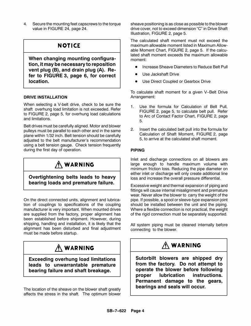
4. Secure themounting feet capscrews to the torquevalue in FIGURE 24, page 24.
When changing mounting configura-tion, itmaybenecessary to repositionvent plug (B), and drain plug (A). Re-fer to FIGURE 3, page 6, for correctlocation.
DRIVE INSTALLATION
When selecting a V-belt drive, check to be sure theshaft overhung load limitation is not exceeded. Referto FIGURE 2, page 5, for overhung load calculationsand limitations.
Belt drivesmust be carefully aligned. Motor and blowerpulleys must be parallel to each other and in the sameplane within 1/32 inch. Belt tension should be carefullyadjusted to the belt manufacturer’s recommendationusing a belt tension gauge. Check tension frequentlyduring the first day of operation.
Overtightening belts leads to heavybearing loads and premature failure.
On the direct connected units, alignment and lubrica-tion of couplings to specifications of the couplingmanufacturer is very important. When mounted drivesare supplied from the factory, proper alignment hasbeen established before shipment. However, duringshipping, handling and installation, it is likely that thealignment has been disturbed and final adjustmentmust be made before startup.
Exceeding overhung load limitationsleads to unwarrantable prematurebearing failure and shaft breakage.
The location of the sheave on the blower shaft greatlyaffects the stress in the shaft. The optimum blower
sheave positioning is as close as possible to theblowerdrive cover, not to exceed dimension “C” in Drive ShaftIllustration, FIGURE 2, page 5.
The calculated shaft moment must not exceed themaximum allowable moment listed in Maximum Allow-able Moment Chart, FIGURE 2, page 5. If the calcu-lated shaft moment exceeds the maximum allowablemoment:
D Increase Sheave Diameters to Reduce Belt Pull
D Use Jackshaft Drive
D Use Direct Coupled or Gearbox Drive
To calculate shaft moment for a given V--Belt DriveArrangement:
1. Use the formula for Calculation of Belt Pull,FIGURE 2, page 5, to calculate belt pull. Referto Arc of Contact Factor Chart, FIGURE 2, page5.
2. Insert the calculated belt pull into the formula forCalculation of Shaft Moment, FIGURE 2, page5, to arrive at the calculated shaft moment.
PIPING
Inlet and discharge connections on all blowers arelarge enough to handle maximum volume withminimum friction loss. Reducing the pipe diameter oneither inlet or discharge will only create additional lineloss and increase the overall pressure differential.
Excessive weight and thermal expansion of piping andfittings will cause internal misalignment and prematurewear. Never allow the blower to carry the weight of thepipe. If possible, a spool or sleeve-type expansion jointshould be installed between the unit and the piping.Where a flexible connection is not practical, the weightof the rigid connection must be separately supported.
All system piping must be cleaned internally beforeconnecting to the blower.
Sutorbilt blowers are shipped dryfrom the factory. Do not attempt tooperate the blower before followingproper lubrication instructions.Permanent damage to the gears,bearings and seals will occur.

SB--7--622 Page 5
FIGURE 2 -- BELT DRIVE OVERHUNG LOAD CALCULATIONS
Dimensions MaximumGear (Inches) AllowableDiameter Moment(Inches) A B C (LB--IN)
(Max)
6 4.08 1.14 .38 1788
7 4.50 1.31 .38 3000
8 5.57 1.77 .38 4144
Z Ac Z Ac Z Ac Z Ac Z Ac Z Ac
0.000 1.000 0.250 0.966 0.500 0.926 0.750 0.879 1.000 0.823 1.250 0.7510.025 0.997 0.275 0.962 0.525 0.922 0.775 0.874 1.025 0.816 1.275 0.7420.050 0.994 0.300 0.958 0.550 0.917 0.800 0.869 1.050 0.810 1.300 0.7340.075 0.990 0.325 0.954 0.575 0.913 0.825 0.864 1.075 0.803 1.325 0.7250.100 0.987 0.350 0.951 0.600 0.908 0.850 0.858 1.100 0.796 1.350 0.7160.125 0.983 0.375 0.947 0.625 0.904 0.875 0.852 1.125 0.789 1.375 0.7060.150 0.980 0.400 0.943 0.650 0.899 0.900 0.847 1.150 0.782 1.400 0.6970.175 0.977 0.425 0.939 0.675 0.894 0.925 0.841 1.175 0.774 1.425 0.6870.200 0.973 0.450 0.935 0.700 0.889 0.950 0.835 1.200 0.7670.225 0.969 0.475 0.930 0.725 0.884 0.975 0.829 1.225 0.759
2.5 -- Ac 125954 x Hp x S.F.Ac D x RPM
Key: Ac = Arc of Contact Factor (Refer to Arc of Contact Factors Chart above)Hp = Blower Horsepower for Operating ConditionsS.F. = Actual Drive Service FactorD = Blower Sheave Pitch Diameter in InchesRPM = Blower Sheave SpeedZ = Large Sheave Pitch Diameter (in) -- Small Sheave Pitch Diameter (in)
Sheave Center Distance (in)
[ ] [ ]Belt Pull =
Shaft Moment (LB--IN) = Belt Pull x B + C +[ ( )]Sheave Width2
CALCULATION OF BELT PULL
CALCULATION OF SHAFT MOMENT
DRIVE SHAFT ILLUSTRATIONMAXIMUM ALLOWABLE MOMENT
ARC OF CONTACT FACTORS
[ ]

SB--7--622 Page 6
SECTION 3LUBRICATION
FIGURE 3 -- LUBRICATION
A. OIL DRAIN PLUGB. BREATHER / OIL FILLC. GREASE FITTINGE. GREASE VENTSH. OIL LEVEL GAUGE
At the gear end the timing gear teeth are lubricated bybeing partially submerged in oil. The gear teeth serveas oil slingers for gear end bearings. At the drive endthe bearings are grease lubricated.
FILLING PROCEDURE
Refer to FIGURE 3. Remove the breather (B) from thegear cover. Add oil to the gear case until it reaches thecenter line of the oil level gauge (H). Secure breather(B) in its correct location.
LUBRICATION SERVICE
Add fresh oil as required to maintain proper level. Theoil should be drained, flushed and replaced every 1500hours or more frequently if inspection so indicates. Theoil drain plug is located at (A).
Do not overfill as this will tend tocause excessive heating of the gearsand may damage the unit.
Bearings on the drive end of the blower require greaselubrication every 500 hours of operation. Lubricate the
bearings through grease fittings located at (C). Whenregreasing, the old grease will be forced out of thevents (E). To prevent damage to seals, these ventsmust be open at all times.
RECOMMENDED LUBRICANT
GearDiameter Vertical Horizontal
6” 1--1/4 PT. 3 PT.7” 1--2/3 PT. 3--1/2 PT.8” 2--1/2 PT. 7 PT.
Quantities are for purchase estimates only.
FIGURE 4 -- APPROXIMATE OIL CAPACITIES
GEAR END LUBRICATION
AEON PD is formulated especially for positivedisplacement blower service to provide maximumblower protection at any temperature. One filling ofAEON PD will last a minimum of 4 times longer than apremium mineral oil. Refer to FIGURE 5, page 7.
AEON PD 1 Quart Bottle Part No. 28G23AEON PD 12 Quart Case Part No. 28G24

SB--7--622 Page 7
Blower Factory TestedDischarge Recommended andTemperature Approved Lubricant
_ F _ C AEON PD
32_ 0_ Synthetic Blower Lubricant
100_ 38_ One Superior Lubricant
275_ 135_ For
350_ 177_ All Operating Temperatures
FIGURE 5 -- TEMPERATURE CHART
DRIVE END LUBRICATION
Grease drive end bearings every 500 hours of opera-tion with a non--corrosive, extreme pressure bearinggrease of the following specification:
Blower GreaseDischarge Temperature Specification
Up to 350_ F (177_ C) NLGI Grade 2 EP
If not using AEON PD synthetic blower lubricant, useoils with rust and oxidation inhibitors, anti-foam addi-tives and the viscosities listed in FIGURE 6.
AIR FILTERS AND FILTER SILENCERS
Servicing the air filters is one of themost important maintenance opera-tions to be performed to insure longblower life.
Servicing frequency of filter elements is not timepredictable. A differential pressure indicator, with acontinuous gauge reading, should be installed acrossthe inlet filter. It will tell how much of the service life ofthe filter element has been used. It will also eliminateboth premature filter servicing and premature blowerfailure due to a plugged filter when the filter pressuredrop is used to establish maintenance points.
In all cases refer to the filter manufacturer’s serviceinstructions. Due to the many types of filters, it is notpractical to give specific instructions covering allmodels.
No matter what type of filter is used,always make sure all seats, gaskets,clamps and hose connections on thefilter and inlet line are absolutely airtight. Each time the filter is serviced,inspect interior of the blower for dirt.
FIGURE 6 -- LUBRICATION RECOMMENDATION
Blower Oil Oil ViscosityDischarge Grade SUSTemperature ISO @ 100_ F
32_ F to 100_ F 100 465(0_ C to 38_ C)
100_ F to 225_ F 150 700(38_ C to 105_ C)
225_ F to 300_ F 220 1000(105_ C to 149_ C)
Over 300_ F * *(149_ C)
* The oil viscosity must be 70 SUS minimum at discharge temperature minus 50_ F.

SB--7--622 Page 8
SECTION 4OPERATION
Future operating problems can be avoided if properprecautions are observed when the equipment is firstput into service.
Before starting under power, the blower should beturnedover by hand tomakecertain there is nobinding,or internal contact.
Each size blower has limits on pressure differential,running speed, and discharge temperature whichmustnot be exceeded. These limits are shown in the follow-ing tabulation.
Operating beyond the specified oper-ating limitations will result in damageto the unit.
It is important that the pressures and temperatures aremeasured directly at the ports of the blower to avoid er-ror that may be caused by intervening pipe runs, fit-tings, etc.
Relief valves should be used to protect against exces-sive pressure or vacuum conditions. These valves
should be tested at initial startup to be sure they are ad-justed to relieve at or below themaximum pressure dif-ferential rating of the blower.
Relief valves should be placed asclose as possible to the blower inletor discharge.
In some instances, pressuremay be relieved at a lowerpoint than the blower maximum in order to protect themotor or the equipment served by the blower.
Discharge temperature switches are recommended toprotect against excessive inlet restriction or inlet tem-peratures. Check valves in the discharge line on pres-sure blowers and in the inlet line on vacuum blowersare recommended to protect the blower from motoringbackwards when shut down under load.
LIMITATIONS
For information regarding limitations, refer toFIGURE 7, below.
MAXIMUM OPERATING LIMITATIONS
PRESSURE VACUUM DISCHARGESIZE RPM PSI IN HG TEMPERATURE _F
6LP 2350 7 14 2606MP 2350 14 16 3256HP 2350 15 16 3407LP 2050 6 12 2607MP 2050 10 16 3257HP 2050 15 16 3408LP 1800 6 12 2608MP 1800 10 16 3258HP 1800 15 16 340
DO NOT EXCEED THESE LIMITS
FIGURE 7 -- MAXIMUM OPERATING LIMITATIONS
Blower speed, line losses, elevation, and increased inlet temperatureswill affect the maximum operating limitations.

SB--7--622 Page 9
BLOWER STARTUP CHECKLIST
This startup procedure should be followed during the initial installation and after any shutdown periods or after theblower has been worked on or moved to a new location. It is suggested that the steps be followed in sequenceand checked off ( ) in the boxes provided.
V 1. Check the unit and all piping for foreign material and clean if required.
V 2. Check the flatness of the feet and the alignment of the drive. Feet that are bolted down in a bindcan cause case distortion and internal rubbing. Misaligned V-drives can cause the impellers to rubagainst the headplates and cause a reduction in the volumetric efficiency of the unit. Misalignedcouplings can ruin bearings.
V 3. If blower is V--belt driven, check the belt tension and alignment. Over-tensioned belts create heavybearing loads which leads to premature failure.
V 4. Be sure adequate drive guards are in place to protect the operator from severe personal injury fromincidental contact.
V 5. Check the unit for proper lubrication. Proper oil level cannot be overemphasized. Too little oil willruin bearings and gears. Too much oil will cause overheating and can ruin gears and cause otherdamage. Insure drive end bearings are greased.
V 6. With motor locked out, turn the drive shaft by hand to be certain the impellers do not bind.
V 7. “Jog” the unit with the motor a few times to check rotation and to be certain it turns freely andsmoothly.
V 8. The internal surfaces of all Sutorbilt units are mist sprayed with a rust preventive to protect themachine during the shipping and installation period. This film should be removed upon initialstart--up.
V 9. Start the unit and operate 15 minutes at no load. During this time, check for hot spots and otherindications of interference.
V 10. Apply the load and observe the operation of the unit for one hour. Check frequently during the firstday of operation.
V 11. If malfunctions occur, do not continue to operate. Problems such as knocking impellers can causeserious damage if the unit is operated without correction.

SB--7--622 Page 10
SAFETY PRECAUTIONS
1. Do not operate blower with open inlet or outletport.
2. Do not exceed specified vacuum or pressurelimitations.
3. Do not operate above or below recommendedblower speed range.
4. Blower is not to be used where non--sparkingequipment is specified.
5. Do not operate without belt guard or couplingshield.
Do not exceed sheave or couplingmanufacturers’ rim speed limit.
6. The blower and blower discharge piping may beextremely hot and can cause skin burns on contact.
7. Prolonged exposure may require ear protection.
TROUBLE SHOOTING
No matter how well the equipment is designed andmanufactured, there may be times when servicing willbe required due to normal wear, the need for adjust-ment, or various external causes. Whenever equip-
ment needs attention, theoperator or repairmanshouldbe able to locate the cause and correct the troublequickly. The Trouble Shooting Chart below is providedto assist the mechanic in those respects.
PROBLEM POSSIBLE CAUSES SOLUTION
1. Unit out of time. 1. Retime impellers.2. Distortion due to improper 2. Check mounting alignment and
mounting or pipe strains. relieve pipe strains.Knocking 3. Excessive pressure differential. 3. Reduce to manufacturer’s
recommended pressure. Examinerelief valve, re-set if necessary.
4. Worn gears. 4. Replace timing gears.5. Worn bearings. 5. Replace bearings.
1. Too much oil in gear case. 1. Reduce oil level.Excessive blower 2. Too low operating speed. 2. Increase blower speed.temperature. 3. Clogged filter or muffler. 3. Remove cause of obstruction.
4. Excessive pressure differential. 4. Reduce pressure differentialacross the blower.
5. Worn impeller clearances. 5. Replace impeller.6. Internal contact. 6. Correct clearances.
1. Insufficient assembled 1. Correct clearances.clearances.
Impeller end 2. Case or frame distortion. 2. Check mounting and pipe strain.or tip drag. 3. Excessive operating pressure. 3. Remove cause.
4. Excessive operating temperature. 4. Remove cause.
Lack of volume. 1. Slipping belts. 1 Tighten belts.2. Worn clearances. 2. Re-establish proper clearances.
Excessive bearing 1. Improper lubrication. 1. Correct lubrication level. Replaceor gear wear. dirty oil.
1. Headplate, gear case or 1. Clean vents.Loss of oil. drive cover vents plugged.
2. Worn seal. 2. Replace seals.

SB--7--622 Page 11
SECTION 5SPECIAL TOOLS REQUIRED
6” 7” 8”
A 11.00 13.00 16.00
B 6.000 7.000 8.000
C 2.500 3.000 4.000
D 3.000 3.500 4.000
E 1.503 1.679 2.210
F 11.00 13.00 15.00
H 0.437 0.500 0.500
J 1.500 1.688 1.875
K 5.500 6.500 7.500
NOTE:1. REMOVE SHARP EDGES2. MAT’L: MED. CARBONSTEEL
FIGURE 8 -- PULLER PLATE -- SK2154

SB--7--622 Page 12
1 PIPE -- STEEL 2” SCH 80
2 MED. CARBON STEEL 1/2”
FIGURE 9 -- GEAR DRIVER -- SK2150

SB--7--622 Page 13
UNITSIZE A B C D E F H
6” 2.748 3.150 0.515 1.890 2.450 0.125 1.400
7” 3.000 3.543 0.424 1.863 2.423 0.150 1.616
8” 3.250 3.938 0.407 2.000 2.800 0.150 1.813
FIGURE 10 -- MECHANICAL SEAL INSTALLATION TOOL -- SK2152
NOTES:
1. BREAK SHARP EDGES
2. MATERIAL: 4140
3. HEAT TREAT TO RC 48 -- 52

SB--7--622 Page 14
UNITSIZE A B
6” 1.900 5.000
7” 2.087 5.500
8” 2.406 6.000
FIGURE 11 -- BEARING PRESS TOOL -- MECHANICAL SEAL UNITS -- SK2156
NOTES:
1. BREAK SHARP EDGES
2. MATERIAL: 4140
3. HEAT TREAT TO RC 52 -- 56

SB--7--622 Page 15
SECTION 6DISASSEMBLY INSTRUCTIONS
Numbers in parentheses ( ) refer tokey numbers in assembly drawingson pages 25, 27 and 29.
1. Drain oil from gear case by removing drain plug(4).
2. Remove the socket head bolts (5) from the gearcover (3).
3. Remove the gear cover from gear headplate (18).
The cover and gear headplate gaskettends to bond tightly to both sur-faces. After socket head bolt remov-al, it is sometimes necessary to takea ball peen hammer and a blunt chiseland drive off the cover.
IMPORTANT:
MARK ALL PARTS WITH A CENTER PUNCH SO
THEYCANBEREASSEMBLED IN THESAMEPOSI-TION (IMPELLERS, HEADPLATES, AND GEARS).
4. If the timing gears appear undamaged, the gearbacklash must be checked to see if the gears canbe salvaged.
A. Mount a magnetic base dial indicator on thegear headplate (see FIGURE 12).
B. Lock one impeller stationary by wedging afeeler gage between the impeller and theheadplate.
C. The tip of the indicator should be placed atthe center of the contact surface on a toothof the gear on the free shaft.
D. Rock the impeller back and forth by handandread the total rotational movement to thenearest .0005 inches. Do this at four gearmesh positions 90 degrees apart.
E. Permissible gear backlash is shown below.
GEAR DIA. GEAR BACKLASH
6” .002 -- .003
7” .003 -- .005
8” .003 -- .006
FIGURE 12 FIGURE 13
SB--7--622 Page 16
FIGURE 14 FIGURE 15
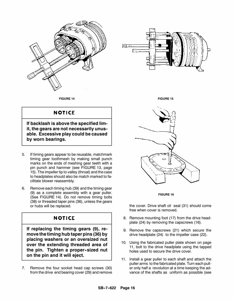
If backlash is above the specified lim-it, the gears are not necessarily unus-able. Excessive play could be causedby worn bearings.
5. If timing gears appear to be reusable, matchmarktiming gear toothmesh by making small punchmarks on the ends of meshing gear teeth with apin punch and hammer (see FIGURE 13, page15). The impeller tip to valley (throat) and the caseto headplates should also be match marked to fa-cilitate blower reassembly.
6. Remove each timing hub (39) and the timing gear(9) as a complete assembly with a gear puller.(See FIGURE 14). Do not remove timing bolts(38) or threaded taper pins (36), unless the gearsor hubs will be replaced.
If replacing the timing gears (9), re-move the timinghub taperpins (36) byplacing washers or an oversized nutover the extending threaded area ofthe pin. Tighten a proper--sized nuton the pin and it will eject.
7. Remove the four socket head cap screws (30)from the drive end bearing cover (29) and remove
FIGURE 16
the cover. Drive shaft oil seal (31) should comefree when cover is removed.
8. Remove mounting foot (17) from the drive head-plate (24) by removing the capscrews (16).
9. Remove the capscrews (21) which secure thedrive headplate (24) to the impeller case (22).
10. Using the fabricated puller plate shown on page11, bolt to the drive headplate using the tappedholes used to secure the drive cover.
11. Install a gear puller to each shaft and attach thepuller arms to the fabricated plate. Turn eachpull-er only half a revolution at a time keeping the ad-vance of the shafts as uniform as possible (see

SB--7--622 Page 17
FIGURE 17
FIGURE 15, page 16). After the headplate hasbeen removed, detach the puller plate.
12. Remove the two drive end bearings (14) from thedrive headplate (24) using a ball peen hammerand punch (see FIGURE 16, page 16).
Exercise care not to damage theheadplatebearingboreswhen remov-ing bearings.
13. Remove the drive end spacers (33), (34) and (41).Thegrease seals (15) cannowbe drivenout of thedrive headplate with hammer and punch (seeFIGURE 16, page 16). Discard the seals as theywill not be reused. Replace grease seals eachtime the headplate is removed.
Seals and bearings should be re-placed during overhaul as a matter ofservice policy.
14. Remove the four cap screws (10) which fasteneach bearing retainer (12) to the gear headplate.
15. Attach fabricated puller plate to the gear head-plate using the tapped holes used to secure thebearing retainers.
16. Install a gear puller to one of the shafts and attachthe puller arms to the fabricated plate (seeFIGURE 17).
17. Push the impeller shaft through the gear head-plate and remove the impeller assembly (23) (seeFIGURE 17). Remove the other impeller assem-bly following the same procedure.
18. Remove mounting foot (17) from the gear head-plate by removing 4 capscrews (16).
19. Remove the cap screws (21) securing the gearheadplate to the impeller case. Located near eachdowel pin on the headplate is a threaded hole. In-sert a 3/8--16 UNC capscrew into each of thethreaded holes. Tighten the screws evenly untilthe headplate separates from the impeller case.
20. Remove the two gear end bearings (14) from thegear headplate (18) as done in step 12.
21. Remove the bearing seal spacers (33) and oilseals (15) from thegear headplate as done inStep13.

SB--7--622 Page 18
SECTION 7ASSEMBLY INSTRUCTIONS
Numbers in parentheses ( ) refer tokey numbers in assembly drawingson pages 25, 27 and 29.
1. Make sure all metallic parts are clean and free ofany nicks or burrs.
2. Lubricate the outside diameter of the lip seal (15)with a light oil or grease. Install seals in both thedrive head--plate (24) and gear headplate (18).The seal lip should always face towards the bear-ing or lubricant. New seals should be installedeach time the headplate is removed.
Make sure seals are fully seated. Useextreme care when installing.
INSTALLING MECHANICAL SEALS
A. Lightly coat the headplate bores with assem-bly lubricant.
B. Refer to FIGURE 18. Install mechanical seal(A) into the headplate bore using a press andthe correct driver shown on page 13. Drivethe seal securely on to its seat.
Use extreme care when installingseals in the headplate bores. Do notattempt to install the mechanicalseals without the use of a press.Blows from a hammer or mallet candamage the fragile seal surface. Toomuch force can crush the seal casing.Make certain the seal is properlyseated and undamaged before pro-ceeding.
FIGURE 18

SB--7--622 Page 19
FIGURE 19 FIGURE 20
3. Assemble gear headplate (18) and mounting foot(17) to the impeller case with cap screws (21) andwhere the mounting foot is secured to the head-plate use capscrews (16). The two positioningdowel pins (19) will ensure proper alignment of theheadplate and impeller case. Also secure liftinglugs using capscrews (21) (see exploded assem-bly drawing page 25). Torque capscrews alter-nately and evenly. Refer to FIGURE 24, page 24,for torque specifications.
4. Apply a light oil or grease on the shaft seal areasand the bearing areas. Insert impellers into thegear headplate using the same headplate boresas used in the original assembly.
Seals are delicate; use extreme carewhen installing impeller shafts in theheadplatebores. A pieceof light shimstock wrapped around the shaft key-way will prevent cutting the seal lip.
5. Position blower so that impellers are vertical, withthe drive end on top. It will be necessary to useblocks in order for the unit to set level. Measurethe total end clearance using a depth micrometer(see FIGURE 19).
If total clearance is not within the limits specifiedin FIGURE 21, page 20, it may be necessary toshim the case to obtain the proper total end clear-ance. The shim should be placed between thedrive headplate and impeller case.
If more than .007” shim is required,put .007” on the drive end and theremaining on the gear end.
6. Assemble drive headplate (24) to impeller caseasdone in step 3 with the gear headplate. If shimswere required, place shims between drive head-plate and impeller case.
7. Insert bearing--seal spacers (34), (41) into thedrive shaft headplate bore and spacer (33) into theremaining bores (see exploded view, page 25).
MECHANICAL SEALS ONLY
A. Refer to FIGURE 18, page18. Lightly coatthe impeller shaft (H) and the inside diameterof the mating ring (B) with assemblylubricant.
B. Install themating ring (B) on the shaft only farenough to install spacer (34), (41) in the boreand allow for the bearing inner race (E) to bestarted on the shaft.

SB--7--622 Page 20
FIGURE 21
Do not drive the mating ring down tothe mechanical seal, as this can dam-age the seal.
C. Install mating ring (B) on the drive end shortshaft and the gear end shafts as done in theprevious step, but use spacer (33) (refer togear end, FIGURE 18, page 18).
D. Brush the bearing inner race (E) with a lightoil or grease.
E. Using a press and the bearing installationtool shown on page 14, install the sphericalroller bearing (35) on the drive end driveshaft. Install the three double row ball bear-ings on the remaining shaft ends. Bearingswill position the mating ring (B) to the properdepth with respect to themechanical seal (A)when the installation tool is tight against theheadplate.
8. Apply a light oil to the drive headplate bearing
bore, bearing inside diameter, and shaft seat.Install the spherical roller bearing (35) on the driveend drive shaft and the double row ball bearing(14) on the drive end driven shaft. Start the bear-ing in the bores without force.
9. Attach the puller plate shown on page 11 to thedrive headplate using the tappedholes used to se-cure the drive cover (see FIGURE 20, page 19).Tighten the bolts so that the advance of the bear-ings stay as uniform as possible. Bearings shouldbe pressed until fully seated in the bore.
Bearings will not be flush with gearheadplate bores when completelyseated.
10. Lubricate the gear end bearing fits with a light oilas described previously. Install gear end bearings(14) as far as possiblewithout force. Use the fabri-cated plate, used to install the drive end bearings,to press the bearings on the shafts as described

SB--7--622 Page 21
in Step 9. Press bearings into the gear headplateuntil completely seated in the bearing bore.
Bearings will not be flush with gearheadplate bores when completelyseated.
11. Impeller should now be checked for free axialmovement by hitting the ends of the impellershafts with the palm of your hand.
12. Push the impellers against thegear headplate andrecheck the total end clearance between the driveheadplate and the impellers (see FIGURE 21,page 20).
A. If total end clearance is insufficient, loosenimpeller case to headplate bolts on eitherheadplate, and move the headplate awayfrom the case far enough to insert a papershim in the amount equal to the insufficientclearance. Retighten case bolts and againcheck the total end clearance. Refer toFIGURE 21, page 20, for correct clearance.
B. Excessive end clearances normally willrequire new impeller assemblies, but in somecircumstances the impeller case can beremoved and reduced in width by machiningoff the amount of excess clearance.
These impeller-to-impeller and impel-ler-to-case clearances are extremelycritical. Even though the blower mayturn freely by hand when cold, underoperating conditions, the partsexpand, and the rotors are subject toslight deflection.
If the clearances are not sufficient,the impellers may contact each otheror the housing with destructiveresults. If the clearances are toogreat, the blower may not develop thepressure or airflow that is required toperform its function.
FIGURE 22
BEARING
SHAFT
GEARHEADPLATE
A
13. Impeller tip to case clearance should be checkedat this time by inserting the correct thicknessfeeler gauge between the tip and the case (B) androtating the impeller (see FIGURE 21, page 20).Repeat the procedure on both impellers.
When checking the tip to case clear-ance, move the feeler gauge over theentire length of the impeller to ensurethat the tips do not bind along theirlength.
14. Replace the drive shaft grease seal (31) in thedrive end cover (29). The seal lip should alwaysface toward the bearing or lubricant. Pack thebearing cavities with the recommended grease.
15. Secure drive cover (29) and wavy spring (28) todrive headplate using capscrews (30). Refer toFIGURE 24, page 24, for torque specifications.
Exercise care not to damage the seallip as it passes over shaft keyway.

SB--7--622 Page 22
16. SETTING IMPELLER END CLEARANCE
Refer to FIGURE 18, page 18. The gear endbearings are held in position by the force createdby the wavy spring (28) on the drive end and thebearing retainer (12) on the gear end. The inter-ference fit between the shaft (H) and the bearinginner race (E) keeps the shaft frommoving axially.
End clearance adjustment of both impellers iscontrolled by adjustment of the bearing retainer(12). Tightening the bearing retainer screws (10)moves the bearing to load the wavy spring (28),and the impeller is forced toward the drive end.Relaxing the screws allows the wavy spring to re-turn the impeller toward the gear end.
A. With impellers tight against the gear head-plate, measure the distance (A) from thebearing outer race to the gear headplate us-ing a depth micrometer (see FIGURE 22,page 21.
B. Subtract 1/3 of the total end clearance fromthe value measured at point A. This value isthe amount of shim (13) that should beplaced between the retainer and the head-plate at point (S).
C. Secure bearing retainer (12) with the correctamount of shim, to the headplate usingcapscrews (10). Torque capscrews to thespecifications given in FIGURE 24, page 24.
D. Recheck end clearances. Approximately 1/3of the total end clearance should be on thegear end and the remaining 2/3 on the driveend (refer to FIGURE 21, page 20).
If clearances require adjusting, loosen thebearingretainer capscrews (10) and insert shims to movethe impeller closer to the gear headplate andremove shims to move the impellers away fromthe gear headplate.
17. INSTALLING THE TIMING GEARS
Impellers are held in timeby gearswhich are taperpinned and bolted to a timing hub, which in turn ispressed and taper pinned onto the shaft. Thetiming gears can be rotated in relation to the hubby removing the taper pins in the web of the gearand loosening the capscrews. Because the cap-screws are oversized, the gear will rotate -- withinlimits -- relative to the timing hub when the screwsare loosened.
FIGURE 23
A. Apply a light grease, or oil, on the shaft areawhere the timing gear will be positioned.
B. Lubricate the inside diameter of spacers (32)with assembly lubricant and install on thegear end shafts.
C. Using a piece of paper large enough to coverthe open end of the gear headplate, trace theshafts on the paper and cut-out shaft holes.This will be placed on the shafts before thegears to protect the bearings from metalshavings when drilling taper pin holes in thefollowing procedure.
D. Place feeler stock in the amount of 1/3 of thetotal end clearance between drive headplateand both impellers. This will stop the impel-lers from contacting the headplate while thegears are being driven on.
If installing gears on a blowercontaining mechanical seals, a pressmust be used to drive thegears on theshafts. Blows from a hammer ormallet will damage the seal.
E. If reusing the timing gears and hubs, theyshould be returned to their original positionwith respect to the impellers.
If replacement gears are used, secure eachgear (9) to its timing hub (39) with capscrews(38) and lockwasher (37) and tighten slightly.

SB--7--622 Page 23
Replacement gears have minimumbacklashmarkson theoutsidediame-ter of the gear face. These marksshould be located 180 degrees fromeach other (see FIGURE 23).
F. Position impellers so they are 90 degrees toeach other. Using the driving tool shown onpage 12, install the gears and hubs on theshafts using the taper pin holes and matchmarks for correct positioning. Check to besure impellers are in correct position as pre-viously match marked.
Utilize a press whenever possiblewhen installing gears.
G. Refer to diagram in FIGURE 21, page 20.Use feeler gauges to check clearancesbetween impeller lobes at positions A--A andC--C. Add the clearances, anddivide the totalclearance evenly between A--A and C--C.
H. Loosen the four capscrews (38) in one gearonly. Wedge the correct amount of feelergauge between the impeller at A--A. If move-ment between the gear and hub is not suffi-cient to time the impellers, it will be neces-sary to loosen the four capscrews (38) in themating gear to obtain a large adjustmentrange. Adjust so that the clearance at A--Ais equal to C--C within .001 inch.
Clearances must be checked on both sidesof each impeller lobe over the entire length.This procedure may require repeating sever-al times until impeller lobe clearance is equalon both sides.
I. Secure the timing gears (9) to the hubs (39)with capscrews (38) and lockwasher (37).Tighten capscrews to the torque specifica-tion listed in FIGURE 24, page 24.
J. Check gear backlash four places at 90degree intervals as described in the disas-sembly procedure (Item 4).
If any of the four gear backlash read-ings are not within the specifiedlimits, the gears must be replaced.
K. Reream taper pin hole between the shaft andhubwith a hand reamer and replace taper pin(8) if movement between the shaft and hub(39) was negligible. If rereaming fails to elim-inate edges due to slight misalignment, drilland ream a new hole approximately 90degrees from the original hole. Control thedepth of the taper pin, leaving approximately1/8” taper pin protruding beyond the hub andshaft.
L. Reream center drilled hole in the hub andgear web. If rereaming fails to eliminateedges set up by retiming, ream hole for thenext larger taper pin or drill and ream a newhole approximately 90 degrees from theorig-inal hole. Control the depth of the threadedtaper pin (36), leaving the threaded portion ofthe pin protruded beyond the hub.
Replacement gears are not drilled for taperpin (8). These holes must be drilled andreamed after the gears are in proper positionand the unit retimed.
Be careful not to allow cuttings todrop behind the gears and contami-nate the bearings.
M. Remove paper from behind the gears. Makecertain metal cuttings did not contaminatethe bearings.
18. Assemble gear cover (3) and gasket (7) to thegear headplate (18) using capscrews (5). Tightencapscrews alternately and evenly. Refer toFIGURE 24, page 24 for torque specifications.
19. Place blower on its feet on a flat surface. Loosencapscrews (16) and level unit up. The bench orblower base flatness should be within .002 of aninch. Re-tighten cap screws (16) to the specifica-tions in FIGURE 24, page 24.
SB--7--622 Page 24
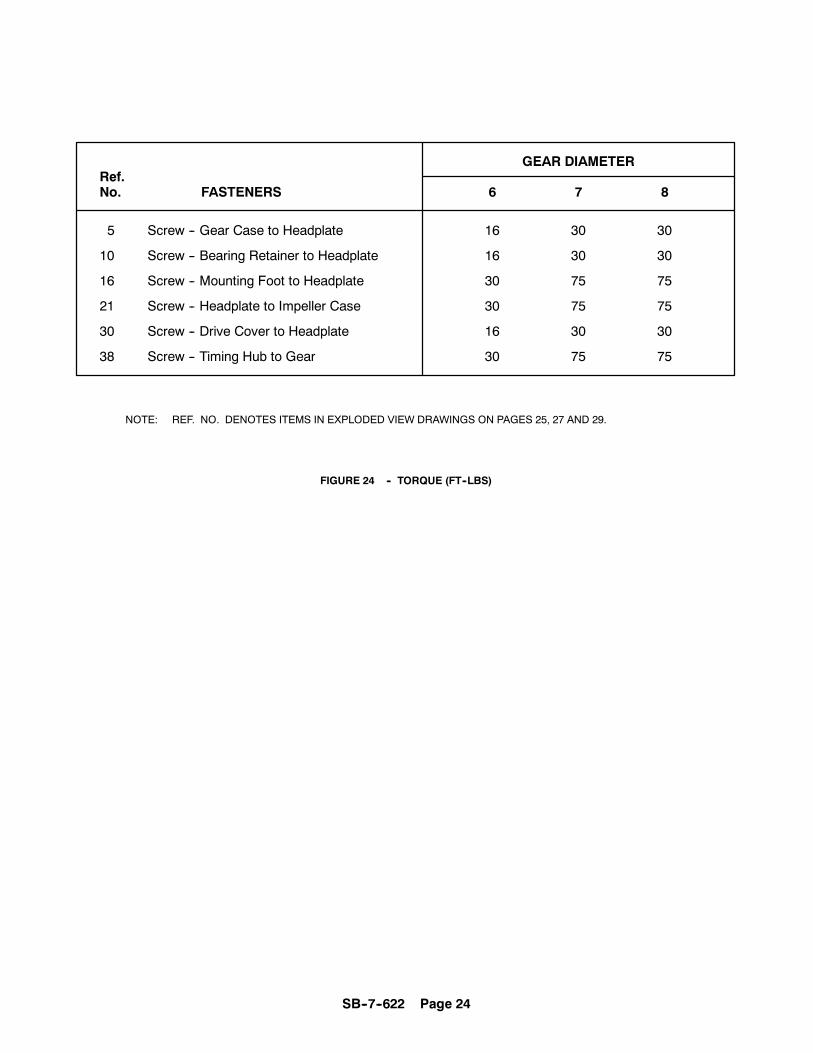
GEAR DIAMETERRef.No. FASTENERS 6 7 8
5 Screw -- Gear Case to Headplate 16 30 30
10 Screw -- Bearing Retainer to Headplate 16 30 30
16 Screw -- Mounting Foot to Headplate 30 75 75
21 Screw -- Headplate to Impeller Case 30 75 75
30 Screw -- Drive Cover to Headplate 16 30 30
38 Screw -- Timing Hub to Gear 30 75 75
NOTE: REF. NO. DENOTES ITEMS IN EXPLODED VIEW DRAWINGS ON PAGES 25, 27 AND 29.
FIGURE 24 -- TORQUE (FT--LBS)

SB--7--622 Page 25
SECTION 8PARTS LIST
300GAF810--B(Ref. Drawing)

SB--7--622 Page 26
Order by Part Number and Description. Reference Numbers are for your convenience only.
MODEL GAF
Ref. No. Size -- 6H Size -- 6M Size -- 6LNo. Description Req’d GAFH_P_ GAFM_P_ GAFL_P_
1 NAMEPLATE 1 301GAE496 301GAE496 301GAE496. . . . . . . . . . . . . . . . . . . . . . . . . . . . . . . . . . . . . . . . .2 PLUG FOR ALTERNATE OIL LEVEL CONN. 1 64AC4 64AC4 64AC4. . . . . . . . . . . . . .3 GEAR CASE 1 900883064201 900883064201 900883064201. . . . . . . . . . . . . . . . . . . . . . . . . . . . . . . . . . . . . . . . .4 DRAIN PLUG 1 64AC4 64AC4 64AC4. . . . . . . . . . . . . . . . . . . . . . . . . . . . . . . . . . . . . . . .5 SCREW--GEAR CASE TO HEADPLATE 12 75LM113 75LM113 75LM113. . . . . . . . . . . . . . . . . .6 BREATHER 1 5L223 5L223 5L223. . . . . . . . . . . . . . . . . . . . . . . . . . . . . . . . . . . . . . . . . .
Ø 7 GASKET GEAR CASE 1 200GAF715 200GAF715 200GAF715. . . . . . . . . . . . . . . . . . . . . . . . . . . . . . . . .Ø 8 TAPER PIN 2 62V59 62V59 62V59. . . . . . . . . . . . . . . . . . . . . . . . . . . . . . . . . . . . . . . . . .
9 TIMING GEAR GROUP 1 200GAF6008 200GAF6008 200GAF6008. . . . . . . . . . . . . . . . . . . . . . . . . . . . . . . .Ø 10 SCREW--BEARING RETAINER TO HEADPLATE 8 75A33N 75A33N 75A33N. . . . . . . . . .
12 BEARING RETAINER 2 900883065501 900883065501 900883065501. . . . . . . . . . . . . . . . . . . . . . . . . . . . . . . . .Ø 13 SHIM SET 1 900881065400 900881065400 900881065400. . . . . . . . . . . . . . . . . . . . . . . . . . . . . . . . . . . . . . . . . . .Ø 14 BEARING 3 900639080506 900639080506 900639080506. . . . . . . . . . . . . . . . . . . . . . . . . . . . . . . . . . . . . . . . . . . .
Ø 15 MAIN SEAL--PER APPLICATION BELOWMECHANICAL SEAL VERSION 4 900871020006 900871020006 900871020006. . . . . . . . . . . . . . . . . . . . . .LIP SEAL VERSION 4 60DD657 60DD657 60DD657. . . . . . . . . . . . . . . . . . . . . . . . . . . . . . . .
16 SCREW--FOOT TO HEADPLATE 8 655ED060 655ED060 655ED060. . . . . . . . . . . . . . . . . . . . . . . .17 FOOT GROUP
VERTICAL FOOT GROUP 1 GAF81950 GAF81950 GAF81950. . . . . . . . . . . . . . . . . . . . . . . . . .HORIZONTAL FOOT GROUP 1 GAF81951 GAF81951 GAF81951. . . . . . . . . . . . . . . . . . . . . . .
18 HOUSING--BEARING (GEAR END) . . . . . . . . . . . . . . . . . . . . .LIP SEAL 1 900883064401 90088364401 900883064401. . . . . . . . . . . . . . . . . . . . . . . . . . . . . . . . . . . . . . . . .MECHANICAL SEAL 1 900883064501 90088364501 900883064501. . . . . . . . . . . . . . . . . . . . . . . . . . . . . . .
19 DOWEL PIN 4 62M48 62M48 62M48. . . . . . . . . . . . . . . . . . . . . . . . . . . . . . . . . . . . . . . . .20 LIFTING LUG 2 200GAF451 200GAF451 200GAF451. . . . . . . . . . . . . . . . . . . . . . . . . . . . . . . . . . . . . . . .21 SCREW--HEADPLATES TO IMPELLER CASE 24 655ED050 655ED050 655ED050. . . . . . . . . . . .22 IMPELLER CASE 1 900883063901 900883064001 900883064101. . . . . . . . . . . . . . . . . . . . . . . . . . . . . . . . . . . . .
23 SHAFT ASSEMBLY GROUP 1 GAF81952 GAF81954 GAF81953. . . . . . . . . . . . . . . . . . . . . . . . . . .SHAFT ASSEMBLY GROUP CONSISTS OF:
(1) ASSEMBLY SHAFT -- LONG(1) ASSEMBLY SHAFT -- SHORT
24 HOUSING--BEARING (DRIVE END)LIP SEAL 1 900883064901 900883064901 900883064901. . . . . . . . . . . . . . . . . . . . . . . . . . . . . . . . . . . . . . . . .MECHANICAL SEAL 1 900883064801 900883064801 900883064801. . . . . . . . . . . . . . . . . . . . . . . . . . . . . . .
25 DRIVE KEY 1 900639910406 900639910406 900639910406. . . . . . . . . . . . . . . . . . . . . . . . . . . . . . . . . . . . . . . . . .26 GREASE FITTING 2 911659990606 911659990606 911659990606. . . . . . . . . . . . . . . . . . . . . . . . . . . . . . . . . . . .27 GREASE FITTING CAP 2 40P41 40P41 40P41. . . . . . . . . . . . . . . . . . . . . . . . . . . . . . . .28 WAVY SPRING 2 900669170506 900669170506 900669170506. . . . . . . . . . . . . . . . . . . . . . . . . . . . . . . . . . . . . . .29 DRIVE COVER 1 900883064601 900883064601 900883064601. . . . . . . . . . . . . . . . . . . . . . . . . . . . . . . . . . . . . . .30 SCREW--DRIVE COVER TO HEADPLATE 8 75LM113 75LM113 75LM113. . . . . . . . . . . . . . . .
Ø 31 DRIVE SEAL 1 60DD658 60DD658 60DD658. . . . . . . . . . . . . . . . . . . . . . . . . . . . . . . . . . . . . . . . .32 SPACER--GEAR END 2 900811060401 900811060401 900811060401. . . . . . . . . . . . . . . . . . . . . . . . . . . . . . . . .33 SPACER--GEAR & DRIVE END--SEAL/BRG 3 900881066201 900881066201 900881066201. . . . . . . . . . . . . .34 SPACER--DRIVE END DRIVE SHAFT--SEAL/BRG 1 900881066401 900881066401 900881066401. . . . . . . . .
Ø 35 BEARING--DRIVE END DRIVE SHAFT 1 900811060801 900811060801 900811060801. . . . . . . . . . . . . . . . . . .36 THREADED TAPER PIN 2 62V67 62V67 62V67. . . . . . . . . . . . . . . . . . . . . . . . . . . . . . .37 WASHER--GEAR 8 900649440205 900649440205 900649440205. . . . . . . . . . . . . . . . . . . . . . . . . . . . . . . . . . . . .38 SCREW--TIMING HUB TO GEAR 8 655ED060 655ED060 655ED060. . . . . . . . . . . . . . . . . . . . . . .39 HUB--TIMING 2 900713060101 900713060101 900713060101. . . . . . . . . . . . . . . . . . . . . . . . . . . . . . . . . . . . . . . .40 GAUGE--OIL LEVEL 1 40P31 40P31 40P31. . . . . . . . . . . . . . . . . . . . . . . . . . . . . . . . . . .
* 41 SPACER--DRIVE END DRIVE SHAFT--HD PLT--BRG 1 900881066301 900881066301 900881066301. . . . . .REQUIRED WITH MECHANICAL SEAL UNITS
* 42 PLUGS REQUIRED WITH MECHANICAL SEAL UNITS 8 64AC2 64AC2 64AC2. . . .44 SCREW--SET 4 76F92 76F92 76F92. . . . . . . . . . . . . . . . . . . . . . . . . . . . . . . . . . . . . . . .
Ø OVERHAUL KIT LIP SEAL 0 203GAF6010 203GAF6010 203GAF6010. . . . . . . . . . . . . . . . . . . . . . . . . . . . .Ø OVERHAUL KIT MECHANICAL SEAL 0 204GAF6010 204GAF6010 204GAF6010. . . . . . . . . . . . . . . . . . .
* NOT SHOWNØ INCLUDED IN OVERHAUL KIT.

SB--7--622 Page 27
300GAG810--A(Ref. Drawing)

SB--7--622 Page 28
Order by Part Number and Description. Reference Numbers are for your convenience only.
MODEL GAG
Ref. No. Size -- 7H Size -- 7M Size -- 7LNo. Description Req’d GAGH_P_ GAGM_P_ GAGL_P_
1 NAMEPLATE 1 301GAE496 301GAE496 301GAE496. . . . . . . . . . . . . . . . . . . . . . . . . . . . . . . . . . . . . . . . .2 PLUG FOR ALTERNATE OIL LEVEL CONN. 1 64B4 64B4 64B4. . . . . . . . . . . . . .3 GEAR CASE 1 900893071701 900893071701 900893071701. . . . . . . . . . . . . . . . . . . . . . . . . . . . . . . . . . . . . . . . .4 DRAIN PLUG 1 64AC6 64AC6 64AC6. . . . . . . . . . . . . . . . . . . . . . . . . . . . . . . . . . . . . . . .5 SCREW--GEAR CASE TO HEADPLATE 12 75LM122 75LM122 75LM122. . . . . . . . . . . . . . . . . .6 BREATHER 1 5L223 5L223 5L223. . . . . . . . . . . . . . . . . . . . . . . . . . . . . . . . . . . . . . . . . .
Ø 7 GASKET GEAR CASE 1 200GAG715 200GAG715 200GAG715. . . . . . . . . . . . . . . . . . . . . . . . . . . . . . . . .Ø 8 TAPER PIN 2 62V60 62V60 62V60. . . . . . . . . . . . . . . . . . . . . . . . . . . . . . . . . . . . . . . . . .
9 TIMING GEAR GROUP 1 200GAG6008 200GAG6008 200GAG6008. . . . . . . . . . . . . . . . . . . . . . . . . . . . . . . .Ø 10 SCREW--BEARING RETAINER TO HEADPLATE 8 655ED040N 655ED040N 655ED040N. . . . . . . . . .
12 BEARING RETAINER 2 900893070401 900893070401 900893070401. . . . . . . . . . . . . . . . . . . . . . . . . . . . . . . . .Ø 13 SHIM SET 1 900891073800 900891073800 900891073800. . . . . . . . . . . . . . . . . . . . . . . . . . . . . . . . . . . . . . . . . . .Ø 14 BEARING 3 DF138116 DF138116 DF138116. . . . . . . . . . . . . . . . . . . . . . . . . . . . . . . . . . . . . . . . . . . .
Ø 15 MAIN SEAL--PER APPLICATION BELOWMECHANICAL SEAL VERSION 4 900871020007 900871020007 900871020007. . . . . . . . . . . . . . . . . . . . . .LIP SEAL VERSION 4 60DD715 60DD715 60DD715. . . . . . . . . . . . . . . . . . . . . . . . . . . . . . . .
16 SCREW--FOOT TO HEADPLATE 8 655EE070 655EE070 655EE070. . . . . . . . . . . . . . . . . . . . . . . .17 FOOT GROUP
VERTICAL FOOT GROUP 1 GAG81958 GAG81958 GAG81958. . . . . . . . . . . . . . . . . . . . . . . . . .HORIZONTAL FOOT GROUP 1 GAG81959 GAG81959 GAG81959. . . . . . . . . . . . . . . . . . . . . . .
18 HOUSING--BEARING (GEAR END) . . . . . . . . . . . . . . . . . . . . .LIP SEAL 1 900893072801 900893072801 900893072801. . . . . . . . . . . . . . . . . . . . . . . . . . . . . . . . . . . . . . . . .MECHANICAL SEAL 1 200GAG006 200GAG006 200GAG006. . . . . . . . . . . . . . . . . . . . . . . . . . . . . . .
19 DOWEL PIN 4 62M48 62M48 62M48. . . . . . . . . . . . . . . . . . . . . . . . . . . . . . . . . . . . . . . . .20 LIFTING LUG 2 200GAF451 200GAF451 200GAF451. . . . . . . . . . . . . . . . . . . . . . . . . . . . . . . . . . . . . . . .21 SCREW--HEADPLATES TO IMPELLER CASE 24 655EE050 655EE050 655EE050. . . . . . . . . . . .22 IMPELLER CASE 1 900893070101 900893070201 900893070301. . . . . . . . . . . . . . . . . . . . . . . . . . . . . . . . . . . . .
23 SHAFT ASSEMBLY GROUP 1 GAG81960 GAG81962 GAG81961. . . . . . . . . . . . . . . . . . . . . . . . . . .SHAFT ASSEMBLY GROUP CONSISTS OF:
(1) ASSEMBLY SHAFT -- LONG(1) ASSEMBLY SHAFT -- SHORT
24 HOUSING--BEARING (DRIVE END)LIP SEAL 1 900893070601 900893070601 900893070601. . . . . . . . . . . . . . . . . . . . . . . . . . . . . . . . . . . . . . . . .MECHANICAL SEAL 1 900893072601 900893072601 900893072601. . . . . . . . . . . . . . . . . . . . . . . . . . . . . . .
25 DRIVE KEY 1 900639910407 900639910407 900639910407. . . . . . . . . . . . . . . . . . . . . . . . . . . . . . . . . . . . . . . . . .26 GREASE FITTING 2 911659990606 911659990606 911659990606. . . . . . . . . . . . . . . . . . . . . . . . . . . . . . . . . . . .27 GREASE FITTING CAP 2 40P41 40P41 40P41. . . . . . . . . . . . . . . . . . . . . . . . . . . . . . . .28 WAVY SPRING 2 900669170607 900669170607 900669170607. . . . . . . . . . . . . . . . . . . . . . . . . . . . . . . . . . . . . . .29 DRIVE COVER 1 900883073701 900883073701 900883073701. . . . . . . . . . . . . . . . . . . . . . . . . . . . . . . . . . . . . . .30 SCREW--DRIVE COVER TO HEADPLATE 8 75LM122 75LM122 75LM122. . . . . . . . . . . . . . . .
Ø 31 DRIVE SEAL 1 60DD727 60DD727 60DD727. . . . . . . . . . . . . . . . . . . . . . . . . . . . . . . . . . . . . . . . .32 SPACER--GEAR END 2 900891073001 900891073001 900891073001. . . . . . . . . . . . . . . . . . . . . . . . . . . . . . . . .33 SPACER--GEAR & DRIVE END--SEAL/BRG 3 200GAG144 200GAG144 200GAG144. . . . . . . . . . . . . .34 SPACER--DRIVE END DRIVE SHAFT--SEAL/BRG 1 201GAG144 201GAG144 201GAG144. . . . . . . . .
Ø 35 BEARING--DRIVE END DRIVE SHAFT 1 910712068201 910712068201 910712068201. . . . . . . . . . . . . . . . . . .36 THREADED TAPER PIN 2 62V68 62V68 62V68. . . . . . . . . . . . . . . . . . . . . . . . . . . . . . .37 WASHER--GEAR 8 900649440507 900649440507 900649440507. . . . . . . . . . . . . . . . . . . . . . . . . . . . . . . . . . . . .38 SCREW--TIMING HUB TO GEAR 8 655EE060 655EE060 655EE060. . . . . . . . . . . . . . . . . . . . . . .39 HUB--TIMING 2 900713060102 900713060102 900713060102. . . . . . . . . . . . . . . . . . . . . . . . . . . . . . . . . . . . . . . .40 GAUGE--OIL LEVEL 1 VP1004935 VP1004935 VP1004935. . . . . . . . . . . . . . . . . . . . . . . . . . . . . . . . . . .
* 41 SPACER--DRIVE END DRIVE SHAFT--HD PLT--BRG 1 900881073301 900881073301 900881073301. . . . . .REQUIRED WITH MECHANICAL SEAL UNITS
* 42 PLUGS REQ. W/MECH. SEAL UNITS(GEAR END) 4 64AC3 64AC3 64AC3. . . . . . . .* 46 PLUGS REQ. W/MECH. SEAL UNITS (DRIVE END) 4 64AC2 64AC2 64AC2. . . . . . .
Ø OVERHAUL KIT LIP SEAL 0 200GAG6010 200GAG6010 200GAG6010. . . . . . . . . . . . . . . . . . . . . . . . . . . . . . . . . . .Ø OVERHAUL KIT MECHANICAL SEAL 0 201GAG6010 201GAG6010 201GAG6010. . . . . . . . . . . . . . . . . . . . . . . . . .
* NOT SHOWNØ INCLUDED IN OVERHAUL KIT.

SB--7--622 Page 29
300GAH810--A(Ref. Drawing)

SB--7--622 Page 30
Order by Part Number and Description. Reference Numbers are for your convenience only.
MODEL GAHRef. No. Size -- 8H Size -- 8M Size -- 8LNo. Description Req’d GAHH_P_ GAHM_P_ GAHL_P_
1 NAMEPLATE 1 301GAE496 301GAE496 301GAE496. . . . . . . . . . . . . . . . . . . . . . . . . . . . . . . . . . . . . . . . .2 PLUG FOR ALTERNATE OIL LEVEL CONN. 1 64AC5 64AC5 64AC5. . . . . . . . . . . . . .3 GEAR CASE 1 900893082501 900893082501 900893082501. . . . . . . . . . . . . . . . . . . . . . . . . . . . . . . . . . . . . . . . .4 DRAIN PLUG 1 64AC5 64AC5 64AC5. . . . . . . . . . . . . . . . . . . . . . . . . . . . . . . . . . . . . . . .5 SCREW--GEAR CASE TO HEADPLATE 12 2009649 2009649 2009649. . . . . . . . . . . . . . . . . .6 BREATHER 1 5L223 5L223 5L223. . . . . . . . . . . . . . . . . . . . . . . . . . . . . . . . . . . . . . . . . .
Ø 7 GASKET GEAR CASE 1 200GAH715 200GAH715 200GAH715. . . . . . . . . . . . . . . . . . . . . . . . . . . . . . . . .Ø 8 TAPER PIN 2 62V61 62V61 62V61. . . . . . . . . . . . . . . . . . . . . . . . . . . . . . . . . . . . . . . . . .
9 TIMING GEAR GROUP 1 200GAH6008 200GAH6008 200GAH6008. . . . . . . . . . . . . . . . . . . . . . . . . . . . . . . .10 SCREW--BEARING RETAINER TO HEADPLATE 8 655ED04N 655ED04N 655ED04N. . . . . . . . . .11 LOCKWASHER 8 95B3 95B3 95B3. . . . . . . . . . . . . . . . . . . . . . . . . . . . . . . . . . . . . . .12 BEARING RETAINER 2 900893083101 900893083101 900893083101. . . . . . . . . . . . . . . . . . . . . . . . . . . . . . . . .
Ø 13 SHIM SET 1 910639630008 910639630008 910639630008. . . . . . . . . . . . . . . . . . . . . . . . . . . . . . . . . . . . . . . . . . .Ø 14 BEARING 3 900639080808 900639080808 900639080808. . . . . . . . . . . . . . . . . . . . . . . . . . . . . . . . . . . . . . . . . . . .Ø 15 MAIN SEAL--PER APPLICATION BELOW
MECHANICAL SEAL VERSION 4 900871020008 900871020008 900871020008. . . . . . . . . . . . . . . . . . . . . .LIP SEAL VERSION 4 910751061902 910751061902 910751061902. . . . . . . . . . . . . . . . . . . . . . . . . . . . . . . .
16 SCREW--FOOT TO HEADPLATE 8 655EE080 655EE080 655EE080. . . . . . . . . . . . . . . . . . . . . . . .17 FOOT GROUP
VERTICAL FOOT GROUP 1 GAH81966 GAH81966 GAH81966. . . . . . . . . . . . . . . . . . . . . . . . . .HORIZONTAL FOOT GROUP 1 GAH81967 GAH81967 GAH81967. . . . . . . . . . . . . . . . . . . . . . .
18 HOUSING--BEARING (GEAR END) . . . . . . . . . . . . . . . . . . . . .LIP SEAL 1 900894082301 900894082301 900894082301. . . . . . . . . . . . . . . . . . . . . . . . . . . . . . . . . . . . . . . . . .MECHANICAL 1 200GAH006 200GAH006 200GAH006. . . . . . . . . . . . . . . . . . . . . . . . . . . . . . . . . . . . . . .
19 DOWEL PIN 4 62M48 62M48 62M48. . . . . . . . . . . . . . . . . . . . . . . . . . . . . . . . . . . . . . . . .20 LIFTING LUG 2 200GAF451 200GAF451 200GAF451. . . . . . . . . . . . . . . . . . . . . . . . . . . . . . . . . . . . . . . .21 SCREW--HEADPLATES TO IMPELLER CASE 36 655EE060 655EE060 655EE060. . . . . . . . . . . .22 IMPELLER CASE 1 900653021708 910613746808 910613747008. . . . . . . . . . . . . . . . . . . . . . . . . . . . . . . . . . . . .23 SHAFT ASSEMBLY GROUP 1 GAH81968 GAH81970 GAH81969. . . . . . . . . . . . . . . . . . . . . . . . . . .
SHAFT ASSEMBLY GROUP CONSISTS OF:(1) ASSEMBLY SHAFT -- LONG(1) ASSEMBLY SHAFT -- SHORT
24 HOUSING--BEARING (DRIVE END)LIP SEAL 1 900894082101 900894082101 900894082101. . . . . . . . . . . . . . . . . . . . . . . . . . . . . . . . . . . . . . . . .MECHANICAL SEAL 1 201GAH006 201GAH006 201GAH006. . . . . . . . . . . . . . . . . . . . . . . . . . . . . . .
25 DRIVE KEY 1 900639910407 900639910407 900639910407. . . . . . . . . . . . . . . . . . . . . . . . . . . . . . . . . . . . . . . . . .26 GREASE FITTING 2 911659990606 911659990606 911659990606. . . . . . . . . . . . . . . . . . . . . . . . . . . . . . . . . . . .27 GREASE FITTING CAP 2 40P41 40P41 40P41. . . . . . . . . . . . . . . . . . . . . . . . . . . . . . . .28 WAVY SPRING 2 900669170708 900669170708 900669170708. . . . . . . . . . . . . . . . . . . . . . . . . . . . . . . . . . . . . . .29 DRIVE COVER 1 900693086301 900693086301 900693086301. . . . . . . . . . . . . . . . . . . . . . . . . . . . . . . . . . . . . . .30 SCREW--DRIVE COVER TO HEADPLATE 8 655ED030 655ED030 655ED030. . . . . . . . . . . . . . . .
Ø 31 DRIVE SEAL 1 60DD676 60DD676 60DD676. . . . . . . . . . . . . . . . . . . . . . . . . . . . . . . . . . . . . . . . .32 SPACER--GEAR END 2 900811060403 900811060403 900811060403. . . . . . . . . . . . . . . . . . . . . . . . . . . . . . . . .33 SPACER--GEAR & DRIVE END -- SEAL/BRG 3 900871060803 900871060803 900871060803. . . . . . . . . . . . .34 SPACER--DRIVE END DRIVE SHAFT--SEAL/BRG 1 202GAH144 202GAH144 202GAH144. . . . . . . . .
Ø 35 BEARING--DRIVE END DRIVE SHAFT 1 910721070501 910721070501 910721070501. . . . . . . . . . . . . . . . . . .36 THREADED TAPER PIN 2 62V69 62V69 62V69. . . . . . . . . . . . . . . . . . . . . . . . . . . . . . .37 WASHER--GEAR 8 900649440507 900649440507 900649440507. . . . . . . . . . . . . . . . . . . . . . . . . . . . . . . . . . . . .38 SCREW--TIMING HUB TO GEAR 8 655EE080 655EE080 655EE080. . . . . . . . . . . . . . . . . . . . . . .39 HUB--TIMING 2 900713060103 900713060103 900713060103. . . . . . . . . . . . . . . . . . . . . . . . . . . . . . . . . . . . . . . .40 GAUGE--OIL LEVEL 1 40P45 40P45 40P45. . . . . . . . . . . . . . . . . . . . . . . . . . . . . . . . . . .
* 41 SPACER--DRIVE END DRIVE SHAFT--HD PLT--BRG 1 900881082401 900881082401 900881082401. . . . . .REQUIRED WITH MECHANICAL SEAL UNITS
* 42 PLUGS REQUIRED WITH MECHANICAL SEAL UNITS 8 64AC3 64AC3 64AC3. . . .43 DRIVEN COVER 1 900693086401 900693086401 900693086401. . . . . . . . . . . . . . . . . . . . . . . . . . . . . . . . . . . . . .
Ø OVERHAUL KIT LIP SEAL 0 GAH81972 GAH81972 GAH81972. . . . . . . . . . . . . . . . . . . . . . . . . . . . . . . . . . .Ø OVERHAUL KIT MECHANICAL SEAL 0 GAH81971 GAH81971 GAH81971. . . . . . . . . . . . . . . . . . . . . . . . . .
* NOT SHOWNØ INCLUDED IN OVERHAUL KIT.
GENERAL PROVISIONS AND LIMITATIONS
GardnerDenver (the “Company”) warrants to eachorig-inal retail purchaser (“Purchaser”) of its new productsfrom theCompany or its authorized distributor that suchproducts are, at the time of delivery to the Purchaser,madewith goodmaterial andworkmanship. Nowarran-ty is made with respect to:
1. Any product which has been repaired or alteredin such a way, in the Company’s judgment, asto affect the product adversely.
2. Any product which has, in the Company’s judg-ment been subject to negligence, accident,improper storage, or improper installation orapplication.
3. Any product which has not been operated ormaintained in accordance with normal practiceand with the recommendations of the Company.
4. Components or accessories manufactured,warranted and serviced by others.
5. Any reconditioned or prior owned product.
Claims for items described in (4) above should besubmitted directly to the manufacturer.
WARRANTY PERIOD
The Company’s obligation under this warranty is limitedto repairing or, at its option, replacing, during normalbusiness hours at an authorized service facility of theCompany, any part which in its judgment proved not tobe as warranted within the applicable Warranty Periodas follows.
BARE BLOWERS
Basic bare blowers, consisting of all parts within, arewarranted for 18 months from date of initial use or 24months from date of shipment to the first purchaser,whichever occurs first.
Any disassembly or partial disassembly of the blower,or failure to return the “unopened” blower per Companyinstructions, will be cause for denial of warranty.
OTHER COMPONENTS
All other components are warranted for 12 months fromdate of initial use or 18 months from date of shipmentto first purchaser, whichever comes first.
TheCompany reserves the right towithdraw theUncon-tested Warranty where evidence indicates applicationoutside the stated performance area, or where there isevidence of abuse
LABOR TRANSPORTATION AND INSPECTION
TheCompany will provide labor, by Company represen-tative or authorized service personnel, for repair orreplacement of any product or part thereof which in the
Company’s judgment is proved not to be as warranted.Labor shall be limited to the amount specified in theCompany’s labor rate schedule.
Labor costs in excess of the Company rate scheduleamounts or labor provided by unauthorized servicepersonnel is not provided for by this warranty.
Transportation of Company’s choice, within the conti-nental United States, is covered by this warranty forreplacement of any blower which in the Company’sjudgement proved not to be as warranted. For userlocations outside the continental United States, theCompany will provide transportation, by the carrier of itschoice to and from the nearest Authorized Distributorand the Company’s designated facility. The Companymay require the return of any blower claimed not to beas warranted to one of its facilities as designated by theCompany, transportation prepaid by Purchaser, toestablish a claim under this warranty.
Replacement parts provided under the terms of thewarranty are warranted for the remainder of theWarrantyPeriod of the product upon which installed to the sameextent as if such parts were original components thereof.
DISCLAIMER
THE FOREGOING WARRANTY IS EXCLUSIVE ANDIT IS EXPRESSLY AGREED THAT, EXCEPT AS TOTITLE, THE COMPANY MAKES NO OTHER WAR-RANTIES, EXPRESSED, IMPLIED OR STATUTORY,INCLUDING ANY IMPLIED WARRANTY OFMERCHANTABILITY.
THE REMEDY PROVIDED UNDER THIS WARRAN-TY SHALL BE THE SOLE, EXCLUSIVE AND ONLYREMEDY AVAILABLE TO PURCHASER AND IN NOCASE SHALL THE COMPANY BE SUBJECT TO ANYOTHER OBLIGATIONS OR LIABILITIES. UNDERNOCIRCUMSTANCES SHALL THE COMPANY BELIABLE FOR SPECIAL, INDIRECT, INCIDENTAL ORCONSEQUENTIAL DAMAGES, EXPENSES,LOSSES OR DELAYS HOWSOEVER CAUSED.
No statement, representation, agreement, or under-standing, oral or written, made by any agent, distributor,representative, or employee of the Company which isnot contained in this Warranty will be binding upon theCompany unless made in writing and executed by anofficer of the Company.
This warranty shall not be effective as to any claimwhich is not presented within 30 days after the dateupon which the product is claimed not to have been aswarranted. Any action for breach of this warranty mustbe commenced within one year after the date uponwhich the cause of action occurred.
Any adjustment made pursuant to this warranty shallnot be construed as an admission by the Company thatany product was not as warranted.
WARRANTY
SUTORBILT BLOWERS
SUTORBILT LEGEND SERIES
COPYRIGHT 2005 Gardner Denver, Inc.
