legrand cable lighting & data trunking technical
DESCRIPTION
cable trunking catalogueTRANSCRIPT

2003/04CABLE MANAGEMENT SOLUTIONS CATALOGUE
www.legrand.co.ukwww.legrand.co.uk
Distributor :
LEGRAND ELECTRIC LIMITEDDial Lane, West Bromwich, West Midlands, B70 0EB
Customer Services : Tel : 0845 605 4333 Fax : 0845 605 4334E-mail : [email protected]
Technical : Tel : 0845 605 5333 Fax : 0845 605 5334E-mail : [email protected]
DISTRIBUTION CENTRES
1. Glasgow Tel : 0141 764 2200Fax : 0141 764 2201
2. LeedsTel : 0113 233 9950Fax : 0113 233 9964
3. BirminghamTel : 0845 605 4333Fax : 0845 605 4334
4. LondonTel : 01895 458777Fax : 01895 458778
E-mail : [email protected]
D L PASS, Fastrack, Rolfe King, Salamandre, Swifts and the Legrand logo are registered trademarks of theLegrand group of companies.
Mosaic is a trademark of the Legrand group of companies.
CA
BM
AN
07.
2003
.30K
1
2
3
4
2003
/ 04
CA
BL
E M
AN
AG
EM
EN
T S
OL
UT
ION
S C
ATA
LO
GU
E
A COMPLETE CABLE MANAGEMENT SOLUTION FOR COMMERCIAL AND INDUSTRIAL APPLICATIONS
®
®

CABLE TRUNKING
Sala
mandre
METALSURFACETRUNKINGSYSTEMS
100
The Salamandre range of
surface trunking, available in
single and multi-compartment
options, is ideal for meeting the
requirements of all types of
installations and environments.

cable
tru
nk
ing s
yst
em
101
www.legrand.co.uk
CABLE TRUNKING
A variety of fixing methods forfaster and safer installation...screws, tamper-proof screws
and 900 turnbuckles
As an alternative finish,powder coated white RAL
9003 trunking offers lowsmoke and fume emissions
In addition to standardgalvanised and painted
options, a range of IP ratedand stainless steel finishes
are also available

cable trunking systemstandard trunking
ORDERING INFORMATIONTRUNKING SIZE CODES
size in mmWide x Deep
SIZECODE
50 x75 x75 x
100 x100 x100 x150 x150 x150 x150 x
50507550751005075100150
22323342434462636466
size in mmWide x Deep
SIZECODE
225 x225 x225 x225 x225 x300 x300 x300 x300 x300 x300 x
50751001502255075100150225300
9293949699
122123124126129
1212
TRUNKING LENGTHSLid Fixing To complete the reference, add the trunking
SIZE code given in the table (above).
EXAMPLE:For 75x50 Single Compartment PowderCoated Trunking, with Plastic TurnbuckleFix Lid:- MG32P
The trunking SIZE code should be includedin the component reference where indicated.
FinishesPre-galvanized
Plastic turnbuckleDie-cast turnbuckleScrew fixTamperproof screw fix
MG SIZE NMGD SIZEMS SIZEMST SIZE
Powder coated
MG SIZE PMGD SIZE PMS SIZE PMST SIZE P
COMPONENT REFERENCESComponent references are given for pre-galvanized finish with plastic turnbuckle fix lid.References for finishes and lid fixings are given below.
Each Trunking length is supplied with connector, lidand lid fixings.
Screw fix lids are supplied fitted with pozi pan headBZP screws as standard.
Tamperproof screw fix lids are supplied fitted withmild steel plated screws with TORX® screws baggedseparately for fitting when installation is complete.
Trunking Lengths - 3m
Single Compartment
50 x 50 MG22N
75 x 50 MG32N
75 x 75 MG33N
100 x 50 MG42N
100 x 75 MG43N
100 x 100 MG44N
150 x 50 MG62N
150 x 75 MG63N
150 x 100 MG64N
150 x 150 MG66N
LID FIXINGSStandard Fixing:Plastic turnbuckle
Alternative Fixings:Die-cast turnbuckleScrew fixTamperproof screw fix
FINISHESStandard Finish:Pre-galvanized steel to BS EN 10142 & 3.
Alternative Finish:Epoxy/polyester powder coated StandardGrey /P to BS4800 00A05.Other RAL colours available on request.
Turnbuckle LidMG_ _N
Four lid fixing options:Plastic Turnbuckle, Die CastTurnbuckle, Screw Fix andTamperproof Screw Fix.
Sizes up to 300 x 300 as standard,also available up to 650 wide tospecial order.
3 metre standard trunking lengths,other lengths available on request.
Trunking lengths and fittings in 1, 2and 3 compartment options.
Smooth return edges increasestrength and rigidity.
A return edge steel surface trunking system with strength and rigidity.
manufactured to BS 4678 Part1.
102
Sala
mandre

Lids up to 150mm wide are supplied in 3.0m lengths.
Lids 225 and 300mm wide are supplied in two1.5m lengths.
Single Compartment
Width
Depth
Width
Depth
Width
Depth
Two Compartment
Three Compartment
Multi CompartmentTwo Compartment MGSIZE2CNThree Compartment MGSIZE3CN
SIZE = Trunking Size, see table on page 102.
Component references are given for pre-galvanizedfinish with plastic turnbuckle fix lid: References foralternative finish and lid fixings are given on page 102.
EXAMPLE:For 75x50 Two Compartment Powder Coated Trunkingwith Screw Fix Lid:- MS322CP
50 x 50 three compartment trunking and fittings arenot available.
For Technical Information (Finishes, CableTrunking Capacity, Lid Fixing, Coupling, Weightsand Steel Gauges, ) see pages 120 and 121.
For Technical Information (Finishes, CableTrunking Capacity, Lid Fixing, Coupling, Weightsand Steel Gauges, ) see pages 120 and 121.
For Ordering Information see page 102.For Ordering Information see page102.
Spare Lids
Spare Turnbuckle Lids50mm wide x 3m long MG2LID75mm wide x 3m long MG3LID100mm wide x 3m long MG4LID150mm wide x 3m long MG6LID225mm wide x 1.5m long MG9COV300mm wide x 1.5m long MG12COV
Spare Turnbuckle LidMG_LID
Spare Screw Fix LidMS_LID
Spare Turnbuckle LidTurnbuckles included.
PLASTIC CASE TURNBUCKLES:Lids up to 150 wide: 6 per 3m lidLids 225 and 300 wide: 4 per 1.5m lidDIE CAST TURNBUCKLES:Lids 50 wide: 3 per 3m lidLids 75 to 150 wide: 6 per 3m lidLids 225 and 300 wide: 4 per 1.5m lid
Spare Screw Fix Lid
Screws and retaining clips not included, seepage 110.
Lids up to 150 wide: 6 per 3m lidLids 225 and 300 wide: 4 per 1.5m lid
Trunking and fittings are supplied with equalcompartments as standard.
For unequal compartments details must besupplied at time of order.
225 x 50 MG92N225 x 75 MG93N225 x 100 MG94N225 x 150 MG96N225 x 225 MG99N300 x 50 MG122N300 x 75 MG123N300 x 100 MG124N300 x 150 MG126N300 x 225 MG129N300 x 300 MG1212N
Screw Fix LidMS_ _
Turnbuckle LidMG_ _2CN
Turnbuckle LidMG_ _3CN
Screwfix LidMS_ _2C
Screwfix LidMS_ _3C
Component references are given for pre-galvanizedfinish with plastic turnbuckle fix lid: References foralternative lid fixings are given below.
Lid Fixing Code
Die-cast turnbuckleScrew fix
MGD WIDTH LID/COVMS WIDTH LID/COV
Trunking Lengths - 3m
cable trunking systemstandard trunking
103
cable
tru
nk
ing s
yst
em

104
Sala
mandre
For Technical Information (Finishes, CableTrunking Capacity, Lid Fixing, Coupling, Weightsand Steel Gauges, ) see pages 120 and 121.
For Ordering Information see page 102.
45° Bends
Top Lid 45° BendMG_ _AL 75 x 50 shownMG_ _AL2C not shownMG_ _AL3C not shown
Top Lid 45° BendSingle Compartment MG SIZE ALTwo Compartment MG SIZE AL2CThree Compartment MG SIZE AL3C
Dimensions are identical for single and multi-compartment.All dimensions in mm (nominal).
Various offsets can be achieved using twostandard 45° bends.Simply connect an inside lid bend to anoutside lid bend using a fitting to fittingadaptor, in one of the three configurationsshown below.Available on up to 150x150mm trunkingonly.
A
B
C
TrunkingDepth A B C
50 50 75 10075 60 90 110100 70 95 115150 85 105 130
Outside Lid 45° BendMG_ _CL 75 x 50 shownMG_ _CL2C not shownMG_ _CL3C not shown
Inside Lid 45° BendSingle Compartment MG SIZE BLTwo Compartment MG SIZE BL2CThree Compartment MG SIZE BL3C
Outside Lid 45° BendSingle Compartment MG SIZE CLTwo Compartment MG SIZE CL2CThree Compartment MG SIZE CL3C
SIZE = Trunking Size, see table on page 102.
Component references are given for pre-galvanizedfinish with plastic turnbuckle fix lid: References foralternative finish and lid fixings are given on page 102.
EXAMPLE:For a 75x50 Two Compartment Powder Coated TopLid 45° Bend with Screw Fix Lid:- MS32AL2CP
Inside Lid 45° BendMG_ _BL 75 x 50 shownMG_ _BL2C not shownMG_ _BL3C not shown
35
Top Lid 45° Bend Inside Lid 45° Bend
35
Outside Lid 45° Bend
35
All dimensions in mm (nominal).
All 45° bends are supplied with lid, lidfixings and bend to trunking fastenings.
cable trunking systemstandard trunking

105
cable
tru
nk
ing s
yst
em
For Technical Information (Finishes, CableTrunking Capacity, Lid Fixing, Coupling, Weightsand Steel Gauges, ) see pages 120 and 121.
For Ordering Information see page 102.
90° Bends
Top Lid 90° Bend - Gusset Outside Lid 90° Bend - GussetInside Lid 90° Bend - Gusset
Top Lid 90° Bend - GussetSingle Compartment MG SIZE AGLTwo Compartment MG SIZE AGL2CThree Compartment MG SIZE AGL3C
Inside Lid 90° Bend - GussetSingle Compartment MG SIZE BGLTwo Compartment MG SIZE BGL2CThree Compartment MG SIZE BGL3C
Outside Lid 90° Bend - GussetSingle Compartment MG SIZE CGLTwo Compartment MG SIZE CGL2CThree Compartment MG SIZE CGL3C
Top Lid 90° Bend - SquareSingle Compartment MG SIZE ASLTwo Compartment MG SIZE ASL2CThree Compartment MG SIZE ASL3C
Inside Lid 90° Bend - SquareSingle Compartment MG SIZE BSLTwo Compartment MG SIZE BSL2CThree Compartment MG SIZE BSL3C
Outside Lid 90° Bend - SquareSingle Compartment MG SIZE CSLTwo Compartment MG SIZE CSL2CThree Compartment MG SIZE CSL3C
Inside Lid 90° Bend - GussetMG_ _BGL 75 x 50 shownMG_ _BGL2C not shownMG_ _BGL3C not shown
Top Lid 90° Bend - GussetMG_ _AGL 75 x 50 shownMG_ _AGL2C not shownMG_ _AGL3C not shown
Outside Lid 90° Bend - GussetMG_ _CGL 75 x 50 shownMG_ _CGL2C not shownMG_ _CGL3C not shown
Inside Lid 90° Bend - SquareMG_ _BSL 75 x 50 shownMG_ _BSL2C not shownMG_ _BSL3C not shown
Top Lid 90° Bend - SquareMG_ _ASL 75 x 50 shownMG_ _ASL2C not shownMG_ _ASL3C not shown
Outside Lid 90° Bend - SquareMG_ _CSL 75 x 50 shownMG_ _CSL2C not shownMG_ _CSL3C not shown
Top Lid 90° Bend - Square Inside Lid 90° Bend - Square
AB Depth A/B
50 5075 75100 100150 150225 225300 300
Width and Depth refer to trunking sizes.Dimensions are identical for single and multi-compartment.
All dimensions in mm (nominal).
Outside Lid 90° Bend - Square
SIZE = Trunking Size, see table on page 102.
Component references are given for pre-galvanizedfinish with plastic turnbuckle fix lid: References foralternative finish and lid fixings are given on page 102.
EXAMPLE:For a 75x50 Two Compartment Powder Coated Top Lid90° Bend - Gusset with Screw Fix Lid:- MS32AGL2CP
All 90° bends are supplied with lid, lidfixings and bend to trunking fastenings.
AB
CC
A B
35
Width A/B C
50 75 2575 100 25100 125 25150 175 25225 261 36300 336 36
Width A B
50 85 5075 110 75100 135 100150 185 150225 275 225300 350 300
AB
C C
Up to 150 wideDepth A/B C
50 75 2575 100 25100 125 25150 175 25
225 & 300 wideDepth A/B C
50 86 3575 111 35100 136 35150 186 35225 261 35300 336 35
A B
C C Up to 150 wideDepth A/B C
50 75 2575 100 25100 125 25150 175 25
225 & 300 wideDepth A/B C
50 86 3675 111 36100 136 36150 186 36225 261 36300 336 36
AB
25 Up to 150 wideDepth A B
50 75 5075 100 75100 125 100150 175 150
225 & 300 wideDepth A B
50 74 5075 99 75100 124 100150 174 150225 249 225300 324 300
cable trunking systemstandard trunking

106
Sala
mandre
For Technical Information (Finishes, CableTrunking Capacity, Lid Fixing, Coupling, Weightsand Steel Gauges, ) see pages 120 and 121.
For Ordering Information see page 102.
Top Lid Tee - GussetSingle Compartment MG SIZE AGTTwo Compartment MG SIZE AGT2CThree Compartment MG SIZE AGT3C
Inside Lid Tee - GussetSingle Compartment MG SIZE BGTTwo Compartment MG SIZE BGT2CThree Compartment MG SIZE BGT3C
Off Set TeeTwo Compartment MG SIZE OST2CThree Compartment MG SIZE OST3CNot available for single compartment
Inside Lid Tee - GussetMG_ _BGT 75 x 50 shownMG_ _BGT2C not shownMG_ _BGT3C not shown
Top Lid Tee - GussetMG_ _AGT 75 x 50 shownMG_ _AGT2C not shownMG_ _AGT3C not shown
Off Set TeeMG_ _OST2C not shownMG_ _OST3C 150 x 50 shown
Outside Lid Tee - GussetMG_ _CGT 75 x 50 shownMG_ _CGT2C not shownMG_ _CGT3C not shown
Top Lid Tee - SquareMG_ _AST 75 x 50 shownMG_ _AST2C not shownMG_ _AST3C not shown
Tees
Top Lid Tee - Gusset Inside Lid Tee - Gusset
Width A B
50 100 2575 125 25100 150 25150 200 25225 297 36300 372 36
Top Lid Tee - Square Outside Lid Tee - Gusset
Width A
50 12075 145100 170150 220225 325300 400
A
35
Width and Depth refer to trunking sizes.Dimensions are identical for single and multi-compartment.
All dimensions in mm (nominal).
Off Set Tee
A
B
Width A
50 15075 175100 200150 250225 325300 400
Depth B
50 12575 160100 196150 266225 370300 478
Top Lid Tee - SquareSingle Compartment MG SIZE ASTTwo Compartment MG SIZE AST2CThree Compartment MG SIZE AST3C
Outside Lid Tee - GussetSingle Compartment MG SIZE CGTTwo Compartment MG SIZE CGT2CThree Compartment MG SIZE CGT3C
SIZE = Trunking Size, see table on page 102.
Component references are given for pre-galvanizedfinish with plastic turnbuckle fix lid: References foralternative finish and lid fixings are given on page 102.
EXAMPLE:For a 75x50 Two Compartment Powder Coated TopLid Tee - Gusset with Screw Fix Lid:- MS32AGT2CP
Information Sheets to enable customerspecification of Off Set Tees with unequalcompartments are available from our SalesSupport.
A
B B
A
B B
Up to 150 wideDepth A B
50 100 2575 125 25100 150 25150 200 25
225 & 300 wideDepth A B
50 122 3575 147 35100 172 35150 222 35225 297 35300 372 35
A
B B Up to 150 wideDepth A B
50 100 2575 125 25100 150 25150 200 25
225 & 300 wideDepth A B
50 122 3675 147 36100 172 36150 222 36225 297 36300 372 36
All top lid, inside lid and outside lid teesare supplied with lid, lid fixings and teeto trunking fastenings.
Offset tees are supplied with lids and lidfixings only.
cable trunking systemstandard trunking

107
cable
tru
nk
ing s
yst
em
Information Sheets to enable customerspecification of Off Set Crossovers withunequal compartments are available fromour Sales Office.
Fly-oversFly-overs for top lid tees have to be requestedat time of ordering.
Approximately 50% of cable capacity is lostwhen fitting a fly-over.
Each fly-over is supplied complete with fixingbracket and M5 posi pan head screw and nut.
Fly-overs can be inverted to allow cables tobranch off on opposite sides of trunking.
2 Compartment Top Lid Tee Fly-over
3 Compartment Top Lid Tee Fly-over
For Ordering Information see page 102.
CrossoverSingle Compartment MG SIZE AGXTwo Compartment MG SIZE AGX2CThree Compartment MG SIZE AGX3C
Crossovers
Crossover
A B
25 25
Width A/B
50 10075 125100 150150 200225 297300 372
CrossoverMG_ _AGX 75 x 50 shownMG_ _AGX2C not shownMG_ _AGX3C not shown
Width and Depth refer to trunking sizes.Dimensions are identical for single and multi-compartment.
All dimensions in mm (nominal).
Off Set Crossover
Fly-oversFly-overs for crossovers have to be requested attime of ordering.
Approximately 50% of cable capacity is lostwhen fitting a fly-over.
Each fly-over is supplied complete with fixingbracket and M5 posi pan head screw and nut.
Fly-overs can be inverted to allow cables tobranch off on opposite sides of trunking.
2 Compartment Crossover Fly-over
3 Compartment Crossover Fly-over
Off Set CrossoverMG_ _OSX2C not shownMG_ _OSX3C 150 x 50 shown
For Technical Information (Finishes, CableTrunking Capacity, Lid Fixing, Coupling, Weightsand Steel Gauges, ) see pages 120 and 121.
AAB
B
A
B
A ABC
B
C
A
B
C
AAB
A
B
B
A
B
A ABC
B
C
C
A
B
CAB
A
B
SIZE = Trunking Size, see table on page 102.
Component references are given for pre-galvanizedfinish with plastic turnbuckle fix lid: References foralternative finish and lid fixings are given on page 102.
EXAMPLE:For a 75x50 Two Compartment Powder CoatedCrossover with Screw Fix Lid:- MS32AGX2CP
Off Set CrossoverTwo Compartment MG SIZE OSX2CThree Compartment MG SIZE OSX3CNot available for single compartment
Inside Lid Tee - Square and OutsideLid Tee - Square are also available,contact our Sales Support for details.
Width A
50 15075 175100 200150 250225 325300 400
Depth B
50 12575 160100 196150 266225 370300 478
Crossovers are supplied with lid, lidfixings and crossover to trunkingfastenings.
Offset crossovers are supplied with lidsand lid fixings only.
cable trunking systemstandard trunking
Tees

108
Sala
mandre
REDUCER SIZE CODESMain run size
in mmWide x Deep
SIZECODE1 2
75 x75 x
100 x100 x100 x150 x150 x150 x150 x
507550751005075100150
32SIZE33SIZE42SIZE43SIZE44SIZE62SIZE63SIZE64SIZE66SIZE
Main run sizein mm
Wide x Deep
SIZECODE1 2
225 x225 x225 x225 x225 x300 x300 x300 x300 x300 x300 x
50751001502255075100150225300
92SIZE93SIZE94SIZE96SIZE99SIZE
122SIZE123SIZE124SIZE126SIZE129SIZE
1212SIZE
For Technical Information (Finishes, CableTrunking Capacity, Lid Fixing, Coupling, Weightsand Steel Gauges, ) see pages 120 and 121.
For Technical Information (Finishes, CableTrunking Capacity, Lid Fixing, Coupling, Weightsand Steel Gauges, ) see pages 120 and 121.
For Technical Information (Finishes, CableTrunking Capacity, Lid Fixing, Coupling, Weightsand Steel Gauges, ) see pages 120 and 121.
For Ordering Information see page 102.For Ordering Information see page 102.For Ordering Information see page 102.
Reducer Bellmouth
MG SIZES R
Change Face
Left Hand MS SIZE CLH
Right Hand MS SIZE CRH
Only available with Screw Fix lid.
Change Face Right HandMS_ _CRH 50 x 50 shown
Width A
50 14775 172100 197150 247225 322300 397A
Width refers to trunking sizes.Dimensions are identical for single and multi-compartment.
All dimensions in mm (nominal).
Width A
50 20075 225100 250150 300225 375300 450
Width refers to trunking sizes.Dimensions are identical for single and multi-compartment.
All dimensions in mm (nominal).
BellmouthMG_ _B 75 x 50 shownMG_ _B2C not shownMG_ _B3C not shown
ReducerMG_ _ _ _R100 x 75 to 50 x 50 shown
Change Face Left HandMS_ _CLH 50 x 50 shown
Supplied with lids, lid fixings and one trunkingconnector fitted.
SIZE = Trunking Size, see table on page 102.
Component references are given for pre-galvanizedfinish: Reference for alternative finish is given onpage 102.
EXAMPLE:For a 75x50 Powder Coated Left Hand Change Face:-MS32CLHP
Single Compartment MG SIZE B
Two Compartment MG SIZE B2C
Three Compartment MG SIZE B3CSupplied with lid, lid fixings and fastenings.The larger trunking size uses standardconnector for joining to reducer (see page 109).
SIZES = Trunking Sizes, see table below.
Component reference is given for pre-galvanizedfinish with plastic turnbuckle fix lid: References foralternative finish and lid fixings are given on page 102.
EXAMPLE:For a Powder Coated Reducer with Screw Fix Lid,reducing from 150x150 to 75x75:- MS6633RP
Supplied with lid, lid fixings and bellmouth totrunking fastenings.
SIZE = Trunking Size, see table on page 102.
Component references are given for pre-galvanizedfinish with plastic turnbuckle fix lid: References foralternative finish and lid fixings are given on page 102.
EXAMPLE:For a 75x50 Two Compartment Powder CoatedBellmouth with Screw Fix Lid:- MS32B2CP
A
Change Face
Trunking(side lid)
Trunking(top lid)
Reducer SIZES are obtained by giving themain run trunking SIZE (1) followed by thereduced run trunking SIZE (2).
EXAMPLE:For a Pre-galvanized Reducer, with Plastic TurnbuckleFix Lid, reducing from 150x150 to 75x75:- MG6633R
Trunking
Bellmouth
M5 ClearanceHole
Distribution Box
cable trunking systemstandard trunking

109
cable
tru
nk
ing s
yst
em
For Technical Information (Finishes, CableTrunking Capacity, Lid Fixing, Coupling, Weightsand Steel Gauges, ) see pages 120 and 121.
For Technical Information (Finishes, CableTrunking Capacity, Lid Fixing, Coupling, Weightsand Steel Gauges, ) see pages 120 and 121.
For Ordering Information see page 102.For Ordering Information see page 102.
Combining a Fitting toFitting Adaptor with two45° Bends will producean offset (on sizes up to150x150), see page 104.
Trunking ConnectorFitting to Fitting Adaptor
MG SIZE FA with connector screws MG SIZE C
Trunking ConnectorMG_ _C75 x 50 shown
Fitting to Fitting AdaptorMG_ _FA75 x 50 shown
SIZE = Trunking Size, see table on page 102.
Component reference is given for pre-galvanizedfinish with plastic turnbuckle fix lid: References foralternative finish and lid fixings are given on page 102.
EXAMPLE:For a 75x50 Powder Coated Fitting to Fitting Adaptorwith Screw Fix Lid:- MS32FAP
SIZE = Trunking Size, see table on page 102.
EXAMPLE:For a 75x50 Trunking Connector:- MG32C
Supplied with lid and lid fixings. Only available in pre-galvanized finish.
Trunking ConnectorMG_ _C150 x 100 shown
50 deep4 screws per connector
75 deep (up to 150 wide)4 screws per connector
75 (225 and 300 wide),100 and 150 deep8 screws per connector
225 and 300 deep12 screws per connector
cable trunking systemstandard trunking

110
Sala
mandre
For Technical Information (Finishes, CableTrunking Capacity, Lid Fixing, Coupling, Weightsand Steel Gauges, ) see pages 120 and 121.
For Technical Information (Finishes, CableTrunking Capacity, Lid Fixing, Coupling, Weightsand Steel Gauges, ) see pages 120 and 121.
For Technical Information (Finishes, CableTrunking Capacity, Lid Fixing, Coupling, Weightsand Steel Gauges, ) see pages 120 and 121.
For Ordering Information see page 102.For Ordering Information see page 102.For Ordering Information see page 102.
Cable RetainerMG_CR
Cable Retainer
Available for trunking up to 150mm wide.
Supplied in packs of 10.
Cable Retainer (pack 10)
50mm wide MG2CR
75mm wide MG3CR
100mm wide MG4CR
150mm wide MG6CR
Stop End
with fastenings MG SIZE E
Flange
with flange to trunking fastenings MG SIZE F
Stop End and FlangeEarth Link and Fastenings
FlangeMG_ _F
Earth Link
pack 10 EL
FasteningsDie Cast Turnbuckle pack 10 DTB
Retaining Clips, M5 pack 100 ETCLIP
Plastic Turnbuckle pack 10 PTB
Lid/Connector Screws, M5 pack 100 T201
Gasket, 10 x 1.5mm (10 metre roll) T202
Lid/Connector Tamperproof Screws, M5 pack 100 T204
Screwdriver for Tamperproof Screw TX25
Earth LinkEL
A
Earth Link
All fittings have 7mm knockouts (A) for fixing anearth link.
An M5 or M6 screw and nut are needed for fixingthe earth link.
Lid/ConnectorTamperproof ScrewT204
Lid/Connector ScrewT201
Retaining ClipETCLIP
Plastic TurnbucklePTB
SIZE = Trunking Size, see table on page 102.
Component references are given for pre-galvanizedfinish: Reference for alternative finish is given onpage 102.
EXAMPLE:For a 75x50 Powder Coated Stop End:- MG32EP
Stop EndMG_ _E75 x 50 shown
75 x 50 shown
TrunkingWidth W Aup to 150 W + 22.5225 & 300 W + 26.0
A
W
Ø5CLEARANCEHOLES
up to 150 225 and 300
A
W
Pin RackMG SIZE PR
All dimensions in mm (nominal).
Pin Rack
Pin RackMG_ _PR
Cable Retainer andPin Rack
supplied in pairs
SIZE = Trunking Size, see table on page 102.
EXAMPLE: For a 75x50 Pin Rack:- MG32PR
cable trunking systemstandard trunking

111
cable
tru
nk
ing s
yst
em
For Technical Information (Finishes, CableTrunking Capacity, Lid Fixing, Coupling, Weightsand Steel Gauges, ) see pages 120 and 121.
For Technical Information (Finishes, CableTrunking Capacity, Lid Fixing, Coupling, Weightsand Steel Gauges, ) see pages 120 and 121.
For Technical Information (Finishes, CableTrunking Capacity, Lid Fixing, Coupling, Weightsand Steel Gauges, ) see pages 120 and 121.
For Ordering Information see page 102.For Ordering Information see page 102.For Ordering Information see page 102.
Loose Separator andPVC Edging Strip
25
Socket Plates
Socket Plate SingleMS_ _SG
Loose Separator
Fastenings not supplied.
Pop rivet or spot weld onsite to suit.
When fitting to a length oftrunking where a flange isfitted, the loose separatormust be cut back 25mm (asshown alongside) to clearthe flange.
Available in screw fix only, tamperproof available- please specify at time of order.
Use four retaining clips and screws per plate (notincluded), see page 110.
Socket plate fixing for turnbuckle trunking isscrew and retaining bar.
Stirrup Hanger
Stirrup HangerMG_ _H
Socket Plate TwinMS_ _TS
A
B
C
D
A M10 threaded rodB M10 nutC HangerD Form A flat washer
Stirrup Hanger 10mm hole
50mm wide 50mm max. depth MG22H
75mm wide 75mm max. depth MG33H
100mm wide 100mm max. depth MG44H
150mm wide 150mm max. depth MG66H
225mm wide 150mm max. depth MG99H
300mm wide 150mm max. depth MG1212H
Single
100mm wide MS4SG
150mm wide MS6SG
225mm wide MS9SG
300mm wide MS12SG
Twin
100mm MS4TS
150mm MS6TS
225mm MS9TS
300mm wide MS12TS
Loose Separator 3.0m long
50mm deep MG2PART
75mm deep MG3PART
100mm deep MG4PART
150mm deep MG6PART
225mm deep MG9PART
300mm deep MG12PART
200
200
PVC Edging Strip
2 metre strip T206
Loose SeparatorMG_PART
PVC Edging StripT206
All dimensions in mm (nominal).All dimensions in mm (nominal).
For Turnbuckle trunking use prefix MG_ _.
cable trunking systemstandard trunking

PHOTO / FACTORY INSTALLATION3 metre standard trunking lengths.
Trunking lengths and fittings in 1,2 and 3 compartment options.
Smooth return edges increasestrength and rigidity.
A return edge trunking system designed for corrosive andexterior environments.
LID FIXINGSStandard Fixing:Screw fixAlternative Fixing:Tamperproof screw fix
Trunking and fittings are supplied with equalcompartments as standard.
For unequal compartments details must besupplied at time of order.
ORDERING INFORMATIONCOMPONENT REFERENCESComponent references are given for single compartment trunking and fittings with screw fix lid.
References for lid fixings are given below.
To complete the reference, add the trunkingSIZE code given in the table (far left).
EXAMPLE:For 75x50 Two Compartment Stainless SteelTrunking, with Screw Fix Lid:- MS322CSS50 x 50 three compartment trunking andfittings are not available.
The trunking SIZE code should be included in thecomponent reference where indicated.
TRUNKING SIZE CODESsize in mm
Wide x DeepSIZE
CODE50 x75 x75 x
100 x100 x100 x150 x150 x150 x150 x
50507550751005075100150
22323342434462636466
size in mmWide x Deep
SIZECODE
225 x225 x225 x225 x225 x300 x300 x300 x300 x
50751001502255075100150
9293949699122123124126
MULTI COMPARTMENT TRUNKINGCompartments References
TwoThree
MS SIZE 2CSSMS SIZE 3CSS
To complete the reference, add the trunkingSIZE code given in the table (left).
EXAMPLE:For 75x50 Single Compartment StainlessSteel Trunking, with Tamperproof ScrewFix Lid:- MST32SS
TRUNKING LENGTHSLid Fixing References
Screw fixTamperproof screw fix
MS SIZE SSMST SIZE SS
cable trunking systemstainless steel trunking
112
Sala
mandre

225 x 50 MS92SS225 x 75 MS93SS225 x 100 MS94SS225 x 150 MS96SS225 x 225 MS99SS300 x 50 MS122SS300 x 75 MS123SS300 x 100 MS124SS300 x 150 MS126SS
50 x 50 MS22SS75 x 50 MS32SS75 x 75 MS33SS100 x 50 MS42SS100 x 75 MS43SS100 x 100 MS44SS150 x 50 MS62SS150 x 75 MS63SS150 x 100 MS64SS150 x 150 MS66SS
Each Trunking length is supplied complete withconnectors, lid and with pozi pan head stainlesssteel screws fitted as standard.
Tamperproof Screw Fix LidTORX® screws are supplied bagged separatelyfor fitting when installation is complete.
Lids over 200mm wide are supplied in 1.5mlengths.
For Technical Information (Finishes, Lid Fixingsand Coupling) see page 120.
Trunking Lengths
Codes for lid fixings and multi compartmentoptions are given on page 112.
Width
Depth
For Technical Information (Finishes, CableTrunking Capacity, Lid Fixing, Coupling, Weightsand Steel Gauges, ) see pages 120 and 121.
For Dimensions see page 104.
For Ordering Information see page 112.
45° Bends
Top Lid 45° Bend MS SIZE ALSSInside Lid 45° Bend MS SIZE BLSSOutside Lid 45° Bend MS SIZE CLSS
SIZE = Trunking Size, see table on page 112.
Component references are given for single compartmentscrew fix lid: References for multi-compartment andalternative lid fixing are given on page 112.
EXAMPLE: For a 75x50 Two Compartment Lid 45°Bend with Tamperproof Screw Fix Lid:-MST32ALSS2C
All 45° bends are supplied with lid, lidfixings and bend to trunking fastenings.
Top Lid 45° BendMS_ _ALSS 75 x 50 shown
Inside Lid 45° BendMS_ _BLSS 75 x 50 shown
Outside Lid 45° BendMS_ _CLSS 75 x 50 shown
cable trunking systemstainless steel trunking
113
cable
tru
nk
ing s
yst
em

114
Sala
mandre
For Ordering Information see page 112.
For Technical Information (Finishes, CableTrunking Capacity, Lid Fixing, Coupling, Weightsand Steel Gauges, ) see pages 120 and 121.
For Dimensions see page 107.
For Fly-over Information see page 107.
For Ordering Information see page 112.
SIZE = Trunking Size, see table on page 112.
Component references are given for single compartmentscrew fix lid: References for multi-compartment andalternative lid fixing are given on page 112.
EXAMPLE: For a 75x50 Two Compartment Crossoverwith Tamperproof Screw Fix Lid:-MST32AGXSS2C
For Technical Information (Finishes, CableTrunking Capacity, Lid Fixing, Coupling, Weightsand Steel Gauges, ) see pages 120 and 121.
For Dimensions see page 106.
For Fly-over Information see page 107.
SIZE = Trunking Size, see table on page 112.
Component references are given for single compartmentscrew fix lid: References for multi-compartment andalternative lid fixing are given on page 112.
EXAMPLE: For a 75x50 Two Compartment Top LidTee with Tamperproof Screw Fix Lid:-MST32AGTSS2C
For Technical Information (Finishes, CableTrunking Capacity, Lid Fixing, Coupling, Weightsand Steel Gauges, ) see pages 120 and 121.
For Dimensions see page 105.
For Ordering Information see page 112.
Top Lid 90° Bend - Gusset MS SIZE AGLSSTop Lid 90° Bend - Square MS SIZE ASLSSInside Lid 90° Bend - Gusset MS SIZE BGLSSInside Lid 90° Bend - Square MS SIZE BSLSSOutside Lid 90° Bend - Gusset MS SIZE CGLSSOutside Lid 90° Bend - Square MS SIZE CSLSS
SIZE = Trunking Size, see table on page 112.
Component references are given for single compartmentscrew fix lid: References for multi-compartment andalternative lid fixing are given on page 112.
EXAMPLE: For a 75x50 Two Compartment Top Lid90° Bend with Tamperproof Screw Fix Lid:-MST32AGLSS2C
90° Bends Tees Crossovers
Top Lid Tee MS SIZE AGTSSInside Lid Tee MS SIZE BGTSSOutside Lid Tee MS SIZE CGTSSOff Set Tee* MS SIZE OSTSS* Off Set Tee not available for single compartment.
Crossover MS SIZE AGXSSOff Set Crossover* MS SIZE OSXSS* Off Set Crossover not available for single compartment.
All 90° bends are supplied with lid, lidfixings and bend to trunking fastenings.
All top lid, inside lid and outside lid teesare supplied with lid, lid fixings and teeto trunking fastenings.
All offset tees are supplied with lids andlid fixings only.
All crossovers are supplied with lid, lidfixings and crossover to trunkingfastenings.
All offset crossovers are supplied withlids and lid fixings only.
Top Lid 90° Bend- Gusset MS_ _AGLSS75 x 50 shown
Inside Lid 90° Bend- Gusset MS_ _BGLSS75 x 50 shown
Outside Lid 90° Bend- Gusset MS_ _CGLSS75 x 50 shown
Top Lid TeeMS_ _AGTSS75 x 50 shown
Inside Lid TeeMS_ _BGTSS75 x 50 shown
Outside Lid TeeMS_ _CGTSS75 x 50 shown
Off Set TeeMS_ _OSTSS3C150 x 50 - 3 compartment shown
CrossoverMS_ _AGXSS 75 x 50 shown
Off Set CrossoverMS_ _OSXSS3C150 x 50 - 3 compartment shown
cable trunking systemstainless steel trunking
Top Lid 90° Bend- Square MS_ _ASLSS75 x 50 shown
Inside Lid 90° Bend- Square MS_ _BSLSS75 x 50 shown
Outside Lid 90° Bend- Square MS_ _CSLSS75 x 50 shown

115
cable
tru
nk
ing s
yst
emREDUCER SIZE CODESMain run size
in mmWide x Deep
SIZECODE1 2
75 x75 x
100 x100 x100 x150 x150 x150 x150 x
507550751005075100150
32SIZE33SIZE42SIZE43SIZE44SIZE62SIZE63SIZE64SIZE66SIZE
Main run sizein mm
Wide x Deep
SIZECODE1 2
225 x225 x225 x225 x225 x300 x300 x300 x300 x
50751001502255075100150
92SIZE93SIZE94SIZE96SIZE99SIZE
122SIZE123SIZE124SIZE126SIZE
For Technical Information (Finishes, CableTrunking Capacity, Lid Fixing, Coupling, Weightsand Steel Gauges, ) see pages 120 and 121.
For Technical Information (Finishes, CableTrunking Capacity, Lid Fixing, Coupling, Weightsand Steel Gauges, ) see pages 120 and 121.
For Dimensions see page 108.
For Ordering Information see page 112.
Bellmouth MS SIZE BSSChange Face, Left Hand MS SIZE CLHSSChange Face, Right Hand MS SIZE CRHSS
SIZE = Trunking Size, see table on page 112.
Component references are given for single compartmentscrew fix lid: References for multi-compartment andalternative lid fixing are given on page 112.
EXAMPLE: For a 75x50 Two Compartment Bellmouthwith Tamperproof Screw Fix Lid:- MST32BSS2C
EXAMPLE: For a 75x50 Left Hand Change Face withTamperproof Screw Fix Lid:- MST32CLHSS
Reducer SIZES are obtained by giving themain run trunking SIZE (1) followed by thereduced run trunking SIZE (2).
EXAMPLE:For a Stainless Steel Reducer, with Screw Fix Lid,reducing from 150x150 to 75x75:- MS6633RSS
For further Ordering Information see page 112.
Reducer Bellmouth andChange Face
SIZES = Trunking Sizes, see table below.
Component reference is given for screw fix lid:Reference for alternative lid fixing is given on page112.
EXAMPLE: For a Reducer with Tamperproof Screw FixLid, reducing from 150x150 to 75x75:-MST6633RSS
Reducer MS SIZES RSS
Supplied with lid, lid fixings andfastenings. The larger trunking sizeuses standard connector for joining toreducer (see page 109).
All bellmouths are supplied with lid, lidfixings and bellmouth to trunkingfastenings.
All change faces are supplied with lids,lid fixings and one trunking connectorfitted.
ReducerMS_ _ _ _RSS100 x 75 to 50 x 50 shown
BellmouthMS_ _BSS75 x 50 shown
Change Face,Left HandMS_ _CLHSS50 x 50 shown
Change Face,Right HandMS_ _CRHSS50 x 50 shown
For Technical Information (Finishes, CableTrunking Capacity, Lid Fixing, Coupling, Weightsand Steel Gauges, ) see pages 120 and 121.
For Dimensions see page 110.
For Ordering Information see page 112.
Connector MG SIZE CSSStop End MS SIZE ESSFlange MS SIZE FSSCable Retainer, 50mm width MG2CRSSCable Retainer, 75mm width MG3CRSSCable Retainer, 100mm width MG4CRSSCable Retainer, 150mm width MG6CRSS
SIZE = Trunking Size, see table on page 112.
Connector, Stop End,Flange and Cable Retainer
Connector supplied with connectorscrews.
Stop End supplied with stop end totrunking fastenings.
Flange supplied with flange to trunkingfastenings.
Cable Retainer supplied in packs of 10.
ConnectorMG_ _CSS75 x 50 shown
Stop EndMS_ _ESS75 x 50 shown
FlangeMS_ _FSS75 x 50 shown
Cable RetainerMG_ _CRSS100mm wide shown
cable trunking systemstainless steel trunking

To complete the reference, add the trunkingSIZE code given in the table (left).
EXAMPLE:For 75x50 Single Compartment PowderCoated Trunking, with Tamperproof ScrewFix Lid:- WST32P
The trunking SIZE code should be included in thecomponent reference where indicated.
ORDERING INFORMATION
TRUNKING SIZE CODESsize in mm
Wide x DeepSIZE
CODE50 x75 x75 x
100 x100 x100 x150 x150 x
50507550751005075
2232334243446263
size in mmWide x Deep
SIZECODE
150 x150 x225 x225 x225 x225 x225 x
1001505075100150225
64669293949699
TRUNKING LENGTHSLid Fixing Finishes
Pre-galvanizedScrew fixTamperproof screw fix
WS SIZEWST SIZEPowder coatedWS SIZE PWST SIZE P
Screw fixTamperproof screw fix
Screw fixTamperproof screw fix
Stainless steelWS SIZE SSWST SIZE SS
To complete the reference, add the trunkingSIZE code given in the table (far left).
EXAMPLE:For 75x50 Two Compartment Stainless SteelIP Rated Trunking, with Screw Fix Lid:-WS322CSS50 x 50 three compartment trunking andfittings are not available.
MULTI COMPARTMENT TRUNKINGCompartments References
TwoThree
WS SIZE 2CWS SIZE 3C
COMPONENT REFERENCESComponent references are given for pre-galvanized single compartment trunking and fittings with screw fix lid.
References for finishes and lid fixings are given below.
IP Protection ClassesThe protection of enclosures against ingress of dirt or against the ingress of water is defined inIEC529 (BS EN 60529:1991). Conversely, an enclosure which protects equipment againstingress of particles will also protect a person from potential hazards within that enclosure, andthis degree of protection is also defined as a standard.
The degrees of protection are most commonly expressed as "IP" followed by two numbers, e.g..IP65, where the numbers define the degree of protection. The first digit shows the extent towhich the equipment is protected against particles, or to which persons are protected fromenclosed hazards. The second digit indicates the extent of protection against water. The wordingin the table is not exactly as used in the standards document, but the dimensions are accurate.
An environmental protection rating of IP54 is given when installed correctly.It is possible to achieve a higher IP rating, but with a large steel enclosure like cable trunkingthe IP rating is completely dependant upon the installer.
A totally sealed system giving a degree of protection fromingress of dirt and water and affording protection to a personfrom potential enclosed hazards.
3 metre standard trunking lengths.
Trunking lengths and fittings in 1,2 and 3 compartment options.
Closed cell neoprene gaskets arefitted between adjoining surfaces.
LID FIXINGSStandard Fixing: Screw fixAlternative Fixing: Tamperproof screw fix
FINISHESStandard Finish: Pre-galvanized steelAlternative Finishes: Powder coated grey
Stainless Steel
Trunking and fittings are supplied with equalcompartments as standard.
For unequal compartments details must besupplied at time of order.
FirstDigit0
Protection againsthuman contact
SecondDigit
Water protection against
Protection againstforeign bodies
No special protection No special protection1 With back of hand Large foreign bodies,
dia. >50mm2 With a finger Medium sized foreign bodies,
dia. >12.5mm3 With tools and wires etc. with a
thickness >2.5mmSmall foreign bodies,dia. >2.5mm
4 With tools and wires etc. with athickness >1mm
Granular foreign bodies,dia. >1mm
5 Complete protection Dust protected; dust deposits are permitted,but their volume must not affect thefunction of the unit
6 Complete protection Dust-proof
0 No special protection1 Water dripping vertically2 Water dripping at an angle (up to 15 degrees from the vertical)3 Spray water (any direction up to 60 degrees from the vertical)4 Spray water from all directions5 Water jets from a nozzle in all directions6 High pressure jets
8 Permanent immersion7 Temporary immersion
cable trunking systemIP rated trunking
116
Sala
mandre

225 x 50 WS92225 x 75 WS93225 x 100 WS94225 x 150 WS96225 x 225 WS99
50 x 50 WS2275 x 50 WS3275 x 75 WS33100 x 50 WS42100 x 75 WS43100 x 100 WS44150 x 50 WS62150 x 75 WS63150 x 100 WS64150 x 150 WS66
Each Trunking length is supplied complete withconnectors, lid and lid fixings.
Screw fix lids are supplied fitted with pozi panhead BZP screws as standard.
Tamperproof screw fix lids are supplied fitted withmild steel plated screws with TORX® screwsbagged separately for fitting when installation iscomplete.
The lid is secured by screws through outwardlyturned flanges on the trunking body, at centresof 150mm.
External fixing feet can also be spotwelded onto the trunking to remove the need to drill thetrunking body.
Trunking Lengths
Width
Depth
Width + 60
5Connector clamp
4Connector
M5 x 12mm Posipan head screwsor M5 x 12mmTORX® tamperproof screws
2Trunking lid
3Trunking body
1Connector lid
Section taken throughtrunking body and lid
Section taken throughtrunking connection
Closed cellneoprene gaskets
Closed cellneoprene gaskets
3
2
35 4
1 2
Codes for trunking sizes, finishes, lid fixingsand multi compartment options are given onpage 116.
For Technical Information (Finishes and LidFixings) see page 120.
cable trunking systemIP rated trunking
117
cable
tru
nk
ing s
yst
em
118
Sala
mandre
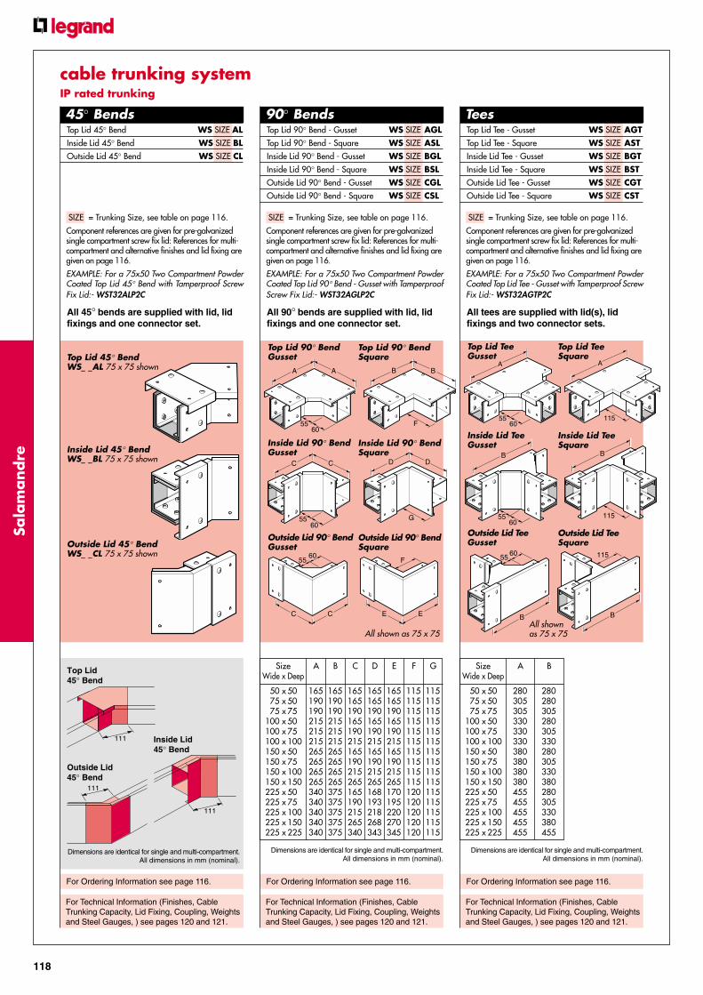
SizeWide x Deep
A
50 x75 x75 x
100 x100 x100 x150 x150 x150 x150 x225 x225 x225 x225 x225 x
280305305330330330380380380380455455455455455
B
280280305280305330280305330380280305330380455
505075507510050751001505075100150225
SizeWide x Deep
A
50 x75 x75 x
100 x100 x100 x150 x150 x150 x150 x225 x225 x225 x225 x225 x
165190190215215215265265265265340340340340340
B
165190190215215215265265265265375375375375375
C
165165190165190215165190215265165190215265340
D
165165190165190215165190215265168193218268343
E
165165190165190215165190215265170195220270345
F
115115115115115115115115115115120120120120120
G
115115115115115115115115115115115115115115115
505075507510050751001505075100150225
115
B
5560
B
115
B
5560
B
115
A
5560
A
E E
F
C C
5560
G
DDCC
5560
B
F
BA
5560
A
For Ordering Information see page 116.
For Technical Information (Finishes, CableTrunking Capacity, Lid Fixing, Coupling, Weightsand Steel Gauges, ) see pages 120 and 121.
Dimensions are identical for single and multi-compartment.All dimensions in mm (nominal).
For Ordering Information see page 116.
For Technical Information (Finishes, CableTrunking Capacity, Lid Fixing, Coupling, Weightsand Steel Gauges, ) see pages 120 and 121.
For Ordering Information see page 116.
Top Lid 90° Bend - Gusset WS SIZE AGLTop Lid 90° Bend - Square WS SIZE ASLInside Lid 90° Bend - Gusset WS SIZE BGLInside Lid 90° Bend - Square WS SIZE BSLOutside Lid 90° Bend - Gusset WS SIZE CGLOutside Lid 90° Bend - Square WS SIZE CSL
Top Lid 45° Bend WS SIZE ALInside Lid 45° Bend WS SIZE BLOutside Lid 45° Bend WS SIZE CL
SIZE = Trunking Size, see table on page 116.
Component references are given for pre-galvanizedsingle compartment screw fix lid: References for multi-compartment and alternative finishes and lid fixing aregiven on page 116.
EXAMPLE: For a 75x50 Two Compartment PowderCoated Top Lid Tee - Gusset with Tamperproof ScrewFix Lid:- WST32AGTP2C
SIZE = Trunking Size, see table on page 116.
Component references are given for pre-galvanizedsingle compartment screw fix lid: References for multi-compartment and alternative finishes and lid fixing aregiven on page 116.
EXAMPLE: For a 75x50 Two Compartment PowderCoated Top Lid 90° Bend - Gusset with TamperproofScrew Fix Lid:- WST32AGLP2C
For Technical Information (Finishes, CableTrunking Capacity, Lid Fixing, Coupling, Weightsand Steel Gauges, ) see pages 120 and 121.
45° Bends 90° Bends Tees
SIZE = Trunking Size, see table on page 116.
Component references are given for pre-galvanizedsingle compartment screw fix lid: References for multi-compartment and alternative finishes and lid fixing aregiven on page 116.
EXAMPLE: For a 75x50 Two Compartment PowderCoated Top Lid 45° Bend with Tamperproof ScrewFix Lid:- WST32ALP2C
All 45° bends are supplied with lid, lidfixings and one connector set.
All 90° bends are supplied with lid, lidfixings and one connector set.
All tees are supplied with lid(s), lidfixings and two connector sets.
Top Lid 45° BendWS_ _AL 75 x 75 shown
Inside Lid 45° BendWS_ _BL 75 x 75 shown
Outside Lid 45° BendWS_ _CL 75 x 75 shown
Top Lid 90° BendGusset
Inside Lid 90° BendGusset
Outside Lid 90° BendGusset
Top Lid Tee - Gusset WS SIZE AGTTop Lid Tee - Square WS SIZE ASTInside Lid Tee - Gusset WS SIZE BGTInside Lid Tee - Square WS SIZE BSTOutside Lid Tee - Gusset WS SIZE CGTOutside Lid Tee - Square WS SIZE CST
Top Lid 90° BendSquare
Inside Lid 90° BendSquare
Outside Lid 90° BendSquare
Top Lid TeeGusset
Inside Lid TeeGusset
Outside Lid TeeGusset
Top Lid TeeSquare
Inside Lid TeeSquare
Outside Lid TeeSquare
Dimensions are identical for single and multi-compartment.All dimensions in mm (nominal).
cable trunking systemIP rated trunking
All shown as 75 x 75All shownas 75 x 75
Dimensions are identical for single and multi-compartment.All dimensions in mm (nominal).
111
Top Lid45° Bend
Inside Lid45° Bend
Outside Lid45° Bend
111
111

119
cable
tru
nk
ing s
yst
emREDUCER SIZE CODESMain run size
in mmWide x Deep
SIZECODE1 2
75 x75 x
100 x100 x100 x150 x150 x150 x150 x
507550751005075100150
32SIZE33SIZE42SIZE43SIZE44SIZE62SIZE63SIZE64SIZE66SIZE
Main run sizein mm
Wide x Deep
SIZECODE1 2
225 x225 x225 x225 x225 x
5075100150225
92SIZE93SIZE94SIZE96SIZE99SIZE
SizeWide x Deep
A
50 x75 x75 x
100 x100 x100 x150 x150 x150 x150 x225 x225 x225 x225 x225 x
280305305330330330380380380380455455455455455
505075507510050751001505075100150225
Connector Set WS SIZE CStop End WS SIZE E
SIZE = Trunking Size, see table on page 116.
Component references are given for pre-galvanizedscrew fix lid: References for alternative finishes and lidfixing are given on page 116.
EXAMPLE: For a 75x50 Powder Coated ConnectorSet with Tamperproof Screw Fix Lid:- WST32CP
EXAMPLE: For a 75x50 Powder Coated Stop Endwith Tamperproof Screw Fix Lid:- WST32EPAll connector sets are supplied withConnector, lid, lid fixings, clamps andconnector to trunking fastenings.
All stop ends are supplied with lids, lidfixings, clamps and connector totrunking fastenings.
For Technical Information (Finishes, CableTrunking Capacity, Lid Fixing, Coupling, Weightsand Steel Gauges, ) see pages 120 and 121.
For Ordering Information see page 116.
For Technical Information (Finishes, CableTrunking Capacity, Lid Fixing, Coupling, Weightsand Steel Gauges, ) see pages 120 and 121.
For Technical Information (Finishes, CableTrunking Capacity, Lid Fixing, Coupling, Weightsand Steel Gauges, ) see pages 120 and 121.
For Ordering Information see page 116.
SIZE = Trunking Size, see table on page 116.
Component reference is given for pre-galvanizedsingle compartment screw fix lid: References for multi-compartment and alternative finishes and lid fixing aregiven on page 116.
EXAMPLE: For a 75x50 Two Compartment PowderCoated Crossover with Tamperproof Screw Fix Lid:-WST32AGXP2C
Reducer SIZES are obtained by giving themain run trunking SIZE (1) followed by thereduced run trunking SIZE (2).
EXAMPLE:For a Reducer, with Screw Fix Lid, reducing from150x150 to 75x75:- WS6633R
For further Ordering Information see page 116.
Crossovers Reducer Connector Set andStop End
Crossover WS SIZE AGX
SIZES = Trunking Sizes, see table below.
Component reference is given for pre-galvanizedscrew fix lid: References for alternative finishes and lidfixing are given on page 116.
EXAMPLE: For a Powder Coated Reducer withTamperproof Screw Fix Lid, reducing from 150x150to 75x75:- WST6633RP
Reducer WS SIZES R
All crossovers are supplied with lid, lidfixings and three connector sets.
All reducers are supplied with lid, lidfixings, one connector set (for reducedrun) and fastenings.
CrossoverWS_ _AGX 75 x 75 shown
ReducerWS_ _ _ _R150 x 100 to 75 x 75 shown
Connector SetWS_ _C75 x 75 shown
Stop EndWS_ _E75 x 75 shown
80
80
40
Connector Set
Stop End
All dimensions in mm (nominal).
cable trunking systemIP rated trunking
A
5560
Dimensions are identical for single and multi-compartment.All dimensions in mm (nominal).

120
Sala
mandre
25 50 deep
Up to 150mm wide
25
19
50 deep
225 and 300mm wide
75100150225300
3863
11472
110
TrunkingDepth B
12.5 16
5075 deep B 75 to
150 deep
12.5 16
40
B
100150
51101
TrunkingDepth A
225 and300 deepB
16
25A 100 and
150 deep
12.5
Straight Length to Fitting JointAll fittings have integral connectors and 7mmknockouts (A) for earth link if required. Ifspecified, an earth link can be provided; an M5or M6 screw can be used for fixing the earthlink.
Drill a 14.1mm hole in lidto accept turnbuckle.
Press turnbuckle into lidand installation iscomplete.
Simply turn 90°clockwise to lock (or anti-clockwise to release),using a No.2 cross headscrewdriver.
Screw FixingScrews are M5 x 6mm (M5 x 10mm for IP RatedTrunking) posidrive, pan head with earth nib onunderside of head and a rounded end to preventcable damage.
Manufactured to BS4183 and BS3643 from lowcarbon mild steel, zinc plated and clear passivated.
Tamperproof Screw FixingAn M5 x 12mm pan head screw with the efficienthigh torque TORX® recess.
Tamperproof screw fix lids are supplied fitted withmild steel plated screws with TORX® screwsbagged separately for fitting when installation iscomplete.
• Torque transmitted positively and accurately.
• Large contact area - reduces wear.
• Parallel sides - holds driver captive andvirtually eliminates slippage and camout.
Manufactured to BS4183 and BS3643 from lowcarbon mild steel, zinc plated and clear passivated.
A special TORX® screwdriver is needed.
Large contactarea, no stressconcentrationsor stress raisers
Drive surfacesparallel with axisof screw reducesdisengagement risk
Coupling DetailsLid Fixing DetailsFinishesTurnbucklesA steel fixing encased within a smooth plastic/die cast moulding, with excellent earth bondingproperties.
Quick, safe, easy to install and time saving.
Plastic Case Steel TurnbuckleFor interior use in non-corrosive and non-aggresive chemical environments.
Die Cast TurnbuckleFor use in aggresive chemical environments andwhere plastic is not suitable.Manufactured from zinc alloy ZL3 and die cast.
Standard Cable TrunkingStandard Finish:
Pre-galvanized steel to BS EN 10142 & 3.Alternative Finish:
Powder Coated (epoxy/polyester) grey toBS4800 00A05.Other RAL colours available.
Stainless Steel Cable TrunkingStandard Finish:
Stainless Steel to BS EN 10088 grade1-4401 (equivalent to 304) mill finish.
Alternative Finishes:Marine grade 316 available on request.Brushed and polished available on request.
IP Rated Cable TrunkingStandard Finish:
Pre-galvanized steel to BS EN 10142 & 3.Additional Finishes:
Powder Coated (epoxy/polyester) grey toBS4800 00A05.Other RAL colours available.Stainless Steel to BS EN 10088 grade1-4401 (equivalent to 304).Marine grade 316 available on request.Brushed and polished available on request.
Fitting additional plastic caseturnbuckles if required
Cable Sizesand Factors
Cable Trunking CapacityFor each size of cable multiply the number to beinstalled by its own common factor. Add togetherthe results of these calculations for all cable sizes.The correct trunking size must have a factor equalto or greater than this total.
Example:24 x 16.0mm2 stranded @50 = 120020 x 2.5mm2 solid @ 10.2 = 204
1404
∴ Trunking size = 75x50 (capacity factor 1555)
Size mm2 (nom.) Factor
SOLID 1.5 7.12.5 10.2
STRANDED 1.5 8.12.5 11.44.0 15.06.0 22.0
10.0 38.016.0 50.025.0 75.035.0 95.050.0 133.070.0 177.095.0 227.0
120.0 284.0150.0 346.0240.0 552.0
Trunking Sizesand CapacityFactors
Size mm Factor
50x50 103775x50 155575x75 2371100x50 2091100x75 3189100x100 4252150x50 3091150x75 4742150x100 6394150x150 9697225x50 4646225x75 7114225x100 9298225x150 14652225x225 21766300x50 6182300x75 9486300x100 12788300x150 19447300x225 28900300x300 38000
This table is based on atheoretical calculationand must be taken onlyas a guide, due regardmust be taken of futurewiring needs.
All dimensions in mm (nominal).
115
5075
100150225300
184368
118193268
17.5018.0018.0017.7518.2518.75
35
AB
Ø 14.1mm holes
150
B
A
PLASTIC CASE TURNBUCKLE
Ø 9.5mm holesDIE-CAST CASE TURNBUCKLE
SCREW FIXED
75 to 150 wide
150
B
A
225 and 300 wide
50mm wide
75 to 150 wide
50 to 300 wide
225 and 300 wide
50mm wide
TrunkingWidth A B
B
150150
B
A
150
B
A
Ø 7.2mm holes must be drilled at the cut end for M5 screws.
5075
100150225300
—45.570.5
120.5195.5270.5
26.516.716.716.517.017.5
TrunkingWidth A B
5075
100150225300
406590
140215290
6.507.257.257.505.005.00
TrunkingWidth A B
150
B
A
Hole Positions for LidsCut to Length
A
Cut LengthsDrill clearance holes in cut length for M5 panhead screws in positions shown below.
All dimensionsin mm (nominal).
cable trunking systemtechnical information

121
cable
tru
nk
ing s
yst
em
The weights given are for Pre-Galvanized finishonly, in kilograms (nominal) and subject to materialthickness tolerance.
Standard Cable Trunking Weights
Trunking Length per metre including lid and connectors1.9 2.8 3.2 3.2 3.7 4.2 4.2 4.7 5.1 7.6 5.6 6.1 7.9 9.2 11.0 7.0 9.0 9.6 10.8 12.6 14.4
Bend0.3 0.4 0.5 0.5 0.6 0.7 0.9 0.9 1.1 1.3 1.6 1.7 2.0 2.4 3.0 2.5 2.7 3.0 3.5 3.7 3.9
Tee0.3 0.4 0.5 0.6 0.7 0.7 0.9 1.0 1.1 1.3 1.6 1.7 1.9 2.2 2.7 2.5 2.6 2.9 3.2 3.4 3.6
Crossover0.4 0.5 0.6 0.6 0.7 0.8 1.0 1.0 1.1 1.3 1.6 1.7 1.8 1.9 2.4 2.5 2.6 2.6 2.8 3.1 3.3
Reducer– 0.5 0.5 0.5 0.7 0.8 0.8 0.9 1.0 1.1 1.3 1.4 1.5 1.6 1.9 1.6 1.7 1.8 1.9 2.2 2.8
Bellmouth0.5 0.8 0.8 1.2 1.3 1.4 1.6 1.7 1.8 1.9 2.1 2.2 2.3 2.4 2.9 2.6 2.7 2.8 2.9 3.4 3.9
Change Face0.6 0.8 1.0 1.0 1.1 1.3 1.3 1.4 1.5 2.3 1.7 1.8 2.4 2.8 3.3 2.1 2.7 2.9 3.2 3.7 4.3
Loose Separator per metre0.4 0.4 0.5 0.4 0.5 0.7 0.4 0.5 0.7 1.0 0.4 0.5 0.7 1.0 1.5 0.4 0.5 0.7 1.0 1.5 2.0
50
x 5
0
75
x 5
0
75
x 7
5
10
0 x
50
10
0 x
75
10
0 x
10
0
15
0 x
50
15
0 x
75
15
0 x
10
0
15
0 x
15
0
22
5 x
50
22
5 x
75
22
5 x
10
0
22
5 x
15
0
22
5 x
22
5
30
0 x
50
30
0 x
75
30
0 x
10
0
30
0 x
15
0
30
0 x
22
5
30
0 x
30
0
weight in kg
Fitting Two ThreeCompartment Compartment
Factor Factor
Bend 1.25 1.50Tee 1.50 2.00Crossover 1.50 2.00Bellmouth 1.25 1.50
Multi Compartment Weights
Trunking LengthsTo calculate the weight of multi-compartmenttrunking add the weight of the relevant number ofloose separators to that of the trunking.
FittingsMultiply the weight of the fitting by the appropriatefactor (see table alongside).
50
x 5
0
75
x 5
0
75
x 7
5
10
0 x
50
10
0 x
75
10
0 x
10
0
15
0 x
50
15
0 x
75
15
0 x
10
0
15
0 x
15
0
22
5 x
50
22
5 x
75
22
5 x
10
0
22
5 x
15
0
22
5 x
22
5
30
0 x
50
30
0 x
75
30
0 x
10
0
30
0 x
15
0
30
0 x
22
5
30
0 x
30
0
Thickness in mm
Steel GaugesAll trunking gauges are to BS4678 and are forPre-Galvanized finish only.
TrunkingLengths 1.0 1.2 1.2 1.2 1.2 1.2 1.2 1.2 1.2 1.4 1.6 1.6 1.6 1.6 1.6 1.6 1.6 1.6 1.6 1.6 1.6*TrunkingLids 1.0 1.2 1.2 1.2 1.2 1.2 1.2 1.2 1.2 1.2 1.6 1.6 1.4 1.4 1.4 1.6 1.6 1.6 1.6 1.6 1.6*
* For full compliance with BS requirements 300x300 trunking isalso available in 2.0mm thickness in lengths of 2.0m.
cable trunking systemtechnical information

LIGHTING TRUNKING
Sala
mandre
LET US LIGHTENYOURWORKLOAD
122
This high quality range of
galvanised steel lighting
trunking offers a diverse
selection of sizes, all of which
can be installed quickly and
with the minimum amount
of hassle.

lighting t
runk
ing s
yst
em
123
www.legrand.co.uk
LIGHTING TRUNKING
The range issupported by a
complete selectionof labour-saving
fittings thatguarantees the
perfect solutionevery time
An easy-fit couplingsystem is suppliedas standard on all
fittings... savingboth time and money
as there is no needfor any additionaldrilling or screw
fixings

124
Sala
mandre
For Trunking Deflection and Weights, see page 129.
Trunking Body
Standard 1.2mm gaugeNominal Steel Thickness
50 x 50 3 metre LT1/312
50 x 50 4 metre LT1/412
50 x 50 5 metre LT1/512
50 x 50 6 metre LT1/612
50 x 25 5 metre LT5/512
Light 1.0mm gaugeNominal Steel Thickness
50 x 50 3 metre LT1/310
50 x 50 4 metre LT1/410
50 x 50 5 metre LT1/510
50 x 50 6 metre LT1/610
Available in two standard sections:50x50mm and 50x25mm.
1.2mm and 1.0mm gauges areavailable.
A choice of 'Clip-in' lids in metal orwhite plastic.
Comprehensive range of fittings andsupport ancillaries.
ORDERING INFORMATION
The information below applies throughout theLighting Trunking range, unless otherwise stated.
The trunking body, coupler and lid are purchasedseparately.
Component ReferencesTrunking Body References are obtained bygiving the type, followed by the size, length andgauge (see table below).
EXAMPLE 1:For 50x50 Pre-galvanized Trunking Body, 4 metrelong, 1.0mm gauge:- LT1/410
For white plastic coated finish add prefix W to thereference.
Lighting Fitting References are obtained bygiving the type, followed by the size and fitting code.
EXAMPLE 2:For 50x25 White Inside Lid 90° Bend:- WLT5BSL
Straight Length toFitting JointTighten the M5 screws(pressing the fitting againstthe top flange of the trunkingbody) to secure.
Trunking Body50x50LT1_
Trunking Body50x25LT5_
LT5
50
25
LT1
50
50
Standard 1.2mm gaugeUse for larger spans when minimum deflectionis required.
Ideal for suspending light fittings or where thetrunking is visible.
Light 1.0mm gaugeUse for shorter spans or where the trunking isconcealed e.g. a cavity ceiling.
A 'Clip-in' lid trunking system for fast installation.
FINISHESStandard Finish:Pre-galvanized steel to BS EN 10142 & 3.
Additional Finish:Powder Coated (epoxy/polyester) white
Type Size Length Gauge
Whi
te
Ligh
ting
50 x
25
50 x
50
3m 4m 5m 6m 1.0m
m
1.2m
m
W LT 51 3 4 5 6 10 12
White 1.2mm gaugeNominal Steel Thickness
50 x 50 5 metre WLT1/512
50 x 25 5 metre WLT5/512
lighting trunking systemtrunking body

125
lighting t
runk
ing s
yst
em
For Straight Length to Fitting joint, see page 124.
Finishes, see page 124. Finishes, see page 124.
For Trunking Deflection and Weights, see page 129. For Trunking Deflection and Weights, see page 129.
For Ordering Information, see page 124. For Ordering Information, see page 124.
Straight Length toLong Coupler JointTighten the M5 screws (pressing thecoupler against the top flange ofthe trunking body) to secure.
Trunking LidsLids simply clip intothe trunking.
They can be cut toany angle to suitfitting, see alongside.
Long CouplerTighten the M5 screws(pressing the coupleragainst the top flange ofthe trunking body) tosecure.
Top Lid 45° Bend50 x 50 LT1AL50 x 25 LT5AL
White 50 x 50 WLT1ALWhite 50 x 25 WLT5AL
Inside Lid 45° Bend50 x 50 LT1BL50 x 25 LT5BL
White 50 x 50 WLT1BLWhite 50 x 25 WLT5BL
Outside Lid 45° Bend50 x 50 LT1CL50 x 25 LT5CL
White 50 x 50 WLT1CLWhite 50 x 25 WLT5CL
45° Bends
Top Lid 45° Bend_AL 50 x 50 shown
Outside Lid 45° Bend_CL 50 x 50 shown
Inside Lid 45° Bend_BL 50 x 50 shown
Lids and Long Coupler
Long Coupler
50 x 50 LT1C
50 x 25 LT5C
Lid - WhiteOverlappingLTPO
Lid - WhiteStandardLTPC
Lid -GalvanizedStandardLTGC
Long CouplerLT_C
250
Lid - Galvanized 2m long
Standard 50mm width LTGC
Lid - White Plastic 2m long
Standard 50mm width LTPC
Overlapping 50mm width LTPO
Fixing lids at a Top Lid 45° Bend junctionCut both lids at 22.5°, then fit into the trunkingand slide into position.
lighting trunking systemtrunking fittings

126
Sala
mandre
Fourway Cover, see page 127.Top Lid 90° Bend Cover, see page 127.
For Straight Length to Fitting joint, see page 124.
Finishes, see page 124.
For Trunking Deflection and Weights, see page 129.
For Ordering Information, see page 124.
For Straight Length to Fitting joint, see page 124.
Finishes, see page 124.
For Trunking Deflection and Weights, see page 129.
For Ordering Information, see page 124.
Top Lid 90° Bend50 x 50 LT1ASL50 x 25 LT5ASL
White 50 x 50 WLT1ASLWhite 50 x 25 WLT5ASL
Inside Lid 90° Bend50 x 50 LT1BSL50 x 25 LT5BSL
White 50 x 50 WLT1BSLWhite 50 x 25 WLT5BSL
Outside Lid 90° Bend50 x 50 LT1CSL50 x 25 LT5CSL
White 50 x 50 WLT1CSLWhite 50 x 25 WLT5CSL
Fourway90° Bends
Top Lid 90° Bend_ASL 50 x 50 shown
Inside Lid 90° Bend_BSL 50 x 50 shown
Outside Lid 90° Bend_CSL 50 x 50 shown
Fourway_ASX 50 x 50 shown
50 x 50 LT1ASX50 x 25 LT5ASX
White 50 x 50 WLT1ASXWhite 50 x 25 WLT5ASX
Fixing lids at a Top Lid 90° Bend junction
Attach fitting cover, see page 127, then fit lids intotrunking and slide under fitting cover.
Overlapping lids will fit flush with the fitting cover.
Fixing lids at a Fourway junctions
Attach fitting cover, see page 127, then fit lids intotrunking and slide under fitting cover.
Overlapping lids will fit flush with the fitting cover.
lighting trunking systemtrunking fittings

127
lighting t
runk
ing s
yst
em
Top Lid 90° Bend Cover50mm wide LT1ASL/LID50mm wide, White WLT1ASL/LID
Top Lid Tee Cover50mm wide LT1AST/LID50mm wide, White WLT1AST/LID
Fourway Cover50mm wide LT1ASX/LID50mm wide, White WLT1ASX/LID
Top Lid Tee Cover, see alongside.
Finishes, see page 124.
For Trunking Deflection and Weights, see page 129.
For Ordering Information, see page 124.
For Straight Length to Fitting joint, see page 124.
Finishes, see page 124.
For Trunking Deflection and Weights, see page 129.
For Ordering Information, see page 124.
Tees
Outside Lid Tee_CST 50 x 50 shown
Top Lid Tee_AST 50 x 50 shown
Inside Lid Tee_BST 50 x 50 shown
Covers for Fittings
Outside Lid Tee50 x 50 LT1CST50 x 25 LT5CST
White 50 x 50 WLT1CSTWhite 50 x 25 WLT5CST
Top Lid Tee50 x 50 LT1AST50 x 25 LT5AST
White 50 x 50 WLT1ASTWhite 50 x 25 WLT5AST
Inside Lid Tee50 x 50 LT1BST50 x 25 LT5BST
White 50 x 50 WLT1BSTWhite 50 x 25 WLT5BST
Top Lid Tee CoverLT1AST/LID
Fourway CoverLT1ASX/LID
The Fitting Cover will simply 'click' into place afterthe fitting to trunking joint has been made.
Fixing lids at a Top Lid Tee junctions
Attach fitting cover, see alongside, then fit lids intotrunking and slide under fitting cover.
Overlapping lids will fit flush with the fitting cover.
Top Lid 90° Bend CoverLT1ASL/LID
lighting trunking systemtrunking fittings
128
Sala
mandre
For Ordering Information, see page 124.
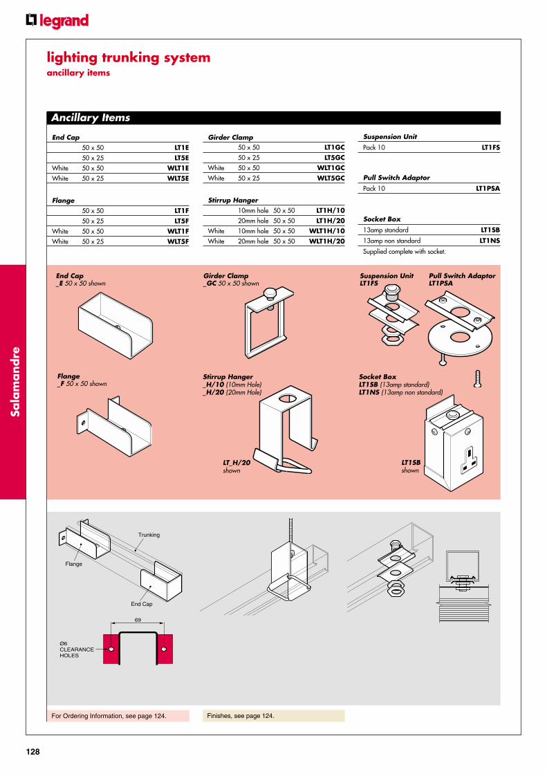
Ancillary Items
Suspension UnitLT1FS
Pull Switch AdaptorLT1PSA
Socket BoxLT1SB (13amp standard)LT1NS (13amp non standard)
LT1SBshown
Stirrup Hanger_H/10 (10mm Hole)_H/20 (20mm Hole)
LT_H/20shown
Girder Clamp_GC 50 x 50 shown
End Cap_E 50 x 50 shown
Flange_F 50 x 50 shown
End Cap50 x 50 LT1E50 x 25 LT5E
White 50 x 50 WLT1EWhite 50 x 25 WLT5E
Flange50 x 50 LT1F50 x 25 LT5F
White 50 x 50 WLT1FWhite 50 x 25 WLT5F
Girder Clamp50 x 50 LT1GC50 x 25 LT5GC
White 50 x 50 WLT1GCWhite 50 x 25 WLT5GC
Stirrup Hanger10mm hole 50 x 50 LT1H/1020mm hole 50 x 50 LT1H/20
White 10mm hole 50 x 50 WLT1H/10White 20mm hole 50 x 50 WLT1H/20
Suspension Unit
Pack 10 LT1FS
Pull Switch Adaptor
Pack 10 LT1PSA
Socket Box
13amp standard LT1SB
13amp non standard LT1NS
Supplied complete with socket.
Trunking
End Cap
Flange
Finishes, see page 124.
69
Ø6CLEARANCEHOLES
lighting trunking systemancillary items

129
lighting t
runk
ing s
yst
em
Cable RetainerLT1CR
Cable Retainer
Pack 10 LT1CR
Klik Adaptor
Pack 10 LT1KL
Male Screwed Hook
LT1MH
Non-standard 13amp Plug
Single pole CO104
Double pole CO105
Klik AdaptorLT1KL
Male ScrewedHookLT1MH
Non-standard 13amp PlugCO104 (single pole)CO105 (double pole)
Trunking BodyStandard1.2mm gauge per metre 1.5
LidsLTGC per metre 0.7LTPC per metre 0.2
Long CouplerLT1C each 0.4
90° BendsLT1ASL each 0.3LT1BSL each 0.4LT1CSL each 0.4
FourwayLT1ASX each 0.6
TeeLT1AST each 0.5
End CapLT1E each 0.2
FlangeLT1F each 0.2
Lighting Trunking Deflection
The weights given are in kilograms (nominal) andsubject to material thickness tolerance.
Weights
The trunking used in the test was LT1/512 (50 x50,5 metre lengths and 1.2mm thick) joined by longcouplers LT1C. Lids were not fitted.
Note:If tested with lids fitted, deflection measurementswould be slightly reduced.
Load(kgs)
Support
End Span End SpanMid Spans
SupportDeflection measuredat centre of span
3 Metre Span
Girder ClampLT1GC each 0.1
Stirrup HangerLT1H/_ each 0.1
Suspension UnitLT1FS each 0.2
Socket BoxLT1SS each 0.4LT1NS each 0.4
Cable RetainerLT1CR per 100 0.3
The data shown alongside was gathered in tests byLegrand, and is given in good faith, it does not howeverconstitute a warranty nor imply any gaurantee.
The loads were applied as point loads throughsuspension units LT1FS.
An end span will give a deflection of about 1.8x thedeflection of the continuous span, this can be eliminatedby supporting the trunking run close to the end of therun.
Deflection (mm)
Load Mid Span End Span(kgs) 3 metre 3 metre
6 2.1 3.99 2.5 4.6
12 3.6 6.615 4.5 8.1
Note:50 x 25 Lighting TrunkingTrunking should be supported at no greater than 2 metrecentres.Maximum point load = 10kgs.
lighting trunking systemtechnical information
Ancillary Items

DATA TRUNKING
Sala
mandre
THOUGHTFULDESIGN
130
Attention to detail during
the design process means
that Salamandre’s data
trunking encompasses a
number of unique features
and thoughtful touches that
make for quicker, easier fitting
and a more secure, higher
quality finished installation.

data
tru
nk
ing s
yst
em
131
www.legrand.co.uk
DATA TRUNKING
Unique radius bendsgently guide cables
around corners,avoiding the tightangles that could
potentially damagefragile data cables
During installation,cables are held in
place by the screwand bridge piece
which also acts as acover fixing, ensuring
a secure fit on thetrunking body

132
Sala
mandre
FinishGrey enamel.
Trunking Lengths - 3mTrunking Lengths - 3m
50mm wide x 50mm deep,1.2mm nominal thickness HG22
75mm wide x 75mm deep,1.6mm nominal thickness HG33
100mm wide x 100mm deep,1.6mm nominal thickness HG44
150mm wide x 150mm deep,1.8mm nominal thickness HG66
90° Bends90° BendsInside cover (150 x 150 not available) NEN SIZE
Outside cover (150 x 150 not available) NEO SIZE
Top cover (150 x 150 not available) NET SIZE
45° Bends45° Inside Cover Bends
HEN SIZE
45° Outside Cover BendsHEO SIZE
45° Top Cover BendsHET SIZE
SIZE = Trunking Size, see table below.
SIZE = Trunking Size, see table below.
TRUNKING SIZE CODESsize in mm
Wide x DeepSIZE
CODE50 x75 x
100 x150 x
5075100150
22334466
The trunking SIZE code should be includedin the component reference where indicated.
90° Inside CoverBend - NEN33
90° Outside CoverBend - NEO33
90° Top CoverBend - NET33
90° Radius InsideCover Bend - RBNA66
90° Radius BendsInside cover RBN SIZE
Inside cover, 150 x 150 (angular bend) RBNA66
Outside cover RBO SIZE
Outside cover, 150 x 150 (angular bend) RBOA66
Top cover RBT SIZE
Top cover, 150 x 150 (angular bend) RBTA66
150 x 150 only available as angular bend
45° Inside CoverBend - HEN33
45° Outside CoverBend - HEO33
45° Top CoverBend - HET33
90° Radius OutsideCover Bend - RBOA66
data trunking systemtrunking lengths and fittings
90° Radius TopCover Bend - RBT33

133
data
tru
nk
ing s
yst
em
Tees and Four WaysTop Cover Tees
NTT SIZE
Radius TeesRTT SIZE
Four WaysNFT SIZE
Ancillary Items
SIZE = Trunking Size, see table on page 132.
Blank EndsBE SIZE
Flange CouplingsFC SIZE
Sleeve CouplingsSC SIZE
Fitting CouplersCR SIZE
Fire BarriersFB SIZE
Pin Racks Type 1PR1/ SIZE
Reducers75 x 75 reduced to 50 x 50 RC33/22
100 x 100 reduced to 50 x 50 RC44/22
100 x 100 reduced to 75 x 75 RC44/33
150 x 150 reduced to 75 x 75 RC66/33
150 x 150 reduced to 100 x 100 RC66/44
Bridge PiecesFor 50mm trunking BP2
For 75mm trunking BP3
For 100mm trunking BP4
For 150mm trunking BP6 SIZE = Trunking Size, see table on page 132.
Top Cover TeeNTT33
Radius TeeRTT33
Blank EndBE33
Flange CouplingFC33
Sleeve CouplingSC33
Fitting CouplerCR22
Fire BarriersFB33
Pin Rack Type 1PR1/33
ReducerRC44/22
Bridge PieceBP3
Four WayNFT33
data trunking systemfittings and ancillary items