25a63a lighting and small power busbar...
TRANSCRIPT

www.eae.com.tr
25A...63A Lighting and Small Power Busbar TrunkingAkcaburgaz Mahallesi,
119. Sokak, No:10 34510
Esenyurt-Istanbul-TURKEY
Tel: +90 (212) 866 20 00
Fax: +90 (212) 886 24 20
T E
ME 04
IEC 60439-2 sISO9001
14001
QUALI
TY
AN
DEN
VIR
ONMENTAL MANAGEM
EN
TS
YSTEM
S
EA
E h
as
full
rig
ht
to m
ake
an
y re
visi
on
s o
r ch
an
ces
on
th
is c
ata
log
ue w
itho
ut
an
y p
rio
r n
otic
e.
ATA
LT
D. /
A.C
.E./
61
2 4
0 6
6C
ata
loq
ue
06-I
ng
. /
Re
v. 0
4 500 P
cs 19/0
2/2
011

w w w . e a e . c o m . t r

2-3
4
5
6
7
8
9
10
11
12-13
14
15
16
CONTENTS
General Description
Order Code System
Technical Characteristics
KAM
KAM Standard Elements
Tap Off Plugs
KAP
KAP Standard Elements
Tap Off Plugs
Fixing and IP Accessories
Certificate
E Declaration Of Conformitys
Standard Busbars
KAM
Standard Busbars
KAP
C
Product Overview

E KAM/KAPLINE
3000750
0 0 0 0
750 750375 375
L1
L2
L3
N
E L E K T R İ K
2 3
KAM and KAP are busbar trunking systems, for
lighting (KAM) and small Power (KAP), designed and
certified in full compliance with international
standards IEC 60439-1 and 2 and IEC 60529. Both
systems have been tested and certified at the CESI
Institute in accordance with the full type test cycle
stated in the relevant IEC codes.
KAM and KAP Busbar Systems
General Description
General Characteristics
The housing is constructed in pregalvanised sheet
metal which provides a substantial earth path. The
housing gives to the line a very high mechanical
strength, particularly suitable for industrial
application and applications in severe climatic
conditions. The conductors are in electrolytic
copper, tin plated and insulated along their full
length (except at tap off positions) with a self
extinguishing plastic sleeve. 2 and 4 conductor
versions are standard ,with 3 or 5 conductor versions
supplied upon request. Each 3 m standard straight
length is provided with 4 tap off points at 75 cm
distance on one side of the trunking.
Feeder units are available for installing at either end
of the system or as a centre feed unit.
The feeder units are IP55 as standard, and will
accept supply cables up to ø16mm. The feeder units
are supplied in kits including end closure and joint
cover.
Feeder Units
The joint is a fast locking type with a single screw.
The joint contacts are silver plated and highly
oversized in comparison with the nominal current to
bear in total safety possible short term current
peaks. The joint is further reinforced with tightening
springs which ensures the proper contact pressure
between the conductors. The joint provides
continuity of the housing when used as the earth
conductor.
Joint
Tap off plugs are available in ratings from 10A to 32A. The plugs are manufactured in a
self extinguishing material. The contacts for the phase and neutral conductors are
silver plated copper to provide the best conductivity and resistance to corrosion. The
tapping units for the KAM and KAP busbar systems have different plug-in
configurations and are not interchangeable. All plugs are equipped with a separate
earth contact and is the first to make and and the last to break. The plugs have been
tested at CESI Laboratories for 50 connection disconnection duty cycles. The tapping
units when plugged into the system provides both a good contact with the main
conductors and a secure fixing of the plug on the housing.
KAM 10B are single phase plugs, with fixed phase, without fuses, prewired with cable,
cross section 3x1.5 mm² and length 1m. They can be supplied with different length
cable on request.
KAM 16 K and KAP 16 K are single phase plugs with fixed phase, available with or
without fuse holders. A three phase version is also available, and can be used as a
phase selectable unit for single phase operations. They can be wired with cables up to
a maximum of Ø11 mm.
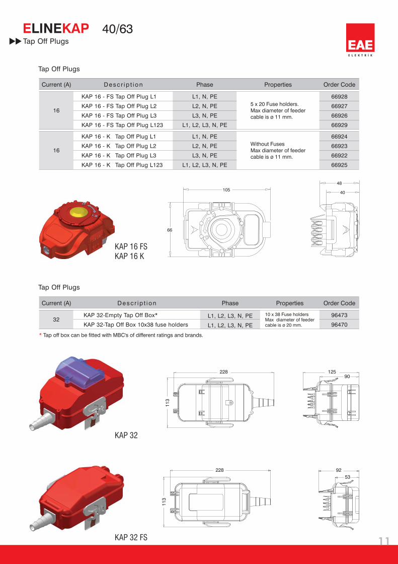
KAP 32 is a three-phase tap off box, available with fuse holder or with DIN rail to accept
standard modular MCB's.
10A Tap Off Plugs (Only for KAM)
16A Tap Off Plugs
Tap Off Plugs
32A Tap Off Box (Only For KAP)

Standard Length
Special Length
Flexible Elbow
Feeder Box
End Feeder Box
Central Feeder Box
002 B --
IP 55 0
KAM T DSS
CodeNumber of
Conductors
2
3
4
5
Conductor Configuration
Configuration
L2, N, PE(Housing)
L2, N, PE+Housing
L1, L2, L3, N, PE(Housing)
L1, L2, L3, N, PE+Housing
2 wire
3 wire
4 wire
5 wire
Busbar Code
KAM
KAP
02
03
04
06
25A
32A
40A
63A
STD
X
FD
BB
BS
BO
4
E L E K T R İ K
E KAM/KAPLINE
5
Busbar Type
Busbar
Rated Current
Busbar
Code
Protection Degree UNPAINTED
PAINTED
-
B
Order Code SystemBUSBAR TYPE
BUSBAR CODE
PROTECTION DEGREE
CONDUCTOR CONFIGURATION
UNPAINTED / PAINTED
COMPONENT
Components
5
V
Hz
kA
kA
kA
m / m
m / m
m / m
W / m
mm
mm
mm
kg/m
kg/m
m / m
m / m
m / m
rms
20
L
R
X
Z
R
X
Z
2
0
0
0
2
2
KAM 02 KAM 03 KAP 04 KAP 06
�
�
�
�
�
�
IEC 439 1-2
690
50/60
IP 55
5
2.27
21
5.31
1.37
5.49
8.58
1.53
8.69
3.23
3.20
18.30
3.20
1.13
1.17
6
2.72
21
4.67
1.11
4.80
7.60
1.22
7.69
4.66
4.00
18.30
4.00
1.17
1.19
7.5
3.4
21
1.70
0.69
1.84
3.48
0.90
3.59
2.68
6.00
18.30
6.00
1.33
1.41
9
4
21
1.45
0.14
1.45
3.22
0.49
3.26
5.68
12.50
18.30
6.00
1.42
1.48
A 25 32 40 63
690 690 690
E L E K T R İ K
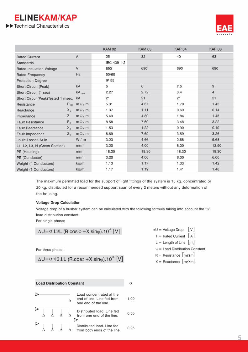
E KAM/KAPLINETechnical Characteristics
Rated Current
Standards
Rated Insulation Voltage
Rated Frequency
Protection Degree
Short-Circuit (Peak)
Short-Circuit (1 sec)
Short Circuit(Peak)Tested 1 msec.
Resistance
Reactance
Impedance
Joule Losses At In
L1, L2, L3, N (Cross Section)
PE (Housing)
PE (Conductor)
Weight (4 Conductors)
Weight (5 Conductors)
Fault Resistance
Fault Reactance
Fault Impedance
Voltage Drop Calculation
U=
U=
I.2L (R.cos
3.I.L (R.cos
V
V
).10
).10
-3
-3
+X.sin�
+X.sin�
The maximum permitted load for the support of light fittings of the system is 15 kg. concentrated or
20 kg. distributed for a recommended support span of every 2 meters without any deformation of
the housing.
For three phase ;
�
�
��
� �
�
����
����
��
��
�
�
U =
I =
L =
=
R =
X = Reactance
m
m
m
m
�
�
�
�
V
A
mt
1.00
0.50
0.25
�
�
Voltage drop of a busbar system can be calculated with the following formula taking into account the “ ”
load distribution constant.
For single phase;
�
Load Distribution Constant
Load concentrated at the
end of line. Line fed from
one end of the line.
Distributed load. Line fed
from one end of the line.
Distributed load. Line fed
from both ends of the line.
Voltage Drop
Rated Current
Length of Line
Load Distribution Constant
Resistance
E KAMLINE 25/32
N
L3
L2
L1
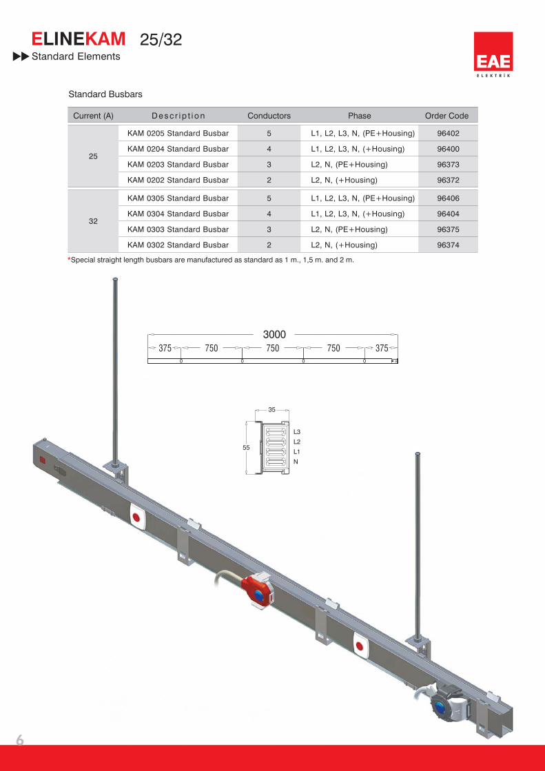
35
55
96402
96400
96373
96372
96406
96404
96375
96374
5
4
3
2
5
4
3
2
25
32
3000
750
0 0 0 0
750 750375 375
E L E K T R İ K
6
Standard Elements
Standard Busbars
Phase Order CodeConductorsCurrent (A) Des c r i p t i on
L1, L2, L3, N, (PE+ )
L1, L2, L3, N, (+ )
L2, N, (PE+ )
L2, N, (+ )
Housing
Housing
Housing
Housing
L1, L2, L3, N, (PE+ )
L1, L2, L3, N, (+ )
L2, N, (PE+ )
L2, N, (+ )
Housing
Housing
Housing
Housing
KAM 0205 Standard Busbar
Standard Busbar
Standard Busbar
Standard Busbar
KAM 0204
KAM 0203
KAM 0202
KAM 0305
KAM 0304
KAM 0303
KAM 0302
Standard Busbar
Standard Busbar
Standard Busbar
Standard Busbar
*Special straight length busbars are manufactured as standard as 1 m., 1,5 m. and 2 m.
E KAMLINE 25/32
75
10
8
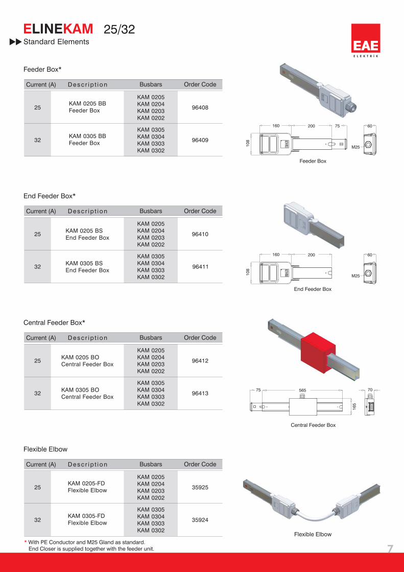
200 60160
M25
10
8
200 75 60
M25
160
35924
35925
96413
96412
96411
96410
96409
96408
KAM 0205
KAM 0204
KAM 0203
KAM 0202
KAM 0205
KAM 0204
KAM 0203
KAM 0202
KAM 0205
KAM 0204
KAM 0203
KAM 0202
KAM 0205
KAM 0204
KAM 0203
KAM 0202
KAM 0305
KAM 0304
KAM 0303
KAM 0302
KAM 0305
KAM 0304
KAM 0303
KAM 0302
KAM 0305
KAM 0304
KAM 0303
KAM 0302
KAM 0305
KAM 0304
KAM 0303
KAM 0302
32
32
32
32
25
25
25
25
E L E K T R İ K
7
565
16
5
70
Feeder Box*
Busbars Order Code
KAM 0305 BB
Feeder Box
KAM 0205 BB
Feeder Box
Current (A) Des c r i p t i on
Standard Elements
Feeder Box
End Feeder Box*
KAM 0305 BS
End Feeder Box
KAM 0205 BS
End Feeder Box
Busbars Order CodeCurrent (A) Des c r i p t i on
End Feeder Box
Central Feeder Box*
KAM 0305 BO
Central Feeder Box
KAM 0205 BO
Central Feeder Box
Busbars Order CodeCurrent (A) Des c r i p t i on
Central Feeder Box
* With PE Conductor and M25 Gland as standard.
End Closer is supplied together with the feeder unit.
Flexible Elbow
KAM 0305-FD
Flexible Elbow
KAM 0205-FD
Flexible Elbow
Busbars Order CodeCurrent (A) Des c r i p t i on
Flexible Elbow

48
40
KAM 16 FS
KAM 16 K
66921
66920
66919
L1, N, PE
L2, N, PE
L3, N, PE
67696
67695
67694
67693
67700
67699
67698
67697
-
-
-
-
-
-
-
L1, N, PE
L2, N, PE
L3, N, PE
L1, L2, L3, N, PE
L1, N, PE
L2, N, PE
L3, N, PE
L1, L2, L3, N, PE
4022
10
16
16
E L E K T R İ K
8
E KAMLINE 25/32
66
105
68
74
KAM 10 B
KAM 16 - FS L1Tap Off Plug
KAM 16 - FS Tap Off Plug L2
KAM 16 - FS Tap Off Plug L3
KAM 16 - FS Tap Off Plug L123
KAM 16 - K L1Tap Off Plug
KAM 16 - K Tap Off Plug L2
KAM 16 - K Tap Off Plug L3
KAM 16 - K Tap Off Plug L123
Tap Off Plugs
Order CodeCurrent (A) Phase PropertiesDesc r ip t i on Cable Length
Tap Off Plugs
Tap Off Plugs
Order Code
* Plugs with different length cable available upon request.
KAM 10 - B L1*Tap Off Plug
KAM 10 - B Tap Off Plug L2*
KAM 10 - B Tap Off Plug L3*
Current (A) Phase PropertiesDesc r ip t i on
1 m. TTR
1 m. TTR
1 m. TTR
Cable
Cable
Cable
Cable Length
With Black Cover
With Yellow Cover
With Blue Cover
Without Fuses.
Max diameter
of feeder cable
is ø11mm.
With 5x20 fuse
holders. Max
diameter of feeder
cable is ø11mm.
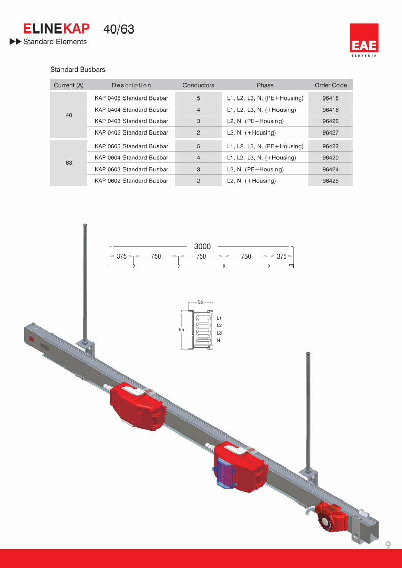
96422
96420
96424
96425
96418
96416
96426
96427
5
4
3
2
5
4
3
2
40
63
N
L1
L2
L3
35
55
3000
750
0 0 0 0
750 750375 375
E L E K T R İ K
9
E KAPLINE 40/63
Standard Busbars
Current (A) Conductors PhaseDesc r ip t i on
L1, L2, L3, N, (PE+ )
L1, L2, L3, N, (+ )
L2, N, (PE+ )
L2, N, (+ )
Housing
Housing
Housing
Housing
L1, L2, L3, N, (PE+ )
L1, L2, L3, N, (+ )
L2, N, (PE+ )
L2, N, (+ )
Housing
Housing
Housing
Housing
KAP 0605
KAP 0604
KAP 0603
KAP 0602
Standard Busbar
Standard Busbar
Standard Busbar
Standard Busbar
KAP 0405 Standard Busbar
KAP 0404
KAP 0403
KAP 0402
Standard Busbar
Standard Busbar
Standard Busbar
Order Code
Standard Elements

10
8
200 60160
M32
10
8
200 75 60
M32
160
63
63
63
63
40
40
40
40
96443
96441
KAP 0405
KAP 0404
KAP 0403
KAP 0402
KAP 0405
KAP 0404
KAP 0403
KAP 0402
KAP 0405
KAP 0404
KAP 0403
KAP 0402
KAP 0405
KAP 0404
KAP 0403
KAP 0402
KAP 0605
KAP 0604
KAP 0603
KAP 0602
KAP 0605
KAP 0604
KAP 0603
KAP 0602
KAP 0605
KAP 0604
KAP 0603
KAP 0602
KAP 0605
KAP 0604
KAP 0603
KAP 0602
96447
96444
95881
35922
95878
35923
75
E L E K T R İ K
10
E KAPLINE 40/63
565
16
5
70
KAP 0605 BB
Feeder Box
KAP 0405 BB
Feeder Box
Feeder Box*
Feeder Box
Busbars Order CodeCurrent (A) Des c r i p t i on
Standard Elements
KAP 0605 BS
End Feeder Box
KAP 0405 BS
End Feeder Box
End Feeder Box*
End Feeder Box
Busbars Order CodeCurrent (A) Des c r i p t i on
KAP 0605 BO
Central Feeder Box
KAP 0405 BO
Central Feeder Box
Central Feeder Box*
Central Feeder Box
Busbars Order CodeCurrent (A) Des c r i p t i on
* With PE Conductor and Special EAE Gland M32 as standard.
KAP 0605-FD
Flexible Elbow
KAP 0405-FD
Flexible Elbow
Flexible Elbow
Busbars Order CodeCurrent (A) Des c r i p t i on
Flexible Elbow
228
11
3
228
11
3
KAP 32
KAP 32 FS
66928
66927
66926
66929
66924
66923
66922
66925
96473
96470
L1, N, PE
L2, N, PE
L3, N, PE
L1, L2, L3, N, PE
L1, N, PE
L2, N, PE
L3, N, PE
L1, L2, L3, N, PE
L1, L2, L3, N, PE
L1, L2, L3, N, PE
12590
92
53
16
16
32
E L E K T R İ K
11
E KAPLINE 40/63
48
40
66
105
KAP 16 FS
KAP 16 K
Tap Off Plugs
Tap Off Plugs
Tap Off Plugs
KAP 16 - FS L1Tap Off Plug
KAP 16 - FS Tap Off Plug L2
KAP 16 - FS Tap Off Plug L3
KAP 16 - FS Tap Off Plug L123
KAP 16 - K L1Tap Off Plug
KAP 16 - K Tap Off Plug L2
KAP 16 - K Tap Off Plug L3
KAP 16 - K Tap Off Plug L123
* Tap off box can be fitted with MBC's of different ratings and brands.
Order CodeCurrent (A) Phase PropertiesDesc r ip t i on
KAP 32-Empty Tap Off Box*
holdersKAP 32-Tap Off 10x38 fuseBox
10 x 38 Fuse holdersMax diameter of feedercable is ø 20 mm.
Order CodeCurrent (A) Phase PropertiesDesc r ip t i on
Without Fuses
Max diameter of feeder
cable is ø 11 mm.
5 x 20 Fuse holders.
Max diameter of feeder
cable is ø 11 mm.
Order Code
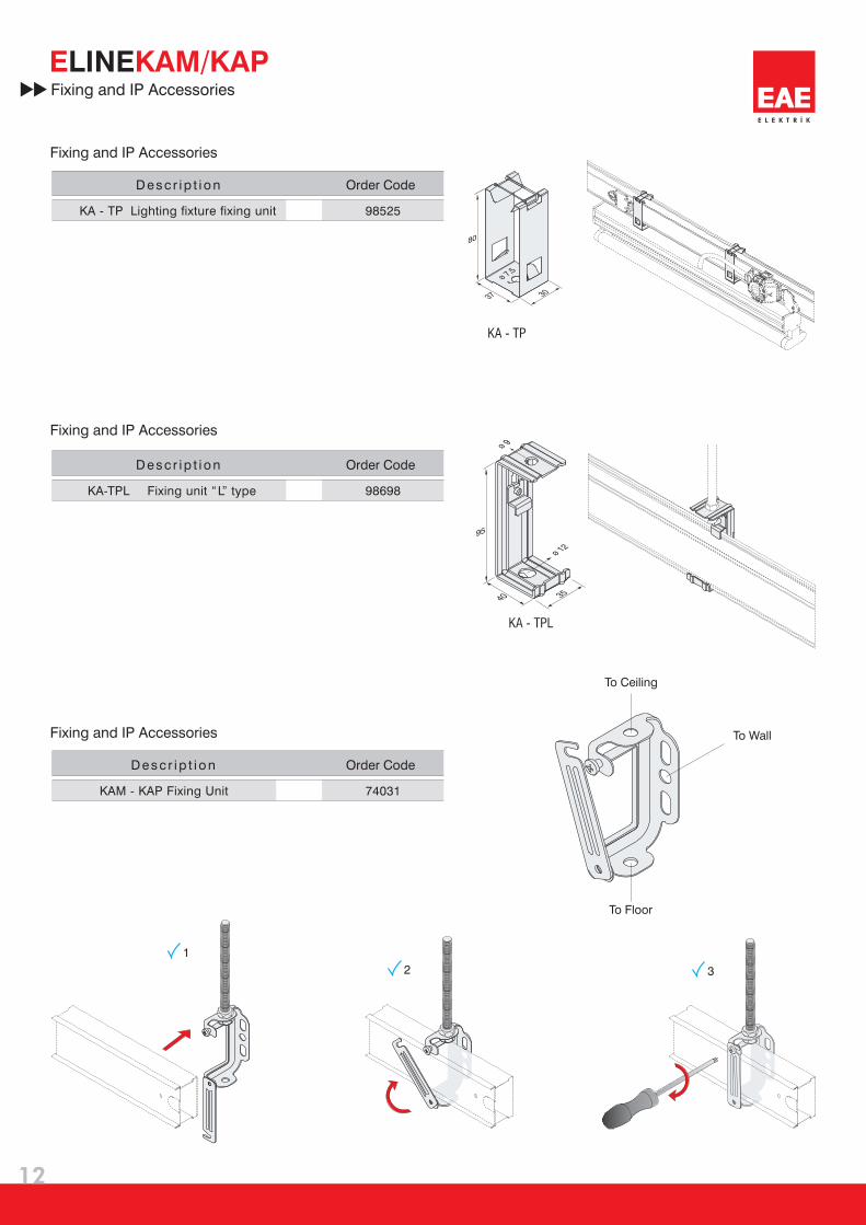
98525KA - TP Lighting fixture fixing unit
Desc r ip t i on
Order Code
98698KA-TPL Fixing unit “L” type
Desc r ip t i on
Order Code
74031
Desc r ip t i on
KA - TP
80
3037
ø 7,5
KA - TPL
95
3540
ø 9
ø 12
1
2 3
E L E K T R İ K
12
E KAM/KAPLINEFixing and IP Accessories
Fixing and IP Accessories
To Ceiling
To Floor
To Wall
KAM - KAP Fixing Unit
Fixing and IP Accessories
Fixing and IP Accessories

96449KA-TD Side Wall Support
98699KA - TPU TPU Fixing unit “U” type
98707KAM-KAP Mechanical Joint Support
56
15
17115
ø 7
ø 8
ø 7
KA - TPU
55
4020
ø 7,5
60
25
20
ø 7,5
E L E K T R İ K
13
E KAM/KAPLINEFixing and IP Accessories
Order CodeDesc r ip t i on
Order CodeDesc r ip t i on
Order CodeDesc r ip t i on
Side Wall Support
Fixing unit “U” type
Joint Support
KA-TD Side Wall Support
Mechanical Joint Support

14
E L E K T R İ K
E KAM/KAPLINECertificates
15
E KAM/KAPLINE
E L E K T R İ K
E L E K T R İ K
EAE Elektrik A.Ş.
Directive
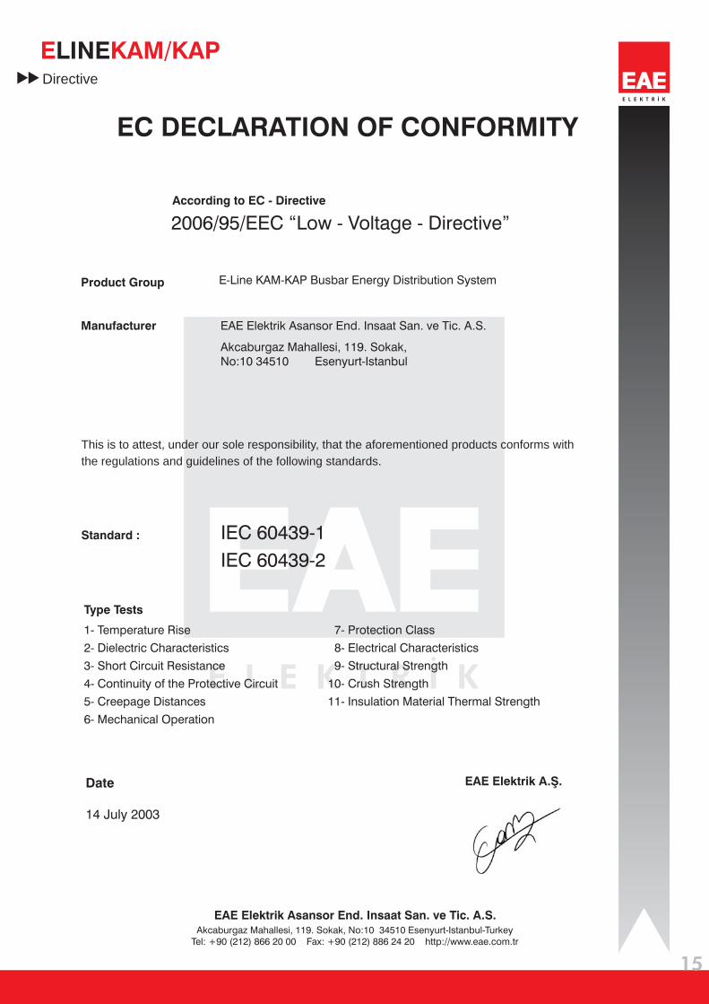
EC DECLARATION OF CONFORMITY
Product Group
Manufacturer
E-Line KAM-KAP Busbar Energy Distribution System
EAE Elektrik Asansor End. Insaat San. ve Tic. A.S.
Akcaburgaz Mahallesi, 119. Sokak,
No:10 34510 Esenyurt-Istanbul
According to EC - Directive
2006/95/EEC “Low - Voltage - Directive”
Standar :d IEC 60439-1
IEC 60439-2
This is to attest, under our sole responsibility, that the aforementioned products conforms with
the regulations and guidelines of the following standards.
Type Tests
1- Temperature Rise
2- Dielectric Characteristics
3- Short Circuit Resistance
4- Continuity of the Protective Circuit
5- Creepage Distances
6- Mechanical Operation
7- Protection Class
8- Electrical Characteristics
9- Structural Strength
10- Crush Strength
11- Insulation Material Thermal Strength
Akcaburgaz Mahallesi, 119. Sokak, No:10 34510 Esenyurt-Istanbul-Turkey
Tel: +90 (212) 866 20 00 Fax: +90 (212) 886 24 20 http://www.eae.com.tr
EAE Elektrik Asansor End. Insaat San. ve Tic. A.S.
Date
14 July 2003

16
E L E K T R İ K
E L E K T R İ K
E KAM/KAPLINE
25A - 63A PLUG-IN BUSBAR SYSTEMS
PRODUCT OVERVIEW
(E-Line KAM / KAP)
1-
2-
3-
4-
5-
6-
7-
8-
9-
10-
11-
12-
13-
The busbar sytem shall have rated current levels between 25A and 63A and
shall have copper conductors.
Plug-in busbar system shall have one of the following conductor number and
configurations;
a) 2 conductors : L1 / N / Housing (Earthing)
b) 3 conductors : L1 / N / PE + Housing (PE conductor and housing are connected)
c) 4 conductors : L1 / L2 / L3 / N / Housing (Earthing)
d) 5 conductors : L1 / L2 / L3 / N / PE + Housing (PE conductor and housing are connected)
Housing shall be used as earth conductor.
The rated insulation voltage of the system shall be 630 V.
On a three meter standard length there shall be four plug-in points.
The conductors in the housing shall be continuously insulated and only peeled off
on the plug-in points to create contact area.
There shall be insulator supports at the plug-in points.
The conductors shall be of electrolytic copper and continuously tin plated.
Each current rating of the busbar system shall have a type test report according to
IEC 60439/2. The type test reports shall be from an internationally accepted third
party laboratory.
Joint of the busbar shall slide into each other; joint contacts shall be silver plated.
To ensure a safe joint contact there shall be springs on both sides of joint
contacts.
IP Protection degree of the busbars shall be 55.
The housing of the busbar shall be manufactured of 0,50 mm thick galvanised
sheet metal.
Contacts of the tap offs shall be off jawed structure, which touches the conductors
on both sides. The contacts shall also have springs.
Manufacturing facility of busbar systems shall have ISO 9001 and ISO 14001 certification.
Product Overview

Compact Busbar Distribution System800...6300A
Plug-in Busbar Distribution System160...800A
Small Power Plug-in Busbar Distribution System100-160-225A
Plug-in Busbar Distribution System40-63A
Multi-Conductor Lighting Busbar System25-32-40A
Lighting Busbar System25-32-40A
Multi Conductor Trolley Busbar System35...250A
Underfloor Ducting Systems
Raised Floor Energy Distribution Systems25...63A
CableTray Systems
E-LINE KB
E-LINE KO
E-LINE MK
E-LINE KAP
E-LINE DL
E-LINE KAM
E-LINE TB
E-LINE DK
E-LINE DKY
E-LINE UK